EP1131547B1 - Saugrohr mit schaltelement - Google Patents
Saugrohr mit schaltelement Download PDFInfo
- Publication number
- EP1131547B1 EP1131547B1 EP99959282A EP99959282A EP1131547B1 EP 1131547 B1 EP1131547 B1 EP 1131547B1 EP 99959282 A EP99959282 A EP 99959282A EP 99959282 A EP99959282 A EP 99959282A EP 1131547 B1 EP1131547 B1 EP 1131547B1
- Authority
- EP
- European Patent Office
- Prior art keywords
- intake manifold
- sealing
- switching element
- sealing ring
- discs
- Prior art date
- Legal status (The legal status is an assumption and is not a legal conclusion. Google has not performed a legal analysis and makes no representation as to the accuracy of the status listed.)
- Expired - Lifetime
Links
- 238000007789 sealing Methods 0.000 claims abstract description 106
- 239000011324 bead Substances 0.000 claims description 8
- 230000000694 effects Effects 0.000 claims description 7
- 239000000565 sealant Substances 0.000 description 18
- 238000009434 installation Methods 0.000 description 16
- 239000004033 plastic Substances 0.000 description 7
- 239000000463 material Substances 0.000 description 4
- 230000008859 change Effects 0.000 description 3
- 238000013461 design Methods 0.000 description 3
- HUWSZNZAROKDRZ-RRLWZMAJSA-N (3r,4r)-3-azaniumyl-5-[[(2s,3r)-1-[(2s)-2,3-dicarboxypyrrolidin-1-yl]-3-methyl-1-oxopentan-2-yl]amino]-5-oxo-4-sulfanylpentane-1-sulfonate Chemical compound OS(=O)(=O)CC[C@@H](N)[C@@H](S)C(=O)N[C@@H]([C@H](C)CC)C(=O)N1CCC(C(O)=O)[C@H]1C(O)=O HUWSZNZAROKDRZ-RRLWZMAJSA-N 0.000 description 2
- 238000005452 bending Methods 0.000 description 2
- 230000008901 benefit Effects 0.000 description 2
- 150000001875 compounds Chemical class 0.000 description 2
- 230000005489 elastic deformation Effects 0.000 description 2
- FYYHWMGAXLPEAU-UHFFFAOYSA-N Magnesium Chemical compound [Mg] FYYHWMGAXLPEAU-UHFFFAOYSA-N 0.000 description 1
- 229910000831 Steel Inorganic materials 0.000 description 1
- 230000009471 action Effects 0.000 description 1
- 239000000853 adhesive Substances 0.000 description 1
- 230000001070 adhesive effect Effects 0.000 description 1
- XAGFODPZIPBFFR-UHFFFAOYSA-N aluminium Chemical compound [Al] XAGFODPZIPBFFR-UHFFFAOYSA-N 0.000 description 1
- 229910052782 aluminium Inorganic materials 0.000 description 1
- 238000013459 approach Methods 0.000 description 1
- 230000015572 biosynthetic process Effects 0.000 description 1
- 238000005266 casting Methods 0.000 description 1
- 238000002485 combustion reaction Methods 0.000 description 1
- 238000010276 construction Methods 0.000 description 1
- 230000007423 decrease Effects 0.000 description 1
- 229920001971 elastomer Polymers 0.000 description 1
- 238000005516 engineering process Methods 0.000 description 1
- 230000002349 favourable effect Effects 0.000 description 1
- 210000003746 feather Anatomy 0.000 description 1
- 229920001821 foam rubber Polymers 0.000 description 1
- 238000009415 formwork Methods 0.000 description 1
- 238000003780 insertion Methods 0.000 description 1
- 230000037431 insertion Effects 0.000 description 1
- 229910052749 magnesium Inorganic materials 0.000 description 1
- 239000011777 magnesium Substances 0.000 description 1
- 238000004519 manufacturing process Methods 0.000 description 1
- 238000000034 method Methods 0.000 description 1
- 238000000465 moulding Methods 0.000 description 1
- 238000012805 post-processing Methods 0.000 description 1
- 238000003825 pressing Methods 0.000 description 1
- 230000008569 process Effects 0.000 description 1
- 230000009467 reduction Effects 0.000 description 1
- 229920002379 silicone rubber Polymers 0.000 description 1
- 239000010959 steel Substances 0.000 description 1
- 210000002105 tongue Anatomy 0.000 description 1
- 238000012549 training Methods 0.000 description 1
Images

Classifications
-
- F—MECHANICAL ENGINEERING; LIGHTING; HEATING; WEAPONS; BLASTING
- F02—COMBUSTION ENGINES; HOT-GAS OR COMBUSTION-PRODUCT ENGINE PLANTS
- F02B—INTERNAL-COMBUSTION PISTON ENGINES; COMBUSTION ENGINES IN GENERAL
- F02B27/00—Use of kinetic or wave energy of charge in induction systems, or of combustion residues in exhaust systems, for improving quantity of charge or for increasing removal of combustion residues
- F02B27/02—Use of kinetic or wave energy of charge in induction systems, or of combustion residues in exhaust systems, for improving quantity of charge or for increasing removal of combustion residues the systems having variable, i.e. adjustable, cross-sectional areas, chambers of variable volume, or like variable means
- F02B27/0226—Use of kinetic or wave energy of charge in induction systems, or of combustion residues in exhaust systems, for improving quantity of charge or for increasing removal of combustion residues the systems having variable, i.e. adjustable, cross-sectional areas, chambers of variable volume, or like variable means characterised by the means generating the charging effect
- F02B27/0247—Plenum chambers; Resonance chambers or resonance pipes
- F02B27/0257—Rotatable plenum chambers
-
- F—MECHANICAL ENGINEERING; LIGHTING; HEATING; WEAPONS; BLASTING
- F02—COMBUSTION ENGINES; HOT-GAS OR COMBUSTION-PRODUCT ENGINE PLANTS
- F02B—INTERNAL-COMBUSTION PISTON ENGINES; COMBUSTION ENGINES IN GENERAL
- F02B27/00—Use of kinetic or wave energy of charge in induction systems, or of combustion residues in exhaust systems, for improving quantity of charge or for increasing removal of combustion residues
- F02B27/02—Use of kinetic or wave energy of charge in induction systems, or of combustion residues in exhaust systems, for improving quantity of charge or for increasing removal of combustion residues the systems having variable, i.e. adjustable, cross-sectional areas, chambers of variable volume, or like variable means
- F02B27/0205—Use of kinetic or wave energy of charge in induction systems, or of combustion residues in exhaust systems, for improving quantity of charge or for increasing removal of combustion residues the systems having variable, i.e. adjustable, cross-sectional areas, chambers of variable volume, or like variable means characterised by the charging effect
- F02B27/0215—Oscillating pipe charging, i.e. variable intake pipe length charging
-
- F—MECHANICAL ENGINEERING; LIGHTING; HEATING; WEAPONS; BLASTING
- F02—COMBUSTION ENGINES; HOT-GAS OR COMBUSTION-PRODUCT ENGINE PLANTS
- F02B—INTERNAL-COMBUSTION PISTON ENGINES; COMBUSTION ENGINES IN GENERAL
- F02B27/00—Use of kinetic or wave energy of charge in induction systems, or of combustion residues in exhaust systems, for improving quantity of charge or for increasing removal of combustion residues
- F02B27/02—Use of kinetic or wave energy of charge in induction systems, or of combustion residues in exhaust systems, for improving quantity of charge or for increasing removal of combustion residues the systems having variable, i.e. adjustable, cross-sectional areas, chambers of variable volume, or like variable means
- F02B27/0226—Use of kinetic or wave energy of charge in induction systems, or of combustion residues in exhaust systems, for improving quantity of charge or for increasing removal of combustion residues the systems having variable, i.e. adjustable, cross-sectional areas, chambers of variable volume, or like variable means characterised by the means generating the charging effect
- F02B27/0247—Plenum chambers; Resonance chambers or resonance pipes
- F02B27/0263—Plenum chambers; Resonance chambers or resonance pipes the plenum chamber and at least one of the intake ducts having a common wall, and the intake ducts wrap partially around the plenum chamber, i.e. snail-type
-
- Y—GENERAL TAGGING OF NEW TECHNOLOGICAL DEVELOPMENTS; GENERAL TAGGING OF CROSS-SECTIONAL TECHNOLOGIES SPANNING OVER SEVERAL SECTIONS OF THE IPC; TECHNICAL SUBJECTS COVERED BY FORMER USPC CROSS-REFERENCE ART COLLECTIONS [XRACs] AND DIGESTS
- Y02—TECHNOLOGIES OR APPLICATIONS FOR MITIGATION OR ADAPTATION AGAINST CLIMATE CHANGE
- Y02T—CLIMATE CHANGE MITIGATION TECHNOLOGIES RELATED TO TRANSPORTATION
- Y02T10/00—Road transport of goods or passengers
- Y02T10/10—Internal combustion engine [ICE] based vehicles
- Y02T10/12—Improving ICE efficiencies
Definitions
- the invention relates to a suction tube with a switching element, in particular for Influencing the length of different pipe sections of the intake manifold after the genus of claim 1.
- Shift suction pipes are well known.
- Switching elements are primarily the lengths of the suction channels, the Air collectors connect with the cylinder inlets, affected. To this end the switching elements must be movable. In most cases these are therefore cylindrical, with a rotation of the switching elements the desired change in length in the intake manifold can be made.
- the switching elements communicate with the walls of the suction pipe.
- the between Saugrohrwandung and switching element resulting column as close as possible be, even if an absolute tightness is not necessary, since this is about Gaskets between clean air ducts goes.
- This can be achieved by a achieve high dimensional accuracy of the switching elements and the Saugrohrwandungen and assist by providing sealing rings.
- the document DE 38 07 193 A1 shows a suction pipe with an inlet, cylinder-side outlet and a switching element which forms a shift drum and movable in the intake manifold is arranged.
- the shift drum is used in particular for influencing the Length of different pipe sections of the intake manifold.
- To seal are between the suction tube and the shift drum sealing rings, which in grooves of the Shift drum are arranged, provided.
- the task is therefore a suction tube with sealants between Switching element and associated mounting hole to create, which is without Assemble problems and thereby to an optimal sealing of the pipe sections the suction tube with each other leads, this seal largely regardless of the occurring on the intake manifold and switching element Tolerances is.
- the intake manifold according to the invention has at least one switching element, which is movably arranged in the suction pipe. Between the walls of the Suction tube and the switching element arise column. These columns are through Sealant sealed, which are supported in the suction tube, so that a relative movement between sealant and switching element during movement of the latter results.
- the sealing means are at least partially elastic and so designed that their installation to an elastic deformation of the elastic parts or the entire sealant leads. This can be used, a contact pressure to produce, either for fixing the sealant in the intake manifold is used or to achieve a sealing effect between the switching element and sealants.
- the fixation of the sealant in the intake manifold may alternatively take place by a positive connection, in particular a groove.
- the positive engagement does not prevent the sealing effect of the sealant, So z. B. allows the contact pressure of the sealant on the switching element. If the sealant pressed on the switching element, so a touch generated between these components, the contact pressure must be chosen so low be that a relative movement between the sealant and switching element is still possible.
- a non-contact seal in particular a labyrinth seal, be provided.
- the fixation of the sealant in the intake manifold may alternatively to the above-mentioned positive and non-positive Connection options also cohesive, especially by an adhesive bond, done.
- the sealants described above are for coarse plastic suction pipes and their switching elements made of plastic suitable.
- the intake manifold according to the invention can also be made of other materials than plastic, z. As aluminum or magnesium or a combination of these materials.
- the Switching element is particularly advantageous for the reasons mentioned a design of the Switching element as a cylindrical body, in particular as a shift drum.
- Out of roundness of the shift drum or the cylindrical mounting hole arise on the circumference different gap dimensions, which are compensated by the sealant can be.
- This is especially by providing grooves in the Switching drum achievable, wherein the sealing means in cooperation with these Grooves yield a labyrinth seal.
- the made for the shift drum Statements also apply to rotary valves.
- the sealing means can according to a further embodiment of the invention but also be designed as a sealing strips.
- the sealing strips leave a seal along the gap formed by Saugrohrwandung and switching element to a degree.
- According to the elasticity of the sealing strip is also an easy wound or curved shape of the sealing gap feasible.
- a seal by sealing strips can z. B. done with sliders. Continue to be on this way possibly sealing gaps on the front sides of cylindrical switching elements sealed.
- the sealing strip in a cylindrical mounting hole parallel to the axis of rotation of a cylindrical switching element to be appropriate.
- cylindrical mounting holes is according to an appropriate training of the inventive idea of the sealing ring to perform annular.
- He can advantageously on the outer circumference have an elastic layer according to the installation rests against the walls of the suction tube and so for a fixation provides.
- the elastic layer is preferably made of silicone or foam rubber.
- To the contact pressure for fixing the sealing ring to the intake manifold to increase the ring can be provided with a larger diameter, as available in the mounting hole. He must then be slotted to to be able to elastically deform it for installation.
- the slot can be carried out in this way be that overlap the ends of the sealing ring around in the slotted Range to achieve optimum sealing effect.
- the slot can also consist of a recess that is wide enough to have a sealing strip in provide the cylindrical mounting hole that crosses the sealing rings.
- the intake manifold housing is split longitudinally, it may be on the slot in the sealing rings be waived.
- the sealing rings can then before assembling the Housing shells are inserted into the mounting hole.
- the sealing rings can e.g. consist of a rigid ring in the outer circumference of a groove is introduced for receiving a sealing ring.
- the sealing ring is the elastic one Location.
- a favorable embodiment of the sealing ring provides, this on the inner circumference to be provided with a hose spring. This is when installing the Sealing ring compressed and thereby exerts an outward Radial force on the sealing ring, which for an additional contact pressure of the Sealing ring to the Saugrohrwandung provides.
- the sealing ring can then be very soft be executed and thereby out of roundness in the cylindrical mounting hole adapt very well.
- This design of the sealing ring is on Best with the above-described, with grooves in the switching element cooperating Labyrinth seal combined.
- the bending softness of the sealing ring can except by a suitable choice of material by a change be influenced of the ring cross-section.
- sealant form-fitting manner in grooves of Saugrohrwandungen stored, and should they themselves to produce the tightness on the Support switching element, it is advantageous to the contact pressure by an elastic To produce element which is located in the grooves in the Saugrohrwandung located and within the meaning of claim 1 as part of the sealant becomes.
- This can be z. B. done by a wave-shaped bending spring.
- Such Arrangement is particularly suitable for sealing strips, but also with Seal can be realized.
- the sealing ring of two discs build. These are at their outer edges with an elastic connection Provided.
- the discs can be made of steel, being used as an elastic connection In particular, a hose is used, with the outer edges the discs is glued.
- the discs can also consist of plastic, wherein the elastic compound consisting of z. B. off Rubber, molded in multi-component technology on the outer edges of the discs is.
- the installation of the sealing rings takes place by insertion into the cylindrical Installation opening. These can in the undeformed state based on the Inner diameter of the mounting hole with undersize or slight oversize be made so that the assembly forces are small.
- a particular embodiment of the disk-shaped sealing rings provides that between the discs a snap connection locks, the fixed the sealing ring in the installed state. This has the advantage that the occurring Friction between the groove flanks described above and the Sealing ring can be minimized. So is a non-contact labyrinth seal between these components possible.
- sealant beads are provided with the switching elements in contact. It is also possible the bulges so on Attach switching element, that they are engaged with the sealing means. Furthermore, such beads can the effect of labyrinth seals as Increase flow obstruction.
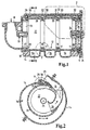
- variable intake manifold shown in Figure 1 is constructed substantially cylindrical, wherein on the one end face an inlet 10 for the filtered intake air and on the other end face a lid 11 having an installation opening for a Shift drum 12 releases, are provided. With the cover removed, the Shift roller 12 are pushed into the interior of the suction tube. This points in the installed state, two bearings 13, with which they are in one Intake manifold housing 14 and in the lid 11 is supported. The cover side bearing has at the same time a receptacle 15 for a drive, not shown Shift drum 12 on.
- the suction tube is intended for the operation of a three-cylinder internal combustion engine.
- Intake passages 16 to the cylinders are formed by parts of the inner wall the suction tube housing 14 and the outer wall of the shift drum 12.
- the suction channels thus extend annularly around the shift drum 12.
- the shift drum 12 consists of a drum 20, which is provided with a closure disc 21 is provided and forms a collector volume in this way. Of the Drum bottom is not closed but consists of spoke-shaped Ribs 23. These ensure that regardless of the angular position of Shift drum 12, the intake air from the inlet 10 into the accumulator volume 22 pass can. Implied screw 24 are used for attachment the closure plate 21 on the drum 20, the lid 11 on the intake manifold 14 and one of the bearings 13 in the closure plate 21st
- the sealing strip is located in a longitudinal groove 29 in the intake manifold 14, which are parallel to the axis of rotation the shift drum 12 extends, and is by a plurality of corrugated springs 30 (see Figure 1) pressed against them shift drum 12.
- the corrugated springs 30 are located in keyways 31, which are separated from each other by separating blocks 32 (see Figure 1).
- FIG. 3 shows the mode of operation of the sealing strip 28. This figure is for explanation and is not a direct subject of the invention.
- the Sealing strip 28 is guided by the longitudinal groove 29 and through in the Fedemut 31 accommodated corrugated springs 30 which are supported in the groove bottom of the longitudinal groove 29, pressed against the shift drum 12. This can be under the sealing strip turn back and forth in the indicated direction of the arrow.
- FIG. 4 shows the mode of action of the sealing ring 17.
- This has an elastic layer 34, which leads to a sealing support of the sealing ring in a cylinder portion 18 of the intake manifold 14 leads.
- a Hose spring 36 housed to the To increase contact pressure of the sealing ring 17 is in an inner ring groove 35 .
- This consists of a coil spring 37, which is fitted together by means of a hose 38 into a ring and is inserted in the inner ring groove 35 in a compressed state. Thereby it reinforces the radially outward pressure of the sealing ring 17.
- On the sealing ring are still on its side edges two Dichtwulste 33 attached. These sealing beads act together with the groove 19 in the shift drum 12 and thereby form a labyrinth seal. in case of an unintentional contact of the sealing beads 33 with the groove flanks, z. By tolerances, the friction is low due to the small bead area.
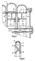
- FIG. 17 An alternative construction of the sealing rings 17 is shown in FIG. These exist of two disks 39, which by an elastic connection 40 on the outer circumference connected to each other.
- the shift drum 12 is at this Design constructed of several discs 41. Sealing rings 17 and Switching disks 41 are changed during installation in the intake manifold housing 14 pushed onto a drive shaft 42. The distance between the Shift discs 41 in the region of the sealing rings 17 by their axial hub length established. The switching discs are on the drive shaft 42 by a Circlip 43 secured against axial slipping. The drive of the drive shaft 42 takes place at the end, not shown.
- the exterior of the indexing disks is connected to the hubs 44 by ribs 23a.
- the interior of the switching disks 41 is used as a collector volume 22. Every second switching disk is radial by means of a feather key connection 47 fixed on the drive shaft 43.
- the switching discs have a bevel gear 45, so that in each case via an unillustrated, fixed housing bevel gear a radially fixed switching disc with the adjacent radial unspecified switching disc communicates in such a way that they are in opposite directions rotate.
- the intake manifold 14 is otherwise described as in Figure 1 built up.
- switching discs 41 and sealing rings 17 are the latter compressed by the switching disks such that between the Disks 39 located, tubular elastic connections 40 against the cylinder sections 18 of the intake manifold 14 are pressed. Thereby These are fixed in the intake manifold, so that when adjusting the Wenntsaugrohres a relative movement between the counter-rotating Shift discs 41 and the sealing rings 17 takes place.
- the sealing ring 17 a at the Last switching disc, which is not inserted between two switching discs, can be designed according to Figure 4.
- FIG. 6 shows an alternative embodiment of a sealing ring 17 according to FIG 5.
- This consists of plastic discs produced by the primary molding process, which are connected by a second elastic component, which is elastic Compound 40 acts.
- the elastic Compound 40 arched outward creating a. Fixation in the intake manifold housing comes about.
- the discs are 39 held together by a snap connection 46.
- the plastic discs each have an annular sealing bead 33, which in the built-in Condition with the not shown switching discs 41 is engaged.
Landscapes
- Engineering & Computer Science (AREA)
- Chemical & Material Sciences (AREA)
- Combustion & Propulsion (AREA)
- Mechanical Engineering (AREA)
- General Engineering & Computer Science (AREA)
- Characterised By The Charging Evacuation (AREA)
- Gasket Seals (AREA)
- Manufacture Of Switches (AREA)
- Electric Vacuum Cleaner (AREA)
- Reciprocating Pumps (AREA)
- Package Closures (AREA)
- Ultra Sonic Daignosis Equipment (AREA)
- Endoscopes (AREA)
- External Artificial Organs (AREA)
- Switches Operated By Changes In Physical Conditions (AREA)
Applications Claiming Priority (3)
| Application Number | Priority Date | Filing Date | Title |
|---|---|---|---|
| DE19853741A DE19853741A1 (de) | 1998-11-21 | 1998-11-21 | Saugrohr mit Schaltelement |
| DE19853741 | 1998-11-21 | ||
| PCT/EP1999/008846 WO2000031391A1 (de) | 1998-11-21 | 1999-11-17 | Saugrohr mit schaltelement |
Publications (2)
| Publication Number | Publication Date |
|---|---|
| EP1131547A1 EP1131547A1 (de) | 2001-09-12 |
| EP1131547B1 true EP1131547B1 (de) | 2004-03-10 |
Family
ID=7888547
Family Applications (1)
| Application Number | Title | Priority Date | Filing Date |
|---|---|---|---|
| EP99959282A Expired - Lifetime EP1131547B1 (de) | 1998-11-21 | 1999-11-17 | Saugrohr mit schaltelement |
Country Status (9)
| Country | Link |
|---|---|
| US (1) | US6550439B1 (enExample) |
| EP (1) | EP1131547B1 (enExample) |
| JP (1) | JP2002530585A (enExample) |
| KR (1) | KR100602749B1 (enExample) |
| AT (1) | ATE261545T1 (enExample) |
| BR (1) | BR9916791A (enExample) |
| CA (1) | CA2352225A1 (enExample) |
| DE (2) | DE19853741A1 (enExample) |
| WO (1) | WO2000031391A1 (enExample) |
Families Citing this family (5)
| Publication number | Priority date | Publication date | Assignee | Title |
|---|---|---|---|---|
| LU90776B1 (en) * | 2001-05-15 | 2002-11-18 | Delphi Tech Inc | Air intake manifold |
| DE10207431B4 (de) * | 2002-02-21 | 2009-12-31 | Bayerische Motoren Werke Aktiengesellschaft | Mehrfunktions-Signalleuchte eines Kraftfahrzeugs |
| DE10209180A1 (de) * | 2002-03-01 | 2003-09-18 | Mann & Hummel Filter | Ventil zum Öffnen und Verschließen eines Rohres |
| DE10250563B4 (de) * | 2002-10-30 | 2006-04-20 | Pierburg Gmbh | Luftansaugkanalsystem |
| US10856668B2 (en) * | 2017-04-10 | 2020-12-08 | Hill-Rom Services, Inc. | Mattress overlay control system with rotary valves and graphical user interface for percussion and vibration, turn assist and microclimate management |
Family Cites Families (8)
| Publication number | Priority date | Publication date | Assignee | Title |
|---|---|---|---|---|
| DE957802C (de) * | 1954-05-07 | 1957-02-07 | Daimler Benz Ag | Ansaugleitung von Brennkraftmaschinen |
| US4619226A (en) * | 1983-12-21 | 1986-10-28 | Mazda Motor Corporation | Intake device for internal combustion engine |
| DE3807193A1 (de) * | 1988-03-04 | 1989-06-01 | Bayerische Motoren Werke Ag | Ansaugvorrichtung fuer eine brennkraftmaschine |
| DE4423427C2 (de) * | 1994-07-05 | 2000-10-05 | Mann & Hummel Filter | Ansauganlage für eine Mehrzylinder-Brennkraftmaschine |
| DE19528014B4 (de) * | 1995-07-31 | 2010-08-12 | Bayerische Motoren Werke Aktiengesellschaft | Sauganlage für eine Brennkraftmaschine der V-Bauart |
| WO1998035146A1 (de) * | 1997-02-05 | 1998-08-13 | Filterwerk Mann + Hummel Gmbh | Ansaugvorrichtung für eine brennkraftmaschine |
| DE19712680A1 (de) * | 1997-03-26 | 1998-10-01 | Mann & Hummel Filter | Schaltwalze, insbesondere zur Verwendung in einer Saugrohranlage für eine Mehrzylinder-Brennkraftmaschine |
| JP3484364B2 (ja) * | 1998-12-25 | 2004-01-06 | 日産自動車株式会社 | ロータリーバルブ装置およびエンジンの吸気装置 |
-
1998
- 1998-11-21 DE DE19853741A patent/DE19853741A1/de not_active Withdrawn
-
1999
- 1999-11-17 DE DE59908825T patent/DE59908825D1/de not_active Expired - Fee Related
- 1999-11-17 AT AT99959282T patent/ATE261545T1/de not_active IP Right Cessation
- 1999-11-17 US US09/856,370 patent/US6550439B1/en not_active Expired - Fee Related
- 1999-11-17 EP EP99959282A patent/EP1131547B1/de not_active Expired - Lifetime
- 1999-11-17 CA CA002352225A patent/CA2352225A1/en not_active Abandoned
- 1999-11-17 WO PCT/EP1999/008846 patent/WO2000031391A1/de not_active Ceased
- 1999-11-17 KR KR1020017006318A patent/KR100602749B1/ko not_active Expired - Fee Related
- 1999-11-17 JP JP2000584180A patent/JP2002530585A/ja not_active Withdrawn
- 1999-11-17 BR BR9916791-3A patent/BR9916791A/pt active Search and Examination
Also Published As
| Publication number | Publication date |
|---|---|
| WO2000031391A1 (de) | 2000-06-02 |
| ATE261545T1 (de) | 2004-03-15 |
| JP2002530585A (ja) | 2002-09-17 |
| BR9916791A (pt) | 2001-08-21 |
| CA2352225A1 (en) | 2000-06-02 |
| EP1131547A1 (de) | 2001-09-12 |
| KR100602749B1 (ko) | 2006-07-20 |
| US6550439B1 (en) | 2003-04-22 |
| KR20010093091A (ko) | 2001-10-27 |
| DE19853741A1 (de) | 2000-05-25 |
| DE59908825D1 (de) | 2004-04-15 |
Similar Documents
| Publication | Publication Date | Title |
|---|---|---|
| EP1144078B1 (de) | Rundfilterpatrone | |
| DE3617787C2 (enExample) | ||
| DE3934433C2 (enExample) | ||
| EP1989467B1 (de) | Zahnradanordnung | |
| EP1177826A1 (de) | Auswechselbare Filterpatrone mit Stützkörper bzw. Flüssigkeitsfilter mit eben dieser Filterpatrone | |
| EP1852637A1 (de) | Filter mit einem radialen Dichtungssystem | |
| WO1996038217A1 (de) | Filter, insbesondere luftfilter für die ansaugluft einer brennkraftmaschine | |
| EP1917455A1 (de) | Schwingungsdämpfer | |
| EP1828554B1 (de) | Nockenwellenversteller f]r eine brennkraftmaschine | |
| EP1131547B1 (de) | Saugrohr mit schaltelement | |
| EP1200722B1 (de) | Drosseleinrichtung mit einer klappe zum einbau in eine flanschverbindung | |
| EP1131546B1 (de) | Schaltwalze | |
| DE102009042822B4 (de) | Nehmerzylinder | |
| EP1721095A1 (de) | Dichtungseinrichtung für einen radialen schwenkmotor | |
| DE2921669A1 (de) | Dichtung | |
| EP0748949B1 (de) | Radiallager | |
| DE19709882B4 (de) | Schaltwalze | |
| DE69500470T2 (de) | Hochleistungsluftfilteranordnung | |
| EP1895185B1 (de) | Trennelement, insbesondere für ein Luftfeder-Dämpferelement | |
| EP0579896A1 (de) | Schieberventildichtung | |
| WO2018050378A1 (de) | Gasdichtung | |
| DE102021200710A1 (de) | Zentralausrücker zur pneumatischen Betätigung einer Reibungskupplung | |
| EP0825334B1 (de) | Vorrichtung zur Abdichtung eines feststehenden, zylindrischen Bauteils | |
| DE19753506C2 (de) | Ringtrennkolben für ein Kolben-Zylinder-Aggregat | |
| EP1030963A1 (de) | Saugrohr mit einlegekomponente |
Legal Events
| Date | Code | Title | Description |
|---|---|---|---|
| PUAI | Public reference made under article 153(3) epc to a published international application that has entered the european phase |
Free format text: ORIGINAL CODE: 0009012 |
|
| 17P | Request for examination filed |
Effective date: 20010524 |
|
| AK | Designated contracting states |
Kind code of ref document: A1 Designated state(s): AT BE CH CY DE DK ES FI FR GB GR IE IT LI LU MC NL PT SE |
|
| 17Q | First examination report despatched |
Effective date: 20020205 |
|
| REG | Reference to a national code |
Ref country code: GB Ref legal event code: FG4D Free format text: NOT ENGLISH |
|
| GRAP | Despatch of communication of intention to grant a patent |
Free format text: ORIGINAL CODE: EPIDOSNIGR1 |
|
| GRAS | Grant fee paid |
Free format text: ORIGINAL CODE: EPIDOSNIGR3 |
|
| RAP1 | Party data changed (applicant data changed or rights of an application transferred) |
Owner name: MANN + HUMMEL GMBH |
|
| GRAA | (expected) grant |
Free format text: ORIGINAL CODE: 0009210 |
|
| AK | Designated contracting states |
Kind code of ref document: B1 Designated state(s): AT BE CH CY DE DK ES FI FR GB GR IE IT LI LU MC NL PT SE |
|
| PG25 | Lapsed in a contracting state [announced via postgrant information from national office to epo] |
Ref country code: NL Free format text: LAPSE BECAUSE OF FAILURE TO SUBMIT A TRANSLATION OF THE DESCRIPTION OR TO PAY THE FEE WITHIN THE PRESCRIBED TIME-LIMIT Effective date: 20040310 Ref country code: IE Free format text: LAPSE BECAUSE OF FAILURE TO SUBMIT A TRANSLATION OF THE DESCRIPTION OR TO PAY THE FEE WITHIN THE PRESCRIBED TIME-LIMIT Effective date: 20040310 Ref country code: FI Free format text: LAPSE BECAUSE OF FAILURE TO SUBMIT A TRANSLATION OF THE DESCRIPTION OR TO PAY THE FEE WITHIN THE PRESCRIBED TIME-LIMIT Effective date: 20040310 Ref country code: ES Free format text: LAPSE BECAUSE OF FAILURE TO SUBMIT A TRANSLATION OF THE DESCRIPTION OR TO PAY THE FEE WITHIN THE PRESCRIBED TIME-LIMIT Effective date: 20040310 Ref country code: CY Free format text: LAPSE BECAUSE OF FAILURE TO SUBMIT A TRANSLATION OF THE DESCRIPTION OR TO PAY THE FEE WITHIN THE PRESCRIBED TIME-LIMIT Effective date: 20040310 |
|
| REG | Reference to a national code |
Ref country code: CH Ref legal event code: EP |
|
| REG | Reference to a national code |
Ref country code: IE Ref legal event code: FG4D Free format text: GERMAN |
|
| REF | Corresponds to: |
Ref document number: 59908825 Country of ref document: DE Date of ref document: 20040415 Kind code of ref document: P |
|
| PG25 | Lapsed in a contracting state [announced via postgrant information from national office to epo] |
Ref country code: SE Free format text: LAPSE BECAUSE OF FAILURE TO SUBMIT A TRANSLATION OF THE DESCRIPTION OR TO PAY THE FEE WITHIN THE PRESCRIBED TIME-LIMIT Effective date: 20040610 Ref country code: GR Free format text: LAPSE BECAUSE OF FAILURE TO SUBMIT A TRANSLATION OF THE DESCRIPTION OR TO PAY THE FEE WITHIN THE PRESCRIBED TIME-LIMIT Effective date: 20040610 Ref country code: DK Free format text: LAPSE BECAUSE OF FAILURE TO SUBMIT A TRANSLATION OF THE DESCRIPTION OR TO PAY THE FEE WITHIN THE PRESCRIBED TIME-LIMIT Effective date: 20040610 |
|
| GBT | Gb: translation of ep patent filed (gb section 77(6)(a)/1977) |
Effective date: 20040701 |
|
| NLV1 | Nl: lapsed or annulled due to failure to fulfill the requirements of art. 29p and 29m of the patents act | ||
| REG | Reference to a national code |
Ref country code: IE Ref legal event code: FD4D |
|
| PG25 | Lapsed in a contracting state [announced via postgrant information from national office to epo] |
Ref country code: LU Free format text: LAPSE BECAUSE OF NON-PAYMENT OF DUE FEES Effective date: 20041117 Ref country code: AT Free format text: LAPSE BECAUSE OF NON-PAYMENT OF DUE FEES Effective date: 20041117 |
|
| ET | Fr: translation filed | ||
| PG25 | Lapsed in a contracting state [announced via postgrant information from national office to epo] |
Ref country code: LI Free format text: LAPSE BECAUSE OF NON-PAYMENT OF DUE FEES Effective date: 20041130 Ref country code: CH Free format text: LAPSE BECAUSE OF NON-PAYMENT OF DUE FEES Effective date: 20041130 Ref country code: BE Free format text: LAPSE BECAUSE OF NON-PAYMENT OF DUE FEES Effective date: 20041130 |
|
| PLBE | No opposition filed within time limit |
Free format text: ORIGINAL CODE: 0009261 |
|
| STAA | Information on the status of an ep patent application or granted ep patent |
Free format text: STATUS: NO OPPOSITION FILED WITHIN TIME LIMIT |
|
| 26N | No opposition filed |
Effective date: 20041213 |
|
| BERE | Be: lapsed |
Owner name: *MANN + HUMMEL G.M.B.H. Effective date: 20041130 |
|
| REG | Reference to a national code |
Ref country code: CH Ref legal event code: PL |
|
| PGFP | Annual fee paid to national office [announced via postgrant information from national office to epo] |
Ref country code: FR Payment date: 20051110 Year of fee payment: 7 Ref country code: DE Payment date: 20051110 Year of fee payment: 7 |
|
| PGFP | Annual fee paid to national office [announced via postgrant information from national office to epo] |
Ref country code: MC Payment date: 20051114 Year of fee payment: 7 |
|
| PGFP | Annual fee paid to national office [announced via postgrant information from national office to epo] |
Ref country code: GB Payment date: 20051121 Year of fee payment: 7 |
|
| PG25 | Lapsed in a contracting state [announced via postgrant information from national office to epo] |
Ref country code: MC Free format text: LAPSE BECAUSE OF NON-PAYMENT OF DUE FEES Effective date: 20061130 |
|
| PGFP | Annual fee paid to national office [announced via postgrant information from national office to epo] |
Ref country code: IT Payment date: 20061130 Year of fee payment: 8 |
|
| PG25 | Lapsed in a contracting state [announced via postgrant information from national office to epo] |
Ref country code: DE Free format text: LAPSE BECAUSE OF NON-PAYMENT OF DUE FEES Effective date: 20070601 |
|
| GBPC | Gb: european patent ceased through non-payment of renewal fee |
Effective date: 20061117 |
|
| REG | Reference to a national code |
Ref country code: FR Ref legal event code: ST Effective date: 20070731 |
|
| PG25 | Lapsed in a contracting state [announced via postgrant information from national office to epo] |
Ref country code: GB Free format text: LAPSE BECAUSE OF NON-PAYMENT OF DUE FEES Effective date: 20061117 |
|
| BERE | Be: lapsed |
Owner name: *MANN + HUMMEL G.M.B.H. Effective date: 20041130 |
|
| PG25 | Lapsed in a contracting state [announced via postgrant information from national office to epo] |
Ref country code: PT Free format text: LAPSE BECAUSE OF NON-PAYMENT OF DUE FEES Effective date: 20040810 |
|
| PG25 | Lapsed in a contracting state [announced via postgrant information from national office to epo] |
Ref country code: FR Free format text: LAPSE BECAUSE OF NON-PAYMENT OF DUE FEES Effective date: 20061130 |
|
| PG25 | Lapsed in a contracting state [announced via postgrant information from national office to epo] |
Ref country code: IT Free format text: LAPSE BECAUSE OF NON-PAYMENT OF DUE FEES Effective date: 20071117 |