EP1131547B1 - Suction tube with switching element - Google Patents
Suction tube with switching element Download PDFInfo
- Publication number
- EP1131547B1 EP1131547B1 EP99959282A EP99959282A EP1131547B1 EP 1131547 B1 EP1131547 B1 EP 1131547B1 EP 99959282 A EP99959282 A EP 99959282A EP 99959282 A EP99959282 A EP 99959282A EP 1131547 B1 EP1131547 B1 EP 1131547B1
- Authority
- EP
- European Patent Office
- Prior art keywords
- intake manifold
- sealing
- switching element
- sealing ring
- discs
- Prior art date
- Legal status (The legal status is an assumption and is not a legal conclusion. Google has not performed a legal analysis and makes no representation as to the accuracy of the status listed.)
- Expired - Lifetime
Links
Images

Classifications
-
- F—MECHANICAL ENGINEERING; LIGHTING; HEATING; WEAPONS; BLASTING
- F02—COMBUSTION ENGINES; HOT-GAS OR COMBUSTION-PRODUCT ENGINE PLANTS
- F02B—INTERNAL-COMBUSTION PISTON ENGINES; COMBUSTION ENGINES IN GENERAL
- F02B27/00—Use of kinetic or wave energy of charge in induction systems, or of combustion residues in exhaust systems, for improving quantity of charge or for increasing removal of combustion residues
- F02B27/02—Use of kinetic or wave energy of charge in induction systems, or of combustion residues in exhaust systems, for improving quantity of charge or for increasing removal of combustion residues the systems having variable, i.e. adjustable, cross-sectional areas, chambers of variable volume, or like variable means
- F02B27/0226—Use of kinetic or wave energy of charge in induction systems, or of combustion residues in exhaust systems, for improving quantity of charge or for increasing removal of combustion residues the systems having variable, i.e. adjustable, cross-sectional areas, chambers of variable volume, or like variable means characterised by the means generating the charging effect
- F02B27/0247—Plenum chambers; Resonance chambers or resonance pipes
- F02B27/0257—Rotatable plenum chambers
-
- F—MECHANICAL ENGINEERING; LIGHTING; HEATING; WEAPONS; BLASTING
- F02—COMBUSTION ENGINES; HOT-GAS OR COMBUSTION-PRODUCT ENGINE PLANTS
- F02B—INTERNAL-COMBUSTION PISTON ENGINES; COMBUSTION ENGINES IN GENERAL
- F02B27/00—Use of kinetic or wave energy of charge in induction systems, or of combustion residues in exhaust systems, for improving quantity of charge or for increasing removal of combustion residues
- F02B27/02—Use of kinetic or wave energy of charge in induction systems, or of combustion residues in exhaust systems, for improving quantity of charge or for increasing removal of combustion residues the systems having variable, i.e. adjustable, cross-sectional areas, chambers of variable volume, or like variable means
- F02B27/0205—Use of kinetic or wave energy of charge in induction systems, or of combustion residues in exhaust systems, for improving quantity of charge or for increasing removal of combustion residues the systems having variable, i.e. adjustable, cross-sectional areas, chambers of variable volume, or like variable means characterised by the charging effect
- F02B27/0215—Oscillating pipe charging, i.e. variable intake pipe length charging
-
- F—MECHANICAL ENGINEERING; LIGHTING; HEATING; WEAPONS; BLASTING
- F02—COMBUSTION ENGINES; HOT-GAS OR COMBUSTION-PRODUCT ENGINE PLANTS
- F02B—INTERNAL-COMBUSTION PISTON ENGINES; COMBUSTION ENGINES IN GENERAL
- F02B27/00—Use of kinetic or wave energy of charge in induction systems, or of combustion residues in exhaust systems, for improving quantity of charge or for increasing removal of combustion residues
- F02B27/02—Use of kinetic or wave energy of charge in induction systems, or of combustion residues in exhaust systems, for improving quantity of charge or for increasing removal of combustion residues the systems having variable, i.e. adjustable, cross-sectional areas, chambers of variable volume, or like variable means
- F02B27/0226—Use of kinetic or wave energy of charge in induction systems, or of combustion residues in exhaust systems, for improving quantity of charge or for increasing removal of combustion residues the systems having variable, i.e. adjustable, cross-sectional areas, chambers of variable volume, or like variable means characterised by the means generating the charging effect
- F02B27/0247—Plenum chambers; Resonance chambers or resonance pipes
- F02B27/0263—Plenum chambers; Resonance chambers or resonance pipes the plenum chamber and at least one of the intake ducts having a common wall, and the intake ducts wrap partially around the plenum chamber, i.e. snail-type
-
- Y—GENERAL TAGGING OF NEW TECHNOLOGICAL DEVELOPMENTS; GENERAL TAGGING OF CROSS-SECTIONAL TECHNOLOGIES SPANNING OVER SEVERAL SECTIONS OF THE IPC; TECHNICAL SUBJECTS COVERED BY FORMER USPC CROSS-REFERENCE ART COLLECTIONS [XRACs] AND DIGESTS
- Y02—TECHNOLOGIES OR APPLICATIONS FOR MITIGATION OR ADAPTATION AGAINST CLIMATE CHANGE
- Y02T—CLIMATE CHANGE MITIGATION TECHNOLOGIES RELATED TO TRANSPORTATION
- Y02T10/00—Road transport of goods or passengers
- Y02T10/10—Internal combustion engine [ICE] based vehicles
- Y02T10/12—Improving ICE efficiencies
Definitions
- the invention relates to a suction tube with a switching element, in particular for Influencing the length of different pipe sections of the intake manifold after the genus of claim 1.
- Shift suction pipes are well known.
- Switching elements are primarily the lengths of the suction channels, the Air collectors connect with the cylinder inlets, affected. To this end the switching elements must be movable. In most cases these are therefore cylindrical, with a rotation of the switching elements the desired change in length in the intake manifold can be made.
- the switching elements communicate with the walls of the suction pipe.
- the between Saugrohrwandung and switching element resulting column as close as possible be, even if an absolute tightness is not necessary, since this is about Gaskets between clean air ducts goes.
- This can be achieved by a achieve high dimensional accuracy of the switching elements and the Saugrohrwandungen and assist by providing sealing rings.
- the document DE 38 07 193 A1 shows a suction pipe with an inlet, cylinder-side outlet and a switching element which forms a shift drum and movable in the intake manifold is arranged.
- the shift drum is used in particular for influencing the Length of different pipe sections of the intake manifold.
- To seal are between the suction tube and the shift drum sealing rings, which in grooves of the Shift drum are arranged, provided.
- the task is therefore a suction tube with sealants between Switching element and associated mounting hole to create, which is without Assemble problems and thereby to an optimal sealing of the pipe sections the suction tube with each other leads, this seal largely regardless of the occurring on the intake manifold and switching element Tolerances is.
- the intake manifold according to the invention has at least one switching element, which is movably arranged in the suction pipe. Between the walls of the Suction tube and the switching element arise column. These columns are through Sealant sealed, which are supported in the suction tube, so that a relative movement between sealant and switching element during movement of the latter results.
- the sealing means are at least partially elastic and so designed that their installation to an elastic deformation of the elastic parts or the entire sealant leads. This can be used, a contact pressure to produce, either for fixing the sealant in the intake manifold is used or to achieve a sealing effect between the switching element and sealants.
- the fixation of the sealant in the intake manifold may alternatively take place by a positive connection, in particular a groove.
- the positive engagement does not prevent the sealing effect of the sealant, So z. B. allows the contact pressure of the sealant on the switching element. If the sealant pressed on the switching element, so a touch generated between these components, the contact pressure must be chosen so low be that a relative movement between the sealant and switching element is still possible.
- a non-contact seal in particular a labyrinth seal, be provided.
- the fixation of the sealant in the intake manifold may alternatively to the above-mentioned positive and non-positive Connection options also cohesive, especially by an adhesive bond, done.
- the sealants described above are for coarse plastic suction pipes and their switching elements made of plastic suitable.
- the intake manifold according to the invention can also be made of other materials than plastic, z. As aluminum or magnesium or a combination of these materials.
- the Switching element is particularly advantageous for the reasons mentioned a design of the Switching element as a cylindrical body, in particular as a shift drum.
- Out of roundness of the shift drum or the cylindrical mounting hole arise on the circumference different gap dimensions, which are compensated by the sealant can be.
- This is especially by providing grooves in the Switching drum achievable, wherein the sealing means in cooperation with these Grooves yield a labyrinth seal.
- the made for the shift drum Statements also apply to rotary valves.
- the sealing means can according to a further embodiment of the invention but also be designed as a sealing strips.
- the sealing strips leave a seal along the gap formed by Saugrohrwandung and switching element to a degree.
- According to the elasticity of the sealing strip is also an easy wound or curved shape of the sealing gap feasible.
- a seal by sealing strips can z. B. done with sliders. Continue to be on this way possibly sealing gaps on the front sides of cylindrical switching elements sealed.
- the sealing strip in a cylindrical mounting hole parallel to the axis of rotation of a cylindrical switching element to be appropriate.
- cylindrical mounting holes is according to an appropriate training of the inventive idea of the sealing ring to perform annular.
- He can advantageously on the outer circumference have an elastic layer according to the installation rests against the walls of the suction tube and so for a fixation provides.
- the elastic layer is preferably made of silicone or foam rubber.
- To the contact pressure for fixing the sealing ring to the intake manifold to increase the ring can be provided with a larger diameter, as available in the mounting hole. He must then be slotted to to be able to elastically deform it for installation.
- the slot can be carried out in this way be that overlap the ends of the sealing ring around in the slotted Range to achieve optimum sealing effect.
- the slot can also consist of a recess that is wide enough to have a sealing strip in provide the cylindrical mounting hole that crosses the sealing rings.
- the intake manifold housing is split longitudinally, it may be on the slot in the sealing rings be waived.
- the sealing rings can then before assembling the Housing shells are inserted into the mounting hole.
- the sealing rings can e.g. consist of a rigid ring in the outer circumference of a groove is introduced for receiving a sealing ring.
- the sealing ring is the elastic one Location.
- a favorable embodiment of the sealing ring provides, this on the inner circumference to be provided with a hose spring. This is when installing the Sealing ring compressed and thereby exerts an outward Radial force on the sealing ring, which for an additional contact pressure of the Sealing ring to the Saugrohrwandung provides.
- the sealing ring can then be very soft be executed and thereby out of roundness in the cylindrical mounting hole adapt very well.
- This design of the sealing ring is on Best with the above-described, with grooves in the switching element cooperating Labyrinth seal combined.
- the bending softness of the sealing ring can except by a suitable choice of material by a change be influenced of the ring cross-section.
- sealant form-fitting manner in grooves of Saugrohrwandungen stored, and should they themselves to produce the tightness on the Support switching element, it is advantageous to the contact pressure by an elastic To produce element which is located in the grooves in the Saugrohrwandung located and within the meaning of claim 1 as part of the sealant becomes.
- This can be z. B. done by a wave-shaped bending spring.
- Such Arrangement is particularly suitable for sealing strips, but also with Seal can be realized.
- the sealing ring of two discs build. These are at their outer edges with an elastic connection Provided.
- the discs can be made of steel, being used as an elastic connection In particular, a hose is used, with the outer edges the discs is glued.
- the discs can also consist of plastic, wherein the elastic compound consisting of z. B. off Rubber, molded in multi-component technology on the outer edges of the discs is.
- the installation of the sealing rings takes place by insertion into the cylindrical Installation opening. These can in the undeformed state based on the Inner diameter of the mounting hole with undersize or slight oversize be made so that the assembly forces are small.
- a particular embodiment of the disk-shaped sealing rings provides that between the discs a snap connection locks, the fixed the sealing ring in the installed state. This has the advantage that the occurring Friction between the groove flanks described above and the Sealing ring can be minimized. So is a non-contact labyrinth seal between these components possible.
- sealant beads are provided with the switching elements in contact. It is also possible the bulges so on Attach switching element, that they are engaged with the sealing means. Furthermore, such beads can the effect of labyrinth seals as Increase flow obstruction.
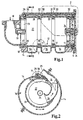
- variable intake manifold shown in Figure 1 is constructed substantially cylindrical, wherein on the one end face an inlet 10 for the filtered intake air and on the other end face a lid 11 having an installation opening for a Shift drum 12 releases, are provided. With the cover removed, the Shift roller 12 are pushed into the interior of the suction tube. This points in the installed state, two bearings 13, with which they are in one Intake manifold housing 14 and in the lid 11 is supported. The cover side bearing has at the same time a receptacle 15 for a drive, not shown Shift drum 12 on.
- the suction tube is intended for the operation of a three-cylinder internal combustion engine.
- Intake passages 16 to the cylinders are formed by parts of the inner wall the suction tube housing 14 and the outer wall of the shift drum 12.
- the suction channels thus extend annularly around the shift drum 12.
- the shift drum 12 consists of a drum 20, which is provided with a closure disc 21 is provided and forms a collector volume in this way. Of the Drum bottom is not closed but consists of spoke-shaped Ribs 23. These ensure that regardless of the angular position of Shift drum 12, the intake air from the inlet 10 into the accumulator volume 22 pass can. Implied screw 24 are used for attachment the closure plate 21 on the drum 20, the lid 11 on the intake manifold 14 and one of the bearings 13 in the closure plate 21st
- the sealing strip is located in a longitudinal groove 29 in the intake manifold 14, which are parallel to the axis of rotation the shift drum 12 extends, and is by a plurality of corrugated springs 30 (see Figure 1) pressed against them shift drum 12.
- the corrugated springs 30 are located in keyways 31, which are separated from each other by separating blocks 32 (see Figure 1).
- FIG. 3 shows the mode of operation of the sealing strip 28. This figure is for explanation and is not a direct subject of the invention.
- the Sealing strip 28 is guided by the longitudinal groove 29 and through in the Fedemut 31 accommodated corrugated springs 30 which are supported in the groove bottom of the longitudinal groove 29, pressed against the shift drum 12. This can be under the sealing strip turn back and forth in the indicated direction of the arrow.
- FIG. 4 shows the mode of action of the sealing ring 17.
- This has an elastic layer 34, which leads to a sealing support of the sealing ring in a cylinder portion 18 of the intake manifold 14 leads.
- a Hose spring 36 housed to the To increase contact pressure of the sealing ring 17 is in an inner ring groove 35 .
- This consists of a coil spring 37, which is fitted together by means of a hose 38 into a ring and is inserted in the inner ring groove 35 in a compressed state. Thereby it reinforces the radially outward pressure of the sealing ring 17.
- On the sealing ring are still on its side edges two Dichtwulste 33 attached. These sealing beads act together with the groove 19 in the shift drum 12 and thereby form a labyrinth seal. in case of an unintentional contact of the sealing beads 33 with the groove flanks, z. By tolerances, the friction is low due to the small bead area.
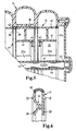
- FIG. 17 An alternative construction of the sealing rings 17 is shown in FIG. These exist of two disks 39, which by an elastic connection 40 on the outer circumference connected to each other.
- the shift drum 12 is at this Design constructed of several discs 41. Sealing rings 17 and Switching disks 41 are changed during installation in the intake manifold housing 14 pushed onto a drive shaft 42. The distance between the Shift discs 41 in the region of the sealing rings 17 by their axial hub length established. The switching discs are on the drive shaft 42 by a Circlip 43 secured against axial slipping. The drive of the drive shaft 42 takes place at the end, not shown.
- the exterior of the indexing disks is connected to the hubs 44 by ribs 23a.
- the interior of the switching disks 41 is used as a collector volume 22. Every second switching disk is radial by means of a feather key connection 47 fixed on the drive shaft 43.
- the switching discs have a bevel gear 45, so that in each case via an unillustrated, fixed housing bevel gear a radially fixed switching disc with the adjacent radial unspecified switching disc communicates in such a way that they are in opposite directions rotate.
- the intake manifold 14 is otherwise described as in Figure 1 built up.
- switching discs 41 and sealing rings 17 are the latter compressed by the switching disks such that between the Disks 39 located, tubular elastic connections 40 against the cylinder sections 18 of the intake manifold 14 are pressed. Thereby These are fixed in the intake manifold, so that when adjusting the Wenntsaugrohres a relative movement between the counter-rotating Shift discs 41 and the sealing rings 17 takes place.
- the sealing ring 17 a at the Last switching disc, which is not inserted between two switching discs, can be designed according to Figure 4.
- FIG. 6 shows an alternative embodiment of a sealing ring 17 according to FIG 5.
- This consists of plastic discs produced by the primary molding process, which are connected by a second elastic component, which is elastic Compound 40 acts.
- the elastic Compound 40 arched outward creating a. Fixation in the intake manifold housing comes about.
- the discs are 39 held together by a snap connection 46.
- the plastic discs each have an annular sealing bead 33, which in the built-in Condition with the not shown switching discs 41 is engaged.
Abstract
Description
Die Erfindung betrifft ein Saugrohr mit einem Schaltelement, insbesondere zur Beeinflussung der Länge verschiedener Rohrabschnitte des Saugrohrs nach der Gattung des Patentanspruches 1.The invention relates to a suction tube with a switching element, in particular for Influencing the length of different pipe sections of the intake manifold after the genus of claim 1.
Schaltsaugrohre sind allgemein bekannt. Durch die zur Verwendung kommenden Schaltelemente werden vorrangig die Längen der Saugkanäle, die den Luftsammler mit den Zylindereinlässen verbinden, beeinflußt. Zu diesem Zweck müssen die Schaltelemente beweglich sein. In den meisten Fällen sind diese daher zylindrisch ausgeführt, wobei durch eine Verdrehung der Schaltelemente die gewünschte Längenänderung im Saugrohr vorgenommen werden kann.Shift suction pipes are well known. By coming to use Switching elements are primarily the lengths of the suction channels, the Air collectors connect with the cylinder inlets, affected. To this end the switching elements must be movable. In most cases these are therefore cylindrical, with a rotation of the switching elements the desired change in length in the intake manifold can be made.
Zur Längenschaltung kommunizieren die Schaltelemente mit den Wandungen
des Saugrohres. Um die akustischen bzw. strömungstechnischen Effekte der
Längenveränderung im Saugrohr nutzen zu können, müssen die zwischen
Saugrohrwandung und Schaltelement entstehenden Spalte möglichst dicht
sein, auch wenn eine absolute Dichtheit nicht notwendig ist, da es hierbei um
Dichtungen zwischen reinluftführenden Kanälen geht. Dies läßt sich durch eine
hohe Maßgenauigkeit der Schaltelemente und der Saugrohrwandungen erzielen
und durch Vorsehen von Dichtungsringen unterstützen. Das Dokument DE
38 07 193 A1 zeigt ein Saugrohr mit einem Einlaß, zylinderseitigem Austritt und
einem Schaltelement, welches eine Schaltwalze bildet und beweglich im Saugrohr
angeordnet ist. Die Schaltwalze dient insbesondere zur Beeinflussung der
Länge verschiedener Rohrabschnitte des Saugrohres. Zur Dichtung sind zwischen
dem Saugrohr und der Schaltwalze Dichtringe, welche in Nuten der
Schaltwalze angeordnet sind, vorgesehen. For length switching, the switching elements communicate with the walls
of the suction pipe. To the acoustic or fluidic effects of
To be able to use length change in the intake manifold, the between
Saugrohrwandung and switching element resulting column as close as possible
be, even if an absolute tightness is not necessary, since this is about
Gaskets between clean air ducts goes. This can be achieved by a
achieve high dimensional accuracy of the switching elements and the Saugrohrwandungen
and assist by providing sealing rings. The
Ein weiteres Beispiel hierfür ist in der DE 44 23 427 A1 angegeben. Es werden
Dichtungsringe vorgeschlagen, die in Nuten in dem zylindrischen Schaltelement
eingebracht werden können und einen größeren Durchmesser aufweisen als
die Einbauöffnung für das Schaltelement. Durch den Einbau des Schaltelements
ergibt sich dadurch eine elastische Deformation der Dichtungsringe, die
zu einer Abdichtung gegen die Saugrohrwandung führt. Die obenstehenden
Dichtungsmöglichkeiten für Schaltelemente im Saugrohr sind jedoch mit hohem
fertigungs- bzw. montagetechnischem Aufwand verbunden. Eine genügende
Maßgenauigkeit von Schaltelement und Saugrohr für eine befriedigende Abdichtung
ist insbesondere bei Schaltsaugrohren aus Kunststoff aufgrund der
Schwindung des Werkstoffes nach dem Gießen nur mit einer aufwendigen
Nachbearbeitung erreichbar. Die in der Schaltwalze untergebrachten Dichtringe
können solche Toleranzen zwar ausgleichen, jedoch erschweren sie die Montage
des Schalelementes in der zugehörigen Einbauöffnung. Denn die Einbauöffnung
weist in vielen Fällen zur Bildung von gekrümmten Ansaugquerschnitten
Durchmessersprünge auf, wobei das Schaltelement nach dem Einbau einen
Wandabschnitt dieser gekrümmten Ansaugquerschnitte bildet. Zur Montage
muß die mit Dichtringen ausgestattete Walze jedoch durch die Hohlräume
geschoben werden, wobei sich die Dichtringe immer wieder auf ihren ursprünglichen
Durchmesser entspannen. Diese müssen dann an außerordentlich
schwer zugänglichen Stellen, wo sich die Dichtspalte zwischen Einbauöffnung
und Schaltelement befinden, auf den Einbaudurchmesser gebracht werden. Bei
Unrundheiten der Einbauöffnung ist im übrigen auch bei Zuhilfenahme von sich
im Schaltelement abstützenden Dichtringen eine vollständige Dichtheit nicht zu
erreichen, da sich diese nicht vollständig an die unrunde Innenkontur der Einbauöffnungen
anpassen können, ohne daß die Verstellkräfte der Schaltwalze
zu hohe Werte annehmen!Another example of this is given in
Die Aufgabe besteht daher darin, ein Saugrohr mit Dichtmitteln zwischen Schaltelement und zugehöriger Einbauöffnung zu schaffen, welches sich ohne Probleme montieren läßt und dabei zu einer optimalen Abdichtung der Rohrabschnitte des Saugrohres untereinander führt wobei, diese Abdichtung weitgehend unabhängig von den am Saugrohr sowie Schaltelement auftretenden Toleranzen ist.The task is therefore a suction tube with sealants between Switching element and associated mounting hole to create, which is without Assemble problems and thereby to an optimal sealing of the pipe sections the suction tube with each other leads, this seal largely regardless of the occurring on the intake manifold and switching element Tolerances is.
Diese Aufgabe wird durch die Merkmale des Patentanspruches 1 gelöst. This object is solved by the features of claim 1.
Das erfindungsgemäße Saugrohr besitzt mindestens ein Schaltelement, welches beweglich im Saugrohr angeordnet ist. Zwischen den Wandungen des Saugrohres und dem Schaltelement entstehen Spalte. Diese Spalte sind durch Dichtmittel abgedichtet, die sich im Saugrohr abstützen, so daß sich eine Relativbewegung zwischen Dichtmittel und Schaltelement bei Bewegung des letzteren ergibt. Die Dichtmittel sind zumindest teilweise elastisch ausgeführt und so gestaltet, daß ihr Einbau zu einer elastischen Deformation der elastischen Teile oder des gesamten Dichtmittels führt. Diese kann genutzt werden, einen Anpressdruck zu erzeugen, der entweder zur Fixierung des Dichtmittels im Saugrohr genutzt wird oder zur Erzielung einer Dichtwirkung zwischen Schaltelement und Dichtmittel. Die Fixierung der Dichtmittel im Saugrohr kann alternativ durch eine formschlüssige Verbindung, insbesondere eine Nut erfolgen. Wichtig ist hierbei, daß der Formschluß die Dichtwirkung der Dichtmittel nicht verhindert, also z. B. die Anpressung der Dichtmittel auf das Schaltelement erlaubt. Werden die Dichtmittel auf das Schaltelement gedrückt, also eine Berührung zwischen diesen Bauteilen erzeugt, so muß der Anpressdruck so niedrig gewählt werden, daß eine Relativbewegung zwischen Dichtmittel und Schaltelement noch möglich ist. Alternativ kann eine berührungslose Dichtung, insbesondere eine Labyrinthdichtung, vorgesehen werden. Die Fixierung der Dichtmittel im Saugrohr kann alternativ zu den oben genannten form- und kraftschlüssigen Verbindungsmöglichkeiten auch stoffschlüssig, insbesondere durch eine Klebverbindung, erfolgen.The intake manifold according to the invention has at least one switching element, which is movably arranged in the suction pipe. Between the walls of the Suction tube and the switching element arise column. These columns are through Sealant sealed, which are supported in the suction tube, so that a relative movement between sealant and switching element during movement of the latter results. The sealing means are at least partially elastic and so designed that their installation to an elastic deformation of the elastic parts or the entire sealant leads. This can be used, a contact pressure to produce, either for fixing the sealant in the intake manifold is used or to achieve a sealing effect between the switching element and sealants. The fixation of the sealant in the intake manifold may alternatively take place by a positive connection, in particular a groove. Important is here that the positive engagement does not prevent the sealing effect of the sealant, So z. B. allows the contact pressure of the sealant on the switching element. If the sealant pressed on the switching element, so a touch generated between these components, the contact pressure must be chosen so low be that a relative movement between the sealant and switching element is still possible. Alternatively, a non-contact seal, in particular a labyrinth seal, be provided. The fixation of the sealant in the intake manifold may alternatively to the above-mentioned positive and non-positive Connection options also cohesive, especially by an adhesive bond, done.
Die oben beschriebenen Dichtmittel sind für grobtolerierte Kunststoffsaugrohre und deren Schaltelemente aus Kunststoff geeignet. Insbesondere können sich vollständig elastisch ausgeführte Dichtringe an die Wandung einer zylindrischen Einbauöffnung zur Aufnahme des Schaltelementes anpassen, wenn diese unrund sind. Dies wird dadurch möglich, daß die Dichtmittel in der zylindrischen Einbauöffnung fixiert werden und sich deshalb bei Verstellung des Schaltelementes nicht mitdrehen müssen. Das erfindungsgemäße Saugrohr kann natürlich auch aus anderen Werkstoffen als Kunststoff, z. B. Aluminium oder Magnesium oder einer Kombination aus diesen Werkstoffen bestehen.The sealants described above are for coarse plastic suction pipes and their switching elements made of plastic suitable. In particular, can completely elastically executed sealing rings on the wall of a cylindrical Adjust mounting hole for receiving the switching element, if this are out of round. This is possible because the sealing means in the cylindrical Installation opening to be fixed and therefore when adjusting the Switching element must not rotate. The intake manifold according to the invention Of course, can also be made of other materials than plastic, z. As aluminum or magnesium or a combination of these materials.
Besonders vorteilhaft ist aus den genannten Gründen eine Gestaltung des Schaltelementes als zylindrischer Körper, insbesondere als Schaltwalze. Durch Unrundheiten der Schaltwalze bzw. der zylindrischen Einbauöffnung entstehen am Umfang unterschiedliche Spaltmaße, die durch die Dichtmittel ausgeglichen werden können. Dies ist insbesondere durch Vorsehen von Nuten in der Schaltwalze erreichbar, wobei die Dichtmittel im Zusammenwirken mit diesen Nuten eine Labyrinthdichtung ergeben. Die für die Schaltwalzen gemachte Aussagen treffen ebenso auf Drehschieber zu.It is particularly advantageous for the reasons mentioned a design of the Switching element as a cylindrical body, in particular as a shift drum. By Out of roundness of the shift drum or the cylindrical mounting hole arise on the circumference different gap dimensions, which are compensated by the sealant can be. This is especially by providing grooves in the Switching drum achievable, wherein the sealing means in cooperation with these Grooves yield a labyrinth seal. The made for the shift drum Statements also apply to rotary valves.
Die Dichtmittel können gemäß einer weiteren Ausgestaltung der Erfindung aber auch als Dichtleisten ausgeführt sein. Die Dichtleisten lassen eine Abdichtung des durch Saugrohrwandung und Schaltelement gebildeten Spaltes entlang einer Graden zu. Entsprechend der Elastizität der Dichtleiste ist auch eine leicht gewundene oder gebogene Form des Dichtspaltes realisierbar. Eine Abdichtung durch Dichtleisten kann z. B. bei Schiebern erfolgen. Weiterhin sind auf diese Weise evtl. Dichtspalte an den Stirnseiten von zylindrischen Schaltelementen abdichtbar. Alternativ kann die Dichtleiste in einer zylindrischen Einbauöffnung parallel verlaufend zu der Drehachse eines zylindrischen Schaltelementes angebracht sein.The sealing means can according to a further embodiment of the invention but Also be designed as a sealing strips. The sealing strips leave a seal along the gap formed by Saugrohrwandung and switching element to a degree. According to the elasticity of the sealing strip is also an easy wound or curved shape of the sealing gap feasible. A seal by sealing strips can z. B. done with sliders. Continue to be on this way possibly sealing gaps on the front sides of cylindrical switching elements sealed. Alternatively, the sealing strip in a cylindrical mounting hole parallel to the axis of rotation of a cylindrical switching element to be appropriate.
Bei zylindrischen Einbauöffnungen ist gemäß einer zweckmäßigen Ausbildung des Erfindungsgedankens der Dichtring kreisringförmig auszuführen. Er kann vorteilhafterweise am Außenumfang eine elastische Lage aufweisen, die nach dem Einbau an den Wandungen des Saugrohrs anliegt und so für eine Fixierung sorgt. Die elastische Lage besteht bevorzugt aus Silikon oder Moosgummi. Um den Anpreßdruck zur Fixierung des Dichtrings an der Saugrohrwand zu erhöhen, kann der Ring mit einem größeren Durchmesser versehen werden, als in der Einbauöffnung zur Verfügung steht. Er muß dann geschlitzt sein, um ihn zum Einbau elastisch deformieren zu können. Der Schlitz kann derart ausgeführt sein, daß sich die Enden des Dichtringes überlappen um auch im geschlitzten Bereich eine optimale Dichtwirkung zu erzielen. Der Schlitz kann auch aus einer Aussparung bestehen, die breit genug ist, um eine Dichtleiste in der zylindrischen Einbauöffnung vorzusehen, die die Dichtringe kreuzt.In cylindrical mounting holes is according to an appropriate training of the inventive idea of the sealing ring to perform annular. He can advantageously on the outer circumference have an elastic layer according to the installation rests against the walls of the suction tube and so for a fixation provides. The elastic layer is preferably made of silicone or foam rubber. To the contact pressure for fixing the sealing ring to the intake manifold to increase the ring can be provided with a larger diameter, as available in the mounting hole. He must then be slotted to to be able to elastically deform it for installation. The slot can be carried out in this way be that overlap the ends of the sealing ring around in the slotted Range to achieve optimum sealing effect. The slot can also consist of a recess that is wide enough to have a sealing strip in provide the cylindrical mounting hole that crosses the sealing rings.
Ist das Saugrohrgehäuse längs geteilt, kann auf den Schlitz in den Dichtringen verzichtet werden. Die Dichtringe können dann vor dem Zusammensetzen der Gehäuseschalen in die Einbauöffnung eingesetzt werden. Die Dichtringe können z.B. aus einem starren Ring bestehen, in den am Außenumfang eine Nut zur Aufnahme eines Dichtringes eingebracht ist. Der Dichtring ist die elastische Lage.If the intake manifold housing is split longitudinally, it may be on the slot in the sealing rings be waived. The sealing rings can then before assembling the Housing shells are inserted into the mounting hole. The sealing rings can e.g. consist of a rigid ring in the outer circumference of a groove is introduced for receiving a sealing ring. The sealing ring is the elastic one Location.
Eine günstige Ausführungsform des Dichtringes sieht vor, diesen am Innenumfang mit einer Schlauchfeder zu versehen. Diese wird beim Einbau des Dichtrings zusammengedrückt und übt dadurch eine nach außen gerichtete Radialkraft auf den Dichtring aus, die für einen zusätzlichen Anpreßdruck des Dichtrings an die Saugrohrwandung sorgt. Der Dichtring kann dann sehr weich ausgeführt werden und sich dadurch Unrundheiten in der zylindrischen Einbauöffnung besonders gut anpassen. Diese Bauform des Dichtrings wird am Besten mit der oben beschriebenen, mit Nuten im Schaltelement zusammenwirkenden Labyrinthdichtung kombiniert. Die Biegeweichheit des Dichtringes kann außer durch eine entsprechende Werkstoffwahl auch durch eine Veränderung des Ringquerschnittes beeinflußt werden.A favorable embodiment of the sealing ring provides, this on the inner circumference to be provided with a hose spring. This is when installing the Sealing ring compressed and thereby exerts an outward Radial force on the sealing ring, which for an additional contact pressure of the Sealing ring to the Saugrohrwandung provides. The sealing ring can then be very soft be executed and thereby out of roundness in the cylindrical mounting hole adapt very well. This design of the sealing ring is on Best with the above-described, with grooves in the switching element cooperating Labyrinth seal combined. The bending softness of the sealing ring can except by a suitable choice of material by a change be influenced of the ring cross-section.
Werden die Dichtmittel dagegen formschlüssig in Nuten der Saugrohrwandungen gelagert, und sollen sie sich zur Erzeugung der Dichtheit auf dem Schaltelement abstützen, ist es vorteilhaft, den Anpreßdruck durch ein elastisches Element zu erzeugen, welches sich in den Nuten in der Saugrohrwandung befindet und im Sinne des Anspruches 1 als Teil der Dichtmittel aufgefaßt wird. Dies kann z. B. durch eine wellenförmige Biegefeder erfolgen. Eine solche Anordnung ist insbesondere für Dichtleisten geeignet, jedoch genauso bei Dichtringen realisierbar.If the sealant, however, form-fitting manner in grooves of Saugrohrwandungen stored, and should they themselves to produce the tightness on the Support switching element, it is advantageous to the contact pressure by an elastic To produce element which is located in the grooves in the Saugrohrwandung located and within the meaning of claim 1 as part of the sealant becomes. This can be z. B. done by a wave-shaped bending spring. Such Arrangement is particularly suitable for sealing strips, but also with Seal can be realized.
Eine weitere Variante der Erfindung sieht vor, den Dichtring aus zwei Scheiben aufzubauen. Diese sind an ihren Außenrändern mit einer elastischen Verbindung versehen. Die Scheiben können aus Stahl sein, wobei als elastische Verbindung insbesondere ein Schlauch zum Einsatz kommt, der mit den Außenrändern der Scheiben verklebt ist. Alternativ hierzu können die Scheiben auch aus Kunststoff bestehen, wobei die elastische Verbindung, bestehend z. B. aus Gummi, in Mehrkomponententechnik an die Außenränder der Scheiben angespritzt ist. Der Einbau der Dichtringe erfolgt durch Einschieben in die zylindrische Einbauöffnung. Diese können im unverformten Zustand bezogen auf den Innendurchmesser der Einbauöffnung mit Untermaß oder leichtem Übermaß gefertigt sein, so daß die Montagekräfte klein sind. Sobald sich der Dichtring an dem vorgesehenem Einbauort befindet wird der Abstand zwischen Scheiben verringert, wodurch sich die elastische Verbindung nach radial außen ausdehnt, bis sie die Wandung der Einbauöffnung erreicht. Eine weitere Annäherung der Scheiben erhöht dann den Anpressdruck des Dichtringes in der Einbauöffnung. Das Verringern des Scheibenabstandes kann z. B. durch ein entsprechendes Montagewerkzeug erfolgen. Alternativ hierzu ist es denkbar, das Schaltelement aus verschiedenen Schaltscheiben aufzubauen, die im Wechsel mit den Dichtringen in die Einbauöffnung gebracht werden. Ein Anpressen der Dichtung an die Rohrwandung kann dann durch Zusammenschieben der Schaltscheiben erfolgen. Hierzu müssen diese einen Anschlag besitzen, der den Scheibenabstand definiert. Dies kann z. B. durch eine Scheibennarbe erfolgen, wobei die Schaltscheiben durch Aufschieben auf eine Welle montiert werden. Am Außenumfang der Schaltscheiben müssen nutartige Schlitze frei bleiben, die mit den Dichtringen zusammenwirken. Durch das Zusammenschieben entsteht zwischen Scheiben der Dichtringe und den angrenzenden Nutflanken der Schaltscheiben eine Dichtwirkung. Another variant of the invention provides, the sealing ring of two discs build. These are at their outer edges with an elastic connection Provided. The discs can be made of steel, being used as an elastic connection In particular, a hose is used, with the outer edges the discs is glued. Alternatively, the discs can also consist of plastic, wherein the elastic compound consisting of z. B. off Rubber, molded in multi-component technology on the outer edges of the discs is. The installation of the sealing rings takes place by insertion into the cylindrical Installation opening. These can in the undeformed state based on the Inner diameter of the mounting hole with undersize or slight oversize be made so that the assembly forces are small. As soon as the sealing ring on the intended installation location is the distance between discs decreases, whereby the elastic compound expands radially outward, until it reaches the wall of the mounting hole. Another approach of Washers then increases the contact pressure of the sealing ring in the mounting hole. The reduction of the distance between the discs can be z. B. by a corresponding Assembly tool done. Alternatively, it is conceivable, the switching element to build from different switching discs, in alternation with the sealing rings be brought into the mounting hole. Pressing the seal on the pipe wall can then by pushing together the switching discs respectively. For this, they must have a stop that the distance between the discs Are defined. This can be z. B. done by a disc color, the Shift discs are mounted by sliding onto a shaft. At the outer circumference the switching discs must remain groove-like slots free with the Interact sealing rings. By pushing together arises between Washers of the sealing rings and the adjacent groove flanks of the switching disks a sealing effect.
Eine besondere Ausführungsform der scheibenförmig aufgebauten Dichtringe sieht vor, daß zwischen den Scheiben eine Schnappverbindung einrastet, die den Dichtring im eingebauten Zustand fixiert. Dies hat den Vorteil, daß die auftretende Reibung zwischen den oben beschriebenen Nutflanken und dem Dichtring minimiert werden kann. Genauso ist eine berührungsfreie Labyrinthdichtung zwischen diesen Bauteilen möglich.A particular embodiment of the disk-shaped sealing rings provides that between the discs a snap connection locks, the fixed the sealing ring in the installed state. This has the advantage that the occurring Friction between the groove flanks described above and the Sealing ring can be minimized. So is a non-contact labyrinth seal between these components possible.
Die Reibung zwischen Dichtmittel und Schaltelement, sofern zwischen diesen Bauteilen eine Berührung vorgesehen ist, kann in vorteilhafter Weise vermindert werden, wenn am Dichtmittel Wulste vorgesehen sind, die mit den Schaltelementen in Berührung stehen. Es ist ebenso möglich die Wulste derart am Schaltelement anzubringen, daß sie mit den Dichtmitteln im Eingriff stehen. Weiterhin können derartige Wulste die Wirkung von Labyrinthdichtungen als Strömungshindernis erhöhen.The friction between sealant and switching element, if between them Components a touch is provided, can be reduced in an advantageous manner are when the sealant beads are provided with the switching elements in contact. It is also possible the bulges so on Attach switching element, that they are engaged with the sealing means. Furthermore, such beads can the effect of labyrinth seals as Increase flow obstruction.
Diese und weitere Merkmale von bevorzugten Weiterbildungen der Erfindung gehen außer aus den Ansprüchen auch aus der Beschreibung und den Zeichnungen hervor, wobei die einzelnen Merkmale jeweils für sich allein oder zu mehreren in Form von Unterkombinationen bei der Ausführungsform der Erfindung und auf anderen Gebieten verwirklicht sein und vorteilhafte sowie für sich schutzfähige Ausführungen darstellen können, für die hier Schutz beansprucht wird.These and other features of preferred embodiments of the invention except from the claims also from the description and drawings show, with the individual features in each case alone or to several in the form of sub-combinations in the embodiment of the invention and in other fields be realized and advantageous as well as for oneself represent protectable versions for which claims protection here becomes.
Weitere Einzelheiten der Erfindung werden in den Zeichnungen anhand von schematischen Ausführungsbeispielen beschrieben. Hierbei zeigen
- Figur 1
- einen Schnitt durch ein Saugrohr mit einer Schaltwalze, die einteilig im Saugrohr montiert wird und eine Dichtleiste sowie vier Dichtringe aufweist, entlang der Drehachse der Schaltwalze,
Figur 2- den Schnitt B-B gemäß Figur 1,
- Figur 3
- das Detail
X aus Figur 2, wobei eine Dichtleiste mit Wellfeder als elastischem Element geschnitten dargestellt ist, - Figur 4
- das Detail Y aus Figur 1, wobei ein Dichtring mit elastischer Lage und Schlauchfeder im Schnitt dargestellt ist,
- Figur 5
- den Ausschnitt eines Saugrohres mit scheibenförmig aufgebauter Schaltwalze und Dichtring, wobei eine Darstellung entsprechend dem Detail Z aus Figur 1 gewählt ist und
- Figur 6
- einen scheibenförmig aufgebauten Dichtring mit elastischer Verbindung der Scheiben und Schnappverbindung.
- FIG. 1
- a section through a suction tube with a shift drum, which is integrally mounted in the intake manifold and having a sealing strip and four sealing rings, along the axis of rotation of the shift drum,
- FIG. 2
- the section BB according to FIG. 1,
- FIG. 3
- the detail X from FIG. 2, wherein a sealing strip with corrugated spring is shown cut as an elastic element,
- FIG. 4
- the detail Y of Figure 1, wherein a sealing ring with elastic layer and hose spring is shown in section,
- FIG. 5
- the detail of a suction tube with disc-shaped shift drum and sealing ring, wherein a representation is selected according to the detail Z of Figure 1 and
- FIG. 6
- a disk-shaped sealing ring with elastic connection of the discs and snap connection.
Das in Figur 1 dargestellte Schaltsaugrohr ist im wesentlichen zylindrisch aufgebaut,
wobei auf der einen Stirnseite ein Einlaß 10 für die gefilterte Ansaugluft
und auf der andem Stirnseite ein Deckel 11, der eine Einbauöffnung für eine
Schaltwalze 12 freigibt, vorgesehen sind. Bei abgenommenem Deckel kann die
Schaltwalze 12 in das Innere des Saugrohres geschoben werden. Diese weist
im eingebauten Zustand zwei Lagerstellen 13 auf, mit denen sie sich in einem
Saugrohrgehäuse 14 bzw. im Deckel 11 abstützt. Die deckelseitige Lagerstelle
weist gleichzeitig eine Aufnahme 15 für einen nicht dargestellten Antrieb der
Schaltwalze 12 auf. The variable intake manifold shown in Figure 1 is constructed substantially cylindrical,
wherein on the one end face an
Das Saugrohr ist für den Betrieb einer Dreizylinderbrennkraftmaschine gedacht.
Ansaugkanäle 16 zu den Zylindern werden gebildet durch Teile der Innenwand
des Saugrohrgehäuses 14 und die Außenwand der Schaltwalze 12. Die Saugkanäle
verlaufen damit ringförmig um die Schaltwalze 12. Eine Abdichtung der
Saugkanäle 16 untereinander und zum restlichen Saugrohrvolumen hin erfolgt
durch Dichtringe 17, die sich in Zylinderabschnitten 18 der Saugrohrinnenwand
abstützen und in ringförmige Nuten 19 in der Schaltwalze 12 eintauchen.The suction tube is intended for the operation of a three-cylinder internal combustion engine.
Die Schaltwalze 12 besteht aus einer Trommel 20, die mit einer Abschlußscheibe
21 versehen ist und auf diese Weise ein Sammlervolumen bildet. Der
Trommelboden ist nicht geschlossen sondern besteht aus speichenförmigen
Rippen 23. Diese gewährleisten, daß unabhängig von der Winkelstellung der
Schaltwalze 12 die Ansaugluft vom Einlaß 10 in das Sammlervolumen 22 gelangen
kann. Angedeutete Schraubverbindungen 24 dienen zur Befestigung
der Abschlußscheibe 21 auf der Trommel 20, dem Deckel 11 auf dem Saugrohrgehäuse
14 und einer der Lagerungen 13 in der Abschlußscheibe 21.The
Der Weg der Ansaugluft vom Sammlervolumen 22 zu den zylinderseitigen
Austritten kann Figur 2 entnommen werden. In das Sammlervolumen 22 ragen
Auslaßstutzen 26, die je einen Durchgang durch die Trommel 20 bilden und in
die Ansaugkanäle 16 münden. Diese Auslaßstutzen enden in Zungen 27, die
sich in den die Ansaugkanäle 16 bildenden Wandabschnitten des Saugrohrgehäuses
14 abstützen. Durch Drehung der Schaltwalze 12 wird dadurch die
Länge der Saugkanäle 16 stufenlos variiert. Diese verjüngen sich zu ihrem Ende
hin und werden dort gegenüber den Austritten 25 durch eine Dichtleiste 28
abgedichtet, um eine Kurzschlußströmung zu verhindern. Die Dichtleiste befindet
sich in einer Längsnut 29 im Saugrohrgehäuse 14, die parallel zur Drehachse
der Schaltwalze 12 verläuft, und wird durch mehrere Wellfedern 30 (siehe
Figur 1) gegen sie Schaltwalze 12 gedrückt. Die Wellfedern 30 befinden sich
in Federnuten 31, die jeweils durch Trennklötze 32 voneinander getrennt sind
(siehe Figur 1). The path of the intake air from the
Der Figur 3 ist die Funktionsweise der Dichtleiste 28 zu entnehmen. Diese Figur
dient der Erläuterung und ist nicht direkter Gegenstand der Erfindung. Die
Dichtleiste 28 wird durch die Längsnut 29 geführt und durch die in der Fedemut
31 untergebrachten Wellfedern 30, die sich im Nutgrund der Längsnut 29 abstützen,
gegen die Schaltwalze 12 gedrückt. Diese kann sich unter der Dichtleiste
in der angedeuteten Pfeilrichtung hin und her drehen. Um die Reibung
zwischen Dichtreiste 28 und Schaltwalze 12 zu minimieren, besitzt die Dichtleiste
zwei Dichtwulste 33, so daß die Auflagefläche auf der Schaltwalze zwei
Strecken entspricht.FIG. 3 shows the mode of operation of the sealing
Der Figur 4 ist die Wirkungsweise des Dichtringes 17 zu entnehmen. Dieser
weist eine elastische Lage 34, die zu einer dichtenden Abstützung des Dichtrings
in einem Zylinderabschnitt 18 des Saugrohrgehäuses 14 führt. Um den
Anpressdruck des Dichtringes 17 zu verstärken, ist in einer Innenringnut 35 eine
Schlauchfeder 36 untergebracht. Diese besteht aus einer Schraubenfeder
37, die mit Hilfe eines Schlauches 38 zu einem Ring zusammengesteckt ist und
in zusammengedrücktem Zustand in die Innenringnut 35 eingebracht ist. Dadurch
verstärkt sie den radial nach außen gerichteten Anpreßdruck des Dichtringes
17. Am Dichtring sind weiterhin an dessen Seitenkanten zwei Dichtwulste
33 angebracht. Diese Dichtwulste wirken zusammen mit der Nut 19 in
der Schaltwalze 12 und bilden dadurch eine Labyrinthdichtung. Im Falle eines
ungewollten Berührens der Dichtwulste 33 mit den Nutflanken, z. B. durch Toleranzen,
ist die Reibung aufgrund der geringen Wulstfläche gering.FIG. 4 shows the mode of action of the sealing
Ein alternativer Aufbau der Dichtringe 17 ist Figur 5 zu entnehmen. Diese bestehen
aus zwei Scheiben 39, die durch eine elastische Verbindung 40 am Außenumfang
miteinander verbunden sind. Die Schaltwalze 12 ist bei dieser
Bauform aus mehreren Schaltscheiben 41 aufgebaut. Dichtringe 17 und
Schaltscheiben 41 werden bei der Montage im Saugrohrgehäuse 14 im Wechsel
auf eine Antriebswelle 42 aufgeschoben. Dabei wird der Abstand der
Schaltscheiben 41 im Bereich der Dichtringe 17 durch ihre axiale Nabenlänge
festgelegt. Die Schaltscheiben werden auf der Antriebswelle 42 durch einen
Sicherungsring 43 gegen axiales Verrutschen gesichert. Der Antrieb der Antriebswelle
42 erfolgt an dem nicht dargestellten Ende.An alternative construction of the sealing rings 17 is shown in FIG. These exist
of two
Das Äußere der Schaltscheiben ist durch Rippen 23a mit den Naben 44 verbunden.
Das Innere der Schaltscheiben 41 wird als Sammlervolumen 22 genutzt.
Jede zweite Schaltscheibe ist durch eine Paßfederverbindung 47 radial
auf der Antriebswelle 43 fixiert. Die Schaltscheiben weisen eine Kegelradverzahnung
45 auf, so daß jeweils über ein nicht dargestelltes, gehäusefestes Kegelzahnrad
eine radial festgelegte Schaltscheibe mit der benachbarten radial
nicht festgelegten Schaltscheibe derart kommuniziert, daß sie sich gegensinnig
drehen. Das Saugrohrgehäuse 14 ist im übrigen wie in Figur 1 beschrieben
aufgebaut.The exterior of the indexing disks is connected to the
Durch die Montage von Schaltscheiben 41 und Dichtringen 17 werden letztere
durch die Schaltscheiben derart zusammengedrückt, daß die zwischen den
Scheiben 39 befindlichen, schlauchförmigen elastischen Verbindungen 40 gegen
die Zylinderabschnitte 18 des Saugrohrgehäuses 14 gedrückt werden. Dadurch
werden diese im Saugrohrgehäuse fixiert, so daß bei Verstellung des
Schaltsaugrohres eine Relativbewegung zwischen den gegenläufig drehenden
Schaltscheiben 41 und den Dichtringen 17 stattfindet. Der Dichtring 17a an der
letzten Schaltscheibe, der nicht zwischen zwei Schaltscheiben eingebracht ist,
kann gemäß Figur 4 gestaltet werden.By installing
Figur 6 zeigt eine alternative Ausgestaltung eines Dichtringes 17 gemäß Figur
5. Dieser besteht aus im Urformverfahren hergestellten Scheiben aus Kunststoff,
die durch eine zweite elastische Komponente verbunden sind, die als elastische
Verbindung 40 fungiert. Bei Annäherung der Scheiben 39 wird die elastische
Verbindung 40 nach außen gewölbt wodurch eine. Fixierung im Saugrohrgehäuse
zustande kommt. Im eingebauten Zustand werden die Scheiben
39 durch eine Schnappverbindung 46 zusammengehalten. Weiterhin weisen
die Kunststoffscheiben je einen ringförmigen Dichtwulst 33 auf, der im eingebauten
Zustand mit den nicht dargestellten Schaltscheiben 41 im Eingriff steht.FIG. 6 shows an alternative embodiment of a sealing
Claims (9)
- Intake manifold, having at least one inlet (10), an outlet (25) on the cylinder side and a switching element (12, 41), which forms a switching roller, the latter more especially serving to influence the length of different tubular portions of the intake manifold,characterised in that the sealing ring (17) has elastically deformable parts to produce contact pressure and is non-displaceably supported in the intake manifold, the elastically deformable parts comprising a resilient layer (34) which abuts against the walls of the intake manifold, and the contact pressure being used either to secure the sealing means in the intake manifold or to achieve a sealing effect between the switching element and the sealing means.circular-ring-shaped gaps with respect to the walls of the intake manifold being formed by the switching roller,the switching roller being displaceable in the intake manifold,at least one sealing ring (17) being disposed in the gaps between the walls and the switching roller and being partially situated in grooves (19) adjacent the gaps,
- Intake manifold according to claim 1, characterised in that the at least one sealing ring (17) has a cutout and a greater diameter in the non-deformed state than in the deformed state when installed in the intake manifold.
- Intake manifold according to claim 2, characterised in that a tubular spring is mounted in the inner face of the at least one sealing ring (17).
- Intake manifold, having at least one inlet (10), an outlet (25) on the cylinder side and a switching element (12, 41), which forms a switching roller, the latter more especially serving to influence the length of different tubular portions of the intake manifold,characterised in that the sealing ring (17) has elastically deformable parts to produce contact pressure and is non-displaceably supported in the intake manifold, the sealing ring comprising two discs (39), a resilient connection (40) being mounted between the outer edges of said discs as elastically deformable parts, the discs (39) having a shorter axial spacing from each other in the installed state than in the uninstalled state, so that the resilient connection in the installed state is deformed radially outwardly and pressed against the walls of the intake manifold.circular-ring-shaped gaps with respect to the walls of the intake manifold being formed by the switching roller,the switching roller being displaceable in the intake manifold,at least one sealing ring (17) being disposed in the gaps between the walls and the switching roller and being partially situated in grooves (19) adjacent the gaps,
- Intake manifold according to claim 4, characterised in that the resilient connection (4) comprises a hose.
- Intake manifold according to one of claims 4 or 5, characterised in that the discs (39) have a snap-fitting connection, and said discs are snapped in position when the sealing ring (17) is in its installed state.
- Intake manifold according to one of the previous claims, characterised in that the sealing means (17,28) do not touch the switching element (12, 41 ).
- Intake manifold according to claim 7, characterised in that the sealing means (17, 28) engage with the grooves (19) in the switching element (12), whereby a labyrinth seal is formed.
- Intake manifold according to one of claims 1 to 6, characterised in that the sealing means (17, 28) have sealing beads (33) which are in contact with the switching element (12, 41).
Applications Claiming Priority (3)
| Application Number | Priority Date | Filing Date | Title |
|---|---|---|---|
| DE19853741A DE19853741A1 (en) | 1998-11-21 | 1998-11-21 | Induction pipe with switching element, has at least partly elastic seals supported motionless in it |
| DE19853741 | 1998-11-21 | ||
| PCT/EP1999/008846 WO2000031391A1 (en) | 1998-11-21 | 1999-11-17 | Suction tube with switching element |
Publications (2)
| Publication Number | Publication Date |
|---|---|
| EP1131547A1 EP1131547A1 (en) | 2001-09-12 |
| EP1131547B1 true EP1131547B1 (en) | 2004-03-10 |
Family
ID=7888547
Family Applications (1)
| Application Number | Title | Priority Date | Filing Date |
|---|---|---|---|
| EP99959282A Expired - Lifetime EP1131547B1 (en) | 1998-11-21 | 1999-11-17 | Suction tube with switching element |
Country Status (9)
| Country | Link |
|---|---|
| US (1) | US6550439B1 (en) |
| EP (1) | EP1131547B1 (en) |
| JP (1) | JP2002530585A (en) |
| KR (1) | KR100602749B1 (en) |
| AT (1) | ATE261545T1 (en) |
| BR (1) | BR9916791A (en) |
| CA (1) | CA2352225A1 (en) |
| DE (2) | DE19853741A1 (en) |
| WO (1) | WO2000031391A1 (en) |
Families Citing this family (5)
| Publication number | Priority date | Publication date | Assignee | Title |
|---|---|---|---|---|
| LU90776B1 (en) * | 2001-05-15 | 2002-11-18 | Delphi Tech Inc | Air intake manifold |
| DE10207431B4 (en) * | 2002-02-21 | 2009-12-31 | Bayerische Motoren Werke Aktiengesellschaft | Multi-function signal lamp of a motor vehicle |
| DE10209180A1 (en) * | 2002-03-01 | 2003-09-18 | Mann & Hummel Filter | Valve for opening and closing a pipe |
| DE10250563B4 (en) * | 2002-10-30 | 2006-04-20 | Pierburg Gmbh | The air intake channel |
| US10856668B2 (en) * | 2017-04-10 | 2020-12-08 | Hill-Rom Services, Inc. | Mattress overlay control system with rotary valves and graphical user interface for percussion and vibration, turn assist and microclimate management |
Family Cites Families (8)
| Publication number | Priority date | Publication date | Assignee | Title |
|---|---|---|---|---|
| DE957802C (en) * | 1954-05-07 | 1957-02-07 | Daimler Benz Ag | Intake line of internal combustion engines |
| DE3446377C2 (en) * | 1983-12-21 | 1994-05-05 | Mazda Motor | Intake device for a piston internal combustion engine |
| DE3807193A1 (en) * | 1988-03-04 | 1989-06-01 | Bayerische Motoren Werke Ag | Intake device for an internal combustion engine |
| DE4423427C2 (en) * | 1994-07-05 | 2000-10-05 | Mann & Hummel Filter | Intake system for a multi-cylinder internal combustion engine |
| DE19528014B4 (en) * | 1995-07-31 | 2010-08-12 | Bayerische Motoren Werke Aktiengesellschaft | Intake system for a V-type internal combustion engine |
| WO1998035146A1 (en) * | 1997-02-05 | 1998-08-13 | Filterwerk Mann + Hummel Gmbh | Suction device for an internal combustion engine |
| DE19712680A1 (en) * | 1997-03-26 | 1998-10-01 | Mann & Hummel Filter | Shift drum, in particular for use in an intake manifold system for a multi-cylinder internal combustion engine |
| JP3484364B2 (en) * | 1998-12-25 | 2004-01-06 | 日産自動車株式会社 | Rotary valve device and engine intake device |
-
1998
- 1998-11-21 DE DE19853741A patent/DE19853741A1/en not_active Withdrawn
-
1999
- 1999-11-17 DE DE59908825T patent/DE59908825D1/en not_active Expired - Fee Related
- 1999-11-17 BR BR9916791-3A patent/BR9916791A/en active Search and Examination
- 1999-11-17 EP EP99959282A patent/EP1131547B1/en not_active Expired - Lifetime
- 1999-11-17 WO PCT/EP1999/008846 patent/WO2000031391A1/en active IP Right Grant
- 1999-11-17 CA CA002352225A patent/CA2352225A1/en not_active Abandoned
- 1999-11-17 JP JP2000584180A patent/JP2002530585A/en not_active Withdrawn
- 1999-11-17 US US09/856,370 patent/US6550439B1/en not_active Expired - Fee Related
- 1999-11-17 AT AT99959282T patent/ATE261545T1/en not_active IP Right Cessation
- 1999-11-17 KR KR1020017006318A patent/KR100602749B1/en not_active IP Right Cessation
Also Published As
| Publication number | Publication date |
|---|---|
| BR9916791A (en) | 2001-08-21 |
| JP2002530585A (en) | 2002-09-17 |
| KR20010093091A (en) | 2001-10-27 |
| US6550439B1 (en) | 2003-04-22 |
| KR100602749B1 (en) | 2006-07-20 |
| DE59908825D1 (en) | 2004-04-15 |
| EP1131547A1 (en) | 2001-09-12 |
| CA2352225A1 (en) | 2000-06-02 |
| ATE261545T1 (en) | 2004-03-15 |
| WO2000031391A1 (en) | 2000-06-02 |
| DE19853741A1 (en) | 2000-05-25 |
Similar Documents
| Publication | Publication Date | Title |
|---|---|---|
| DE3934433C2 (en) | ||
| EP1144078B1 (en) | Round filter cartridge | |
| EP1989467B1 (en) | Toothed wheel arrangement | |
| EP1177826A1 (en) | Replaceable filter cartridge with support member, liquid filter with that filter cartridge | |
| EP1852637A1 (en) | Filter with a radial sealing system | |
| EP1917455A1 (en) | Vibration damper | |
| DE10030037A1 (en) | Cylindrical filter cartridge with support tube | |
| EP1131547B1 (en) | Suction tube with switching element | |
| EP1721095A1 (en) | Sealing device for a radial swivel motor | |
| EP1200722B1 (en) | Throttle device, comprising a butterfly valve for fitting into a flange joint | |
| DE102009042822B4 (en) | slave cylinder | |
| WO2001020144A1 (en) | Shift drum | |
| DE2921669A1 (en) | POETRY | |
| DE19709882B4 (en) | shift drum | |
| EP0748949B1 (en) | Radial support | |
| EP1895185B1 (en) | Separating element, in particular for a damping element of a pneumatic spring | |
| EP1715227A1 (en) | Valve unit | |
| EP0579896A1 (en) | Seal for a slide | |
| EP0825334B1 (en) | Static sealing arrangement for cylindrical housing | |
| WO2018050378A1 (en) | Gas seal | |
| DE19753506C2 (en) | Ring separating piston for a piston-cylinder unit | |
| EP1030963A1 (en) | Induction pipe with insertable components | |
| EP3417192B1 (en) | Shaft seal | |
| DE102021200710A1 (en) | Central slave cylinder for the pneumatic actuation of a friction clutch | |
| DE102006012106B4 (en) | filter element |
Legal Events
| Date | Code | Title | Description |
|---|---|---|---|
| PUAI | Public reference made under article 153(3) epc to a published international application that has entered the european phase |
Free format text: ORIGINAL CODE: 0009012 |
|
| 17P | Request for examination filed |
Effective date: 20010524 |
|
| AK | Designated contracting states |
Kind code of ref document: A1 Designated state(s): AT BE CH CY DE DK ES FI FR GB GR IE IT LI LU MC NL PT SE |
|
| 17Q | First examination report despatched |
Effective date: 20020205 |
|
| REG | Reference to a national code |
Ref country code: GB Ref legal event code: FG4D Free format text: NOT ENGLISH |
|
| GRAP | Despatch of communication of intention to grant a patent |
Free format text: ORIGINAL CODE: EPIDOSNIGR1 |
|
| GRAS | Grant fee paid |
Free format text: ORIGINAL CODE: EPIDOSNIGR3 |
|
| RAP1 | Party data changed (applicant data changed or rights of an application transferred) |
Owner name: MANN + HUMMEL GMBH |
|
| GRAA | (expected) grant |
Free format text: ORIGINAL CODE: 0009210 |
|
| AK | Designated contracting states |
Kind code of ref document: B1 Designated state(s): AT BE CH CY DE DK ES FI FR GB GR IE IT LI LU MC NL PT SE |
|
| PG25 | Lapsed in a contracting state [announced via postgrant information from national office to epo] |
Ref country code: NL Free format text: LAPSE BECAUSE OF FAILURE TO SUBMIT A TRANSLATION OF THE DESCRIPTION OR TO PAY THE FEE WITHIN THE PRESCRIBED TIME-LIMIT Effective date: 20040310 Ref country code: IE Free format text: LAPSE BECAUSE OF FAILURE TO SUBMIT A TRANSLATION OF THE DESCRIPTION OR TO PAY THE FEE WITHIN THE PRESCRIBED TIME-LIMIT Effective date: 20040310 Ref country code: FI Free format text: LAPSE BECAUSE OF FAILURE TO SUBMIT A TRANSLATION OF THE DESCRIPTION OR TO PAY THE FEE WITHIN THE PRESCRIBED TIME-LIMIT Effective date: 20040310 Ref country code: ES Free format text: LAPSE BECAUSE OF FAILURE TO SUBMIT A TRANSLATION OF THE DESCRIPTION OR TO PAY THE FEE WITHIN THE PRESCRIBED TIME-LIMIT Effective date: 20040310 Ref country code: CY Free format text: LAPSE BECAUSE OF FAILURE TO SUBMIT A TRANSLATION OF THE DESCRIPTION OR TO PAY THE FEE WITHIN THE PRESCRIBED TIME-LIMIT Effective date: 20040310 |
|
| REG | Reference to a national code |
Ref country code: CH Ref legal event code: EP |
|
| REG | Reference to a national code |
Ref country code: IE Ref legal event code: FG4D Free format text: GERMAN |
|
| REF | Corresponds to: |
Ref document number: 59908825 Country of ref document: DE Date of ref document: 20040415 Kind code of ref document: P |
|
| PG25 | Lapsed in a contracting state [announced via postgrant information from national office to epo] |
Ref country code: SE Free format text: LAPSE BECAUSE OF FAILURE TO SUBMIT A TRANSLATION OF THE DESCRIPTION OR TO PAY THE FEE WITHIN THE PRESCRIBED TIME-LIMIT Effective date: 20040610 Ref country code: GR Free format text: LAPSE BECAUSE OF FAILURE TO SUBMIT A TRANSLATION OF THE DESCRIPTION OR TO PAY THE FEE WITHIN THE PRESCRIBED TIME-LIMIT Effective date: 20040610 Ref country code: DK Free format text: LAPSE BECAUSE OF FAILURE TO SUBMIT A TRANSLATION OF THE DESCRIPTION OR TO PAY THE FEE WITHIN THE PRESCRIBED TIME-LIMIT Effective date: 20040610 |
|
| GBT | Gb: translation of ep patent filed (gb section 77(6)(a)/1977) |
Effective date: 20040701 |
|
| NLV1 | Nl: lapsed or annulled due to failure to fulfill the requirements of art. 29p and 29m of the patents act | ||
| REG | Reference to a national code |
Ref country code: IE Ref legal event code: FD4D |
|
| PG25 | Lapsed in a contracting state [announced via postgrant information from national office to epo] |
Ref country code: LU Free format text: LAPSE BECAUSE OF NON-PAYMENT OF DUE FEES Effective date: 20041117 Ref country code: AT Free format text: LAPSE BECAUSE OF NON-PAYMENT OF DUE FEES Effective date: 20041117 |
|
| ET | Fr: translation filed | ||
| PG25 | Lapsed in a contracting state [announced via postgrant information from national office to epo] |
Ref country code: LI Free format text: LAPSE BECAUSE OF NON-PAYMENT OF DUE FEES Effective date: 20041130 Ref country code: CH Free format text: LAPSE BECAUSE OF NON-PAYMENT OF DUE FEES Effective date: 20041130 Ref country code: BE Free format text: LAPSE BECAUSE OF NON-PAYMENT OF DUE FEES Effective date: 20041130 |
|
| PLBE | No opposition filed within time limit |
Free format text: ORIGINAL CODE: 0009261 |
|
| STAA | Information on the status of an ep patent application or granted ep patent |
Free format text: STATUS: NO OPPOSITION FILED WITHIN TIME LIMIT |
|
| 26N | No opposition filed |
Effective date: 20041213 |
|
| BERE | Be: lapsed |
Owner name: *MANN + HUMMEL G.M.B.H. Effective date: 20041130 |
|
| REG | Reference to a national code |
Ref country code: CH Ref legal event code: PL |
|
| PGFP | Annual fee paid to national office [announced via postgrant information from national office to epo] |
Ref country code: FR Payment date: 20051110 Year of fee payment: 7 Ref country code: DE Payment date: 20051110 Year of fee payment: 7 |
|
| PGFP | Annual fee paid to national office [announced via postgrant information from national office to epo] |
Ref country code: MC Payment date: 20051114 Year of fee payment: 7 |
|
| PGFP | Annual fee paid to national office [announced via postgrant information from national office to epo] |
Ref country code: GB Payment date: 20051121 Year of fee payment: 7 |
|
| PG25 | Lapsed in a contracting state [announced via postgrant information from national office to epo] |
Ref country code: MC Free format text: LAPSE BECAUSE OF NON-PAYMENT OF DUE FEES Effective date: 20061130 |
|
| PGFP | Annual fee paid to national office [announced via postgrant information from national office to epo] |
Ref country code: IT Payment date: 20061130 Year of fee payment: 8 |
|
| PG25 | Lapsed in a contracting state [announced via postgrant information from national office to epo] |
Ref country code: DE Free format text: LAPSE BECAUSE OF NON-PAYMENT OF DUE FEES Effective date: 20070601 |
|
| GBPC | Gb: european patent ceased through non-payment of renewal fee |
Effective date: 20061117 |
|
| REG | Reference to a national code |
Ref country code: FR Ref legal event code: ST Effective date: 20070731 |
|
| PG25 | Lapsed in a contracting state [announced via postgrant information from national office to epo] |
Ref country code: GB Free format text: LAPSE BECAUSE OF NON-PAYMENT OF DUE FEES Effective date: 20061117 |
|
| BERE | Be: lapsed |
Owner name: *MANN + HUMMEL G.M.B.H. Effective date: 20041130 |
|
| PG25 | Lapsed in a contracting state [announced via postgrant information from national office to epo] |
Ref country code: PT Free format text: LAPSE BECAUSE OF NON-PAYMENT OF DUE FEES Effective date: 20040810 |
|
| PG25 | Lapsed in a contracting state [announced via postgrant information from national office to epo] |
Ref country code: FR Free format text: LAPSE BECAUSE OF NON-PAYMENT OF DUE FEES Effective date: 20061130 |
|
| PG25 | Lapsed in a contracting state [announced via postgrant information from national office to epo] |
Ref country code: IT Free format text: LAPSE BECAUSE OF NON-PAYMENT OF DUE FEES Effective date: 20071117 |