EP1130249A2 - Brennstoffeinspritzventil mit magnetostriktivem Aktor - Google Patents
Brennstoffeinspritzventil mit magnetostriktivem Aktor Download PDFInfo
- Publication number
- EP1130249A2 EP1130249A2 EP01104784A EP01104784A EP1130249A2 EP 1130249 A2 EP1130249 A2 EP 1130249A2 EP 01104784 A EP01104784 A EP 01104784A EP 01104784 A EP01104784 A EP 01104784A EP 1130249 A2 EP1130249 A2 EP 1130249A2
- Authority
- EP
- European Patent Office
- Prior art keywords
- needle
- rod
- fuel
- nozzle body
- injector
- Prior art date
- Legal status (The legal status is an assumption and is not a legal conclusion. Google has not performed a legal analysis and makes no representation as to the accuracy of the status listed.)
- Withdrawn
Links
- 239000000446 fuel Substances 0.000 title claims abstract description 126
- 238000002485 combustion reaction Methods 0.000 claims abstract description 14
- 239000012212 insulator Substances 0.000 claims description 17
- 230000006835 compression Effects 0.000 claims description 10
- 238000007906 compression Methods 0.000 claims description 10
- 230000013011 mating Effects 0.000 claims 3
- 230000000284 resting effect Effects 0.000 claims 2
- XEEYBQQBJWHFJM-UHFFFAOYSA-N Iron Chemical compound [Fe] XEEYBQQBJWHFJM-UHFFFAOYSA-N 0.000 description 4
- 239000000463 material Substances 0.000 description 4
- 238000002347 injection Methods 0.000 description 3
- 239000007924 injection Substances 0.000 description 3
- 230000005611 electricity Effects 0.000 description 2
- 239000012530 fluid Substances 0.000 description 2
- 229910052742 iron Inorganic materials 0.000 description 2
- RYGMFSIKBFXOCR-UHFFFAOYSA-N Copper Chemical group [Cu] RYGMFSIKBFXOCR-UHFFFAOYSA-N 0.000 description 1
- 239000004593 Epoxy Substances 0.000 description 1
- 241001517546 Etrema Species 0.000 description 1
- 229910000831 Steel Inorganic materials 0.000 description 1
- 229910001329 Terfenol-D Inorganic materials 0.000 description 1
- 230000008602 contraction Effects 0.000 description 1
- 238000001816 cooling Methods 0.000 description 1
- 125000004122 cyclic group Chemical group 0.000 description 1
- 238000010586 diagram Methods 0.000 description 1
- 239000002828 fuel tank Substances 0.000 description 1
- ISWSIDIOOBJBQZ-UHFFFAOYSA-N phenol group Chemical group C1(=CC=CC=C1)O ISWSIDIOOBJBQZ-UHFFFAOYSA-N 0.000 description 1
- 239000000565 sealant Substances 0.000 description 1
- 238000007493 shaping process Methods 0.000 description 1
- 238000005476 soldering Methods 0.000 description 1
- 239000010959 steel Substances 0.000 description 1
Images


Classifications
-
- F—MECHANICAL ENGINEERING; LIGHTING; HEATING; WEAPONS; BLASTING
- F02—COMBUSTION ENGINES; HOT-GAS OR COMBUSTION-PRODUCT ENGINE PLANTS
- F02M—SUPPLYING COMBUSTION ENGINES IN GENERAL WITH COMBUSTIBLE MIXTURES OR CONSTITUENTS THEREOF
- F02M61/00—Fuel-injectors not provided for in groups F02M39/00 - F02M57/00 or F02M67/00
- F02M61/16—Details not provided for in, or of interest apart from, the apparatus of groups F02M61/02 - F02M61/14
- F02M61/20—Closing valves mechanically, e.g. arrangements of springs or weights or permanent magnets; Damping of valve lift
-
- F—MECHANICAL ENGINEERING; LIGHTING; HEATING; WEAPONS; BLASTING
- F02—COMBUSTION ENGINES; HOT-GAS OR COMBUSTION-PRODUCT ENGINE PLANTS
- F02M—SUPPLYING COMBUSTION ENGINES IN GENERAL WITH COMBUSTIBLE MIXTURES OR CONSTITUENTS THEREOF
- F02M51/00—Fuel-injection apparatus characterised by being operated electrically
- F02M51/005—Arrangement of electrical wires and connections, e.g. wire harness, sockets, plugs; Arrangement of electronic control circuits in or on fuel injection apparatus
-
- F—MECHANICAL ENGINEERING; LIGHTING; HEATING; WEAPONS; BLASTING
- F02—COMBUSTION ENGINES; HOT-GAS OR COMBUSTION-PRODUCT ENGINE PLANTS
- F02M—SUPPLYING COMBUSTION ENGINES IN GENERAL WITH COMBUSTIBLE MIXTURES OR CONSTITUENTS THEREOF
- F02M51/00—Fuel-injection apparatus characterised by being operated electrically
- F02M51/06—Injectors peculiar thereto with means directly operating the valve needle
- F02M51/0603—Injectors peculiar thereto with means directly operating the valve needle using piezoelectric or magnetostrictive operating means
-
- F—MECHANICAL ENGINEERING; LIGHTING; HEATING; WEAPONS; BLASTING
- F02—COMBUSTION ENGINES; HOT-GAS OR COMBUSTION-PRODUCT ENGINE PLANTS
- F02M—SUPPLYING COMBUSTION ENGINES IN GENERAL WITH COMBUSTIBLE MIXTURES OR CONSTITUENTS THEREOF
- F02M53/00—Fuel-injection apparatus characterised by having heating, cooling or thermally-insulating means
- F02M53/04—Injectors with heating, cooling, or thermally-insulating means
-
- F—MECHANICAL ENGINEERING; LIGHTING; HEATING; WEAPONS; BLASTING
- F02—COMBUSTION ENGINES; HOT-GAS OR COMBUSTION-PRODUCT ENGINE PLANTS
- F02M—SUPPLYING COMBUSTION ENGINES IN GENERAL WITH COMBUSTIBLE MIXTURES OR CONSTITUENTS THEREOF
- F02M55/00—Fuel-injection apparatus characterised by their fuel conduits or their venting means; Arrangements of conduits between fuel tank and pump F02M37/00
- F02M55/002—Arrangement of leakage or drain conduits in or from injectors
-
- F—MECHANICAL ENGINEERING; LIGHTING; HEATING; WEAPONS; BLASTING
- F02—COMBUSTION ENGINES; HOT-GAS OR COMBUSTION-PRODUCT ENGINE PLANTS
- F02M—SUPPLYING COMBUSTION ENGINES IN GENERAL WITH COMBUSTIBLE MIXTURES OR CONSTITUENTS THEREOF
- F02M55/00—Fuel-injection apparatus characterised by their fuel conduits or their venting means; Arrangements of conduits between fuel tank and pump F02M37/00
- F02M55/004—Joints; Sealings
-
- F—MECHANICAL ENGINEERING; LIGHTING; HEATING; WEAPONS; BLASTING
- F02—COMBUSTION ENGINES; HOT-GAS OR COMBUSTION-PRODUCT ENGINE PLANTS
- F02M—SUPPLYING COMBUSTION ENGINES IN GENERAL WITH COMBUSTIBLE MIXTURES OR CONSTITUENTS THEREOF
- F02M61/00—Fuel-injectors not provided for in groups F02M39/00 - F02M57/00 or F02M67/00
- F02M61/04—Fuel-injectors not provided for in groups F02M39/00 - F02M57/00 or F02M67/00 having valves, e.g. having a plurality of valves in series
- F02M61/08—Fuel-injectors not provided for in groups F02M39/00 - F02M57/00 or F02M67/00 having valves, e.g. having a plurality of valves in series the valves opening in direction of fuel flow
-
- F—MECHANICAL ENGINEERING; LIGHTING; HEATING; WEAPONS; BLASTING
- F02—COMBUSTION ENGINES; HOT-GAS OR COMBUSTION-PRODUCT ENGINE PLANTS
- F02M—SUPPLYING COMBUSTION ENGINES IN GENERAL WITH COMBUSTIBLE MIXTURES OR CONSTITUENTS THEREOF
- F02M61/00—Fuel-injectors not provided for in groups F02M39/00 - F02M57/00 or F02M67/00
- F02M61/04—Fuel-injectors not provided for in groups F02M39/00 - F02M57/00 or F02M67/00 having valves, e.g. having a plurality of valves in series
- F02M61/10—Other injectors with elongated valve bodies, i.e. of needle-valve type
-
- F—MECHANICAL ENGINEERING; LIGHTING; HEATING; WEAPONS; BLASTING
- F02—COMBUSTION ENGINES; HOT-GAS OR COMBUSTION-PRODUCT ENGINE PLANTS
- F02M—SUPPLYING COMBUSTION ENGINES IN GENERAL WITH COMBUSTIBLE MIXTURES OR CONSTITUENTS THEREOF
- F02M2200/00—Details of fuel-injection apparatus, not otherwise provided for
- F02M2200/70—Linkage between actuator and actuated element, e.g. between piezoelectric actuator and needle valve or pump plunger
- F02M2200/701—Linkage between actuator and actuated element, e.g. between piezoelectric actuator and needle valve or pump plunger mechanical
- F02M2200/702—Linkage between actuator and actuated element, e.g. between piezoelectric actuator and needle valve or pump plunger mechanical with actuator and actuated element moving in different directions, e.g. in opposite directions
Definitions
- the present invention relates to an electronically-controlled fuel injector for internal combustion engines, and more particularly to fuel injectors suited for the direct injection of high-pressure fuel into the combustion chamber of an internal combustion engine.
- a low voltage solenoid coil is used in combination with an iron rod to restrict or enable fuel delivery from the injector tip.
- the fuel injector includes a piezoelectric component with is activated by a high voltage, low current across its surface to control fuel delivery. Piezoelectric injectors may be operated at high frequency which permits shaping of the fuel delivery profile.
- the present invention includes a unique fuel injector and its application in an internal combustion engine.
- Each embodiment uses an assembly that incorporates a magnetostrictive rod to extend and retract a needle to control fuel expulsion from the injector.
- the fuel injector includes an actuation assembly and a nozzle assembly releasably connected thereto.
- the fuel injector includes a pintle-style needle tip.
- the fuel injector includes a long-stem style needle tip.
- the present invention includes a unique fuel injector and its application in an internal combustion engine, particularly engines having input fuel pressures in the range of about 2,000 psi to about 35,000 psi.
- the fuel injector takes advantage of the particular properties of magnetostrictive materials (e.g., Terfenol-D made by Etrema Products, Inc.) to extend and retract an injector needle in a longitudinal direction.
- magnetostrictive materials e.g., Terfenol-D made by Etrema Products, Inc.
- the fuel injector includes separable components ⁇ an actuation assembly 10 and a nozzle assembly 12. This enables a user to easily replace only a portion of the injector, for example to switch injection heads and/or to replace worn components.
- the injector body is substantially the same.
- the fuel injector is formed as a single unit.
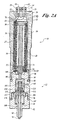
- the actuation assembly 10 includes a generally cylindrical elongate injector body 14 having a first end 16 and a second end 18.
- the injector body 14 further includes a longitudinal bore having a main section 20 defined by a bore shoulder 22 located near the body first end 16. Threads 24 are provided over a portion of the bore located near the body second end 18.
- Various electrical components are provided, including terminals 25, 25' formed in a plug 26 that is adapted to close off the bore opening at the injector body first end 16. In the embodiment of FIGURE 1, this is done by use of a plug 26 capable of being seated upon a bevel 23 formed in the bore near the body first end 16.
- the plug 26 is held seated by washer nuts 29, 29' secured around the terminals 25 and 25'.
- a coil 27 is held within the injector body and is electrically connected to the terminals 25, 25' via insulated wires, 31, 31'.
- the plug 26 is preferably formed of a phenolic insulator material sealed to the body 14 with a sealant.
- the actuation assembly 10 further includes an elongate cylindrical housing 28 sized to fit within the bore main section 20. The upper end of the housing abuts against the bore shoulder 22.
- the housing is formed of steel or other similar materials.
- the housing contains the coil 27, a magnetostrictive rod 36, and an insulator 34.
- the rod 36 is positioned within the coil 27, with the insulator 34 positioned therebetween.
- An epoxy seal may be used between the insulator 34 and the coil 27.
- the upper end of the housing 28 is closed off by an end cap 30.
- the end cap may be integrally formed with the housing 28.
- a small hole 31 is available in the end cap to allow the conductive wires 31, 31' to extend from the terminals 25, 25' to the coil 27 positioned within the housing 28.
- the wires 31, 31' are electrically connected to the terminals, such as by soldering.
- the lower end of the housing is closed off by an output rod 32. In the embodiment shown in FIGURE 1, operative forces are transmitted directly between the output rod 32 and the magnetostrictive rod 36 during use.
- the nozzle assembly 12 includes a nozzle body 50 having a first end 54 and a second end 56.
- the first end 54 includes exterior threads adapted to engage the bore threads 24 of the injector body second end 18.
- a seal 58 may be used, or other shim material, e.g., an annealed copper ring, to ensure the proper placement and seal of the nozzle body 50 relative to the actuation assembly 10.
- a rod-biasing spring 52 is disposed between the uppermost surface of the nozzle body and the output rod 32. In the embodiment shown in FIGURE 1, the rod biasing spring 52 is a Belleville, or disc, spring.
- the force of the nozzle body 50 when threaded into the injector body second end 18, compresses the rod-biasing spring 52 against the output rod 32.
- This arrangement provides a constant compressive force against the magnetostrictive rod 36.
- a designer should verify that the combination of nozzle body 50, rod biasing spring 52, and actuation assembly will continue to apply compression to the magnetostrictive rod throughout its operative cycle.
- the Belleville spring provides a preloading force of about 250 lbs. In another embodiment, force is provided sufficient to compress the rod 36 a distance in the range of about 0.002 inches to about 0.0025 inches.
- the nozzle body 50 further includes a longitudinal hole 59 and a concentric, larger-diameter cavity 61 located near the nozzle body first end 54.
- An injection needle 60 is held within the longitudinal hole 59 and is biased in an upward direction by a spring 62 located within the cavity 61. The spring pushes against a spring retainer 64 attached to the upper end of the needle 60 by a retainer clip 66.
- a fuel input port 68 is available to receive high pressure fuel from a fuel pump.
- a pintle-style nozzle tip 72 includes fuel expulsion holes 70, 70'.
- a portion 73 of the needle 60 has a diameter that is appreciably less than the adjacent diameter of the longitudinal hole 59.
- the fuel input port 68 connects to this region of the needle so that fuel may flow around needle portion 73 during use.
- the lower end of the nozzle tip includes fuel expulsion hole(s) 70.
- a constricting bevel 75 is formed in the hole 59 near the tip holes 70.
- the needle 60 includes a shoulder 77 sized to mate with the constricting bevel 75. In the retracted position, the contact between the bevel 75 and shoulder 77 prohibits fuel flow from the holes 70. In the extended position, fuel passes between the bevel and shoulder to exit the tip 72. This is similar to pintle-style configurations, however, with the needle arranged to move downward to open.
- the spring 62 pushes against the needle retainer 64 to push the needle 60 upward against the output rod 32. This lifts the needle lower end shoulder 77 to contact the constricting bevel 75 to block fuel from flowing out the holes 70'.
- a magnetic field is created which causes the magnetostrictive rod 36 to expand against the output rod 32. This further causes compression of the rod biasing spring 52 and downward motion of the needle 60. Downward motion of the needle 60 separates the needle lower end from the body hole 59, thereby allowing high-pressure fuel to pass out the fuel expulsion holes 70.
- expansion and contraction distance of the rod 60 is in the range of about 0.0005 to about 0.003, a preferred amount being about 0.001 inches.
- the embodiment of FIGURE 1 includes provision to allow high-pressure fuel to leak, in small amounts, out of the nozzle body 50, into the actuation assembly 10, and out of the actuation assembly 10 to a collection area.
- This fuel helps to cool injector components.
- fuel is allowed to pass in small quantity up the needle 60 into the cavity 61. From there, fuel can pass through a small hole 76 in the output rod 32, move through the housing 28 and out the housing upper hole 31. Fuel moving through the housing 28 is thus available to cool the coil 27 and the magnetostrictive rod 36. Fuel exits the injector body first end 16 through a fuel drain passage 78.
- Other arrangements may be used should a designer want to avoid fuel leakage or provide alternative means of cooling.
- FIGURE 2A a second embodiment of a fuel injector formed in accordance with the present invention is provided.
- the embodiment of FIGURE 2A is a "Bosch" style needle nozzle, or more generically, a long-stem hole style nozzle.
- the nozzle assembly 12 of FIGURE 2A is connected to the injector body second end 18.
- a rod-biasing spring 52 e.g., a Belleville spring
- two springs 52 and 52' may be used for additional compressive strength.
- Seals 58, or shims seal the seam between the injector body 14 and the nozzle assembly 12.
- the Bosch-style nozzle assembly of FIGURE 2A requires components to bias a needle 60' in a downward direction. This is accomplished using a nozzle assembly having a first portion 90 and a second lower portion 92.
- the second portion 92 is connected to the lower end of the first portion 90 in a manner similar to the connection of the first portion 90 with the injector body second end 18.
- the first portion 90 includes a cavity 94 opening downward.
- the second portion 92 also includes a cavity 96, though opening upward. As assembled, the cavities 94 and 96 are adjacent to one another.
- a plunger 98 is disposed within the first portion 90.
- a plunger pin 100 extends longitudinally within the first portion 90 to transmit loads between the plunger 98 and the lower surface of the output rod 32.
- the plunger 98 has an internal space 102 that extends from the lowermost surface of the plunger 98 up into the plunger body a distance.
- the second portion 92 includes a trap 106 supported by a needle case 108.
- the trap 106 is disposed substantially within the second portion cavity 96.
- the needle case 108 is partially disposed within the cavity 96 and partially extended out the second portion 92 lower end.
- the needle 60' is held within the needle case 108 and further extends up through the trap 106 and into the internal space 102 of the plunger 98.
- a needle retainer such as nut 110 is connected to the upper end of the needle 60' within the internal space 102.
- a ring spring 112 Positioned between the lowermost surface of the plunger 98 and the uppermost surface of the trap 106 is a ring spring 112 (referred to herein generically as a radial spring).
- the ring spring 112 has a flat upper surface and a flat lower surface. Extending downward from the lower surface are a number of rocker arms 120, 120', 120". The rocker arms extend toward the center of the ring spring. Each rocker arm includes a line of pivot 122, 122', 122" on its underside.
- the radial, or ring spring, arrangement allows for relative motion between its circumference and the interior portion of each rocker arm.
- an opening in the center of the ring spring 112 allows the needle 60' to extend through the ring spring and allows the nut 110 to rest on the upper surface of the ring spring 112.
- a needle-biasing spring 114 is held in compression between the nut 110 and the uppermost surface of the plunger internal space 102.
- a fuel expulsion opening 70 is formed in the lowermost end of the nozzle case 108 as is conventional in Bosch-style needle tips.
- a fuel input port 68 is provided in the first portion 90. High pressure fuel reaches the fuel expulsion hole 70 by passing from the input port 68 through the first portion cavity 94.
- the trap 106 includes a circular groove 113 on its underside and a passage 115 extending through the trap to the groove 113. The passage and groove allow fuel to travel through the trap to reach the interior of the needle case 108 in the spaces surrounding the needle 60'.
- the output rod 32 is biased upward against the magnetostrictive rod 36 by the compression in rod-biasing springs 52, 52'.
- the lower surface of the plunger rests against the ring spring upper perimental surface.
- the plunger is pressed against the plunger pin 100 at the plunger upper surface, while the needle retaining spring 114 pushes the nut 110 and needle 60' downward against the inner radial portions of the ring spring arms.
- the pivot points 122, 122', and 122" rest against the upper surface of the trap 106.
- the magnetostrictive rod 36 expands slightly to push the output rod 32 downward against the pin 100 which in turn pushes against the plunger 98.
- the lower surface of plunger 98 pushes on the upper outer edge of the spring 112 causing pivotal motion of the ring spring 112 to lift the nut 110 against the bias of the needle-biasing spring 114. Movement of the nut 110 causes corresponding upward movement of the needle 60' and corresponding opening of the fuel expulsion hole 70.
- Internal fuel flow up through the injector is possible as provided in the first embodiment.
- a seal 69 prohibits fuel leakage between the needle case 108 and the nozzle body lower portion 92.
- FIGURES 2C and 2D illustrate an alternative embodiment of a radial spring.
- the trap 106 is thicker and includes a number of arcuate troughs 119 extending into the trap upper surface and positioned radially therein at equal angular distances. See FIGURE 2D.
- a key 117 is placed in each trough 119.
- Each key includes a flat upper surface and an arcuate lower surface sized to mate with its corresponding trough 119.
- the plunger lower surface pushes against the outer end of the keys.
- the keys rotate within their troughs causing the keys' inner end to push upward on the nut 110. This action thereby lifts the needle 60' and permits expulsion of fuel.
- FIGURE 3A A third embodiment of a fuel injector formed in accordance with the present invention is provided in FIGURE 3A in which an injector includes a combined actuation and nozzle assembly 200.
- the assembly 200 includes a housing 212 with a first end 214 and a second end 216.
- the injector housing 212 includes a longitudinal bore.
- An injector cap 218 closes off the bore at the housing first end 214.
- the injector cap includes cavity 220 extending partway into the injector cap from the undersurface thereof.
- An actuation container 222 is formed as an elongate cylinder and is held within the housing 212. Within the actuation container 222, a coil 27, an insulator 34, and a magnetostrictive rod 36' are contained.
- the magnetostrictive rod 36' of FIGURE 3B includes an inner passage 224.
- An elongate needle 60" is located within the inner passage 224. The needle upper end extends out the magnetostrictive rod 36' and up into the cavity 220 of the injector cap 218.
- a retainer 226 is attached to the upper end of the needle 60' and is held in place by a retainer clip 228.
- An output rod 232 is positioned between the uppermost end of the magnetostrictive rod 36' and the lower surface of the retainer 226.
- a Belleville spring or other rod-biasing spring 52 is compressed between the upper surface of the output rod 232 and the lower surface of the injector cap 218, with the needle 60" extending up through the magnetostrictive rod 36' and through the center of the output rod 232.
- Electric current is provided by wires that are placed through side openings 234 formed in the housing 212 and through the actuation container 222. Fittings 236 with seals 238 close off the side openings 234.
- a needle case 240 is located below the lower end of the actuation container 222.
- the needle case 240 extends out the bottom of the housing 212.
- a high-pressure fuel input port 68 is formed in the housing 212 and connects with an input line 242 formed in the lower portion of the actuation container 222.
- the needle 60" at this location is of a smaller diameter than elsewhere. This allows high pressure fluid to travel around the needle 60' and downward to a fuel expulsion hole 70.
- FIGURE 4 is a schematic illustration of an internal combustion engine system formed in accordance with the present invention, including the use of a fuel injector such as described above.
- the engine 300 is in communication with a controller 302 and a fuel pump 304.
- the pump provides high pressure fuel from a fuel tank 306 to the fuel injector 10 while the controller 302 provides timed voltage to activate the coil of the fuel injector 10.
Applications Claiming Priority (2)
| Application Number | Priority Date | Filing Date | Title |
|---|---|---|---|
| US515342 | 2000-02-29 | ||
| US09/515,342 US6279842B1 (en) | 2000-02-29 | 2000-02-29 | Magnetostrictively actuated fuel injector |
Publications (1)
| Publication Number | Publication Date |
|---|---|
| EP1130249A2 true EP1130249A2 (de) | 2001-09-05 |
Family
ID=24050945
Family Applications (1)
| Application Number | Title | Priority Date | Filing Date |
|---|---|---|---|
| EP01104784A Withdrawn EP1130249A2 (de) | 2000-02-29 | 2001-02-27 | Brennstoffeinspritzventil mit magnetostriktivem Aktor |
Country Status (3)
| Country | Link |
|---|---|
| US (1) | US6279842B1 (de) |
| EP (1) | EP1130249A2 (de) |
| CZ (1) | CZ2001733A3 (de) |
Cited By (17)
| Publication number | Priority date | Publication date | Assignee | Title |
|---|---|---|---|---|
| DE10149915A1 (de) * | 2001-10-10 | 2003-04-24 | Bosch Gmbh Robert | Brennstoffeinspritzventil |
| WO2003040538A1 (de) * | 2001-10-31 | 2003-05-15 | Robert Bosch Gmbh | Verfahren zum einspritzen von brennstoff |
| WO2003069152A1 (de) * | 2002-02-13 | 2003-08-21 | Siemens Aktiengesellschaft | Dichtungselement für den piezoaktor eines kraftstoff-einspritzventils |
| DE10254186A1 (de) * | 2002-11-20 | 2004-06-17 | Siemens Ag | Injektor mit einer direkt angetriebenen Register-Düsennadel für die Kraftstoffeinspritzung in einen Verbrennungsmotor |
| WO2004074672A1 (de) * | 2003-02-19 | 2004-09-02 | Siemens Aktiengesellschaft | Einspritzventil für die einspritzung von kraftstoff in eine verbrennungskraftmaschine |
| WO2005014995A1 (de) * | 2003-08-07 | 2005-02-17 | Robert Bosch Gmbh | Injektor für kraftstoff-einspritzsysteme von brennkraftmaschinen, insbesondere von direkteinspritzenden dieselmotoren |
| WO2005073547A1 (de) * | 2004-01-30 | 2005-08-11 | Robert Bosch Gmbh | Kabeldurchführung und brennstoffsystemteil mit einer kabeldurchführung |
| EP1533517A3 (de) * | 2003-11-14 | 2006-02-01 | Magneti Marelli Powertrain S.p.A. | Kraftstoffeinspritzventil mit hydraulischem Stift |
| EP1741921A1 (de) * | 2005-07-04 | 2007-01-10 | Hitachi, Ltd. | Brennstoffeinspritzventil |
| EP1712774A3 (de) * | 2005-04-11 | 2007-05-02 | Robert Bosch Gmbh | Brennstoffeinspritzventil |
| DE102004042352B4 (de) * | 2004-08-20 | 2007-08-09 | Siemens Ag | Kraftstoffinjektor für eine Brennkraftmaschine |
| DE102004059104B4 (de) * | 2004-08-20 | 2007-09-06 | Siemens Ag | Abdichtungsanordnung eines Piezoaktors für einen Kraftstoffinjektor sowie Verfahren zur Montage eines Kraftstoffinjektors |
| EP2105603A1 (de) * | 2008-03-27 | 2009-09-30 | Continental Automotive GmbH | Aktuatoranordnung und Einspritzventil |
| EP2444650A1 (de) * | 2010-10-20 | 2012-04-25 | Delphi Technologies Holding S.à.r.l. | Verbesserter Kraftstoffeinspritzventil |
| WO2013026611A1 (de) * | 2011-08-25 | 2013-02-28 | Robert Bosch Gmbh | Injektor für ein fluid mit einer fluidzuführung |
| WO2015169500A1 (en) * | 2014-05-07 | 2015-11-12 | Delphi International Operations Luxembourg S.À R.L. | Connector assembly for a fuel injector |
| EP3084853A4 (de) * | 2013-12-19 | 2017-07-26 | Great Plains Diesel Technologies, L.C. | Kraftstoffdruckerkennung durch einen schnellen magnetostriktiven aktor |
Families Citing this family (34)
| Publication number | Priority date | Publication date | Assignee | Title |
|---|---|---|---|---|
| DE19921242C1 (de) * | 1999-05-07 | 2000-10-26 | Siemens Ag | Verfahren zum Positionieren des Stellantriebs in einem Kraftstoffinjektor und Vorrichtung zur Durchführung des Verfahrens |
| JP2001234830A (ja) * | 2000-02-28 | 2001-08-31 | Hirohisa Tanaka | 内燃機関用蓄圧式燃料噴射装置 |
| EP1132615B1 (de) * | 2000-03-07 | 2006-11-08 | Matsushita Electric Industrial Co., Ltd. | Flüssigkeitsspender |
| JP3827307B2 (ja) * | 2000-07-21 | 2006-09-27 | シーメンス ヴィディーオー オートモーティヴ コーポレイション | テルビウム系希土類磁歪合金の温度特性の金属学的及び機械的補償 |
| JP2002119075A (ja) * | 2000-10-03 | 2002-04-19 | Matsushita Electric Ind Co Ltd | アクチュエータ装置 |
| US6543700B2 (en) * | 2000-12-11 | 2003-04-08 | Kimberly-Clark Worldwide, Inc. | Ultrasonic unitized fuel injector with ceramic valve body |
| US6622487B2 (en) * | 2001-01-16 | 2003-09-23 | Rolls-Royce Plc | Fluid flow control valve |
| DE50212908D1 (de) * | 2001-08-17 | 2008-11-27 | Continental Automotive Gmbh | Aktor als antriebseinheit für einen injektor sowie verfahren zur herstellung des injektors |
| US20030168936A1 (en) * | 2001-11-08 | 2003-09-11 | Everingham Gary M. | Electro-active polymer as a fuel vapor control valve actuator |
| DE50305852D1 (de) * | 2002-04-04 | 2007-01-11 | Siemens Ag | Einspritzventil |
| DE10245109A1 (de) * | 2002-09-27 | 2004-04-08 | Siemens Ag | Injektor, insbesondere Kraftstoff-Einspritzventil, mit einem piezoelektrischen Aktor |
| US6640784B1 (en) | 2002-10-09 | 2003-11-04 | Robert Bosch Corporation | Spark ignition direct injection system |
| US6811093B2 (en) * | 2002-10-17 | 2004-11-02 | Tecumseh Products Company | Piezoelectric actuated fuel injectors |
| US20040089750A1 (en) * | 2002-10-23 | 2004-05-13 | Muniswamappa Anjanappa | Micro-array fluid dispensing apparatus and method |
| EP1420456B1 (de) * | 2002-11-13 | 2013-05-22 | Oki Data Corporation | Monolithisches Halbleiterbauelement und optischer Druckkopf |
| FR2854664B1 (fr) * | 2003-05-09 | 2006-06-30 | Renault Sa | Dispositif d'injection de fluide |
| JP4002229B2 (ja) * | 2003-10-03 | 2007-10-31 | 株式会社日立製作所 | 燃料噴射弁 |
| US7240856B2 (en) * | 2003-10-24 | 2007-07-10 | Keihin Corporation | Fuel injection control device |
| DE602004030419D1 (de) * | 2004-02-27 | 2011-01-20 | Continental Automotive Italy S P A | Flüssigkeitsinjektor |
| US7255290B2 (en) * | 2004-06-14 | 2007-08-14 | Charles B. Bright | Very high speed rate shaping fuel injector |
| DE102005024710A1 (de) * | 2005-05-30 | 2006-12-07 | Robert Bosch Gmbh | Brennstoffeinspritzventil |
| DE102005051438A1 (de) * | 2005-10-27 | 2007-05-03 | Daimlerchrysler Ag | Kraftstoffinjektor für eine Brennkraftmaschine |
| JP4582061B2 (ja) * | 2006-07-04 | 2010-11-17 | 株式会社デンソー | ピエゾインジェクタ及びインジェクタ駆動システム |
| US7469878B1 (en) | 2006-09-01 | 2008-12-30 | The United States Of America As Represented By The Administrator Of The National Aeronautics And Space Administration | Magnetostrictive valve assembly |
| US7721716B1 (en) | 2008-07-16 | 2010-05-25 | Harwood Michael R | High pressure piezoelectric fuel injector |
| DE102008037788A1 (de) * | 2008-08-14 | 2010-02-25 | Continental Automotive Gmbh | Ausgleichsvorrichtung und Einspritzventil |
| US7849836B2 (en) * | 2008-10-07 | 2010-12-14 | Caterpillar Inc | Cooling feature for fuel injector and fuel system using same |
| US8464750B1 (en) * | 2010-06-30 | 2013-06-18 | The United States Of America As Represented By The Administrator Of The National Aeronautics And Space Administration | Magnetostrictive pressure regulating system |
| US8418676B2 (en) * | 2010-08-10 | 2013-04-16 | Great Plains Diesel Technologies, L.C. | Programmable diesel fuel injector |
| US8608127B2 (en) * | 2011-01-24 | 2013-12-17 | Fluke Corporation | Piezoelectric proportional control valve |
| US9284930B2 (en) | 2011-06-03 | 2016-03-15 | Michael R. Harwood | High pressure piezoelectric fuel injector |
| DE102011087005A1 (de) * | 2011-11-24 | 2013-05-29 | Robert Bosch Gmbh | Ventil zum Zumessen eines strömenden Mediums |
| US20140054396A1 (en) * | 2012-08-21 | 2014-02-27 | International Engine Intellectual Property Company, Llc | Fluid injector |
| US9341154B2 (en) * | 2014-04-10 | 2016-05-17 | Continental Automotive Gmbh | Valve assembly for a fuel injector and fuel injector |
Family Cites Families (14)
| Publication number | Priority date | Publication date | Assignee | Title |
|---|---|---|---|---|
| US2721100A (en) * | 1951-11-13 | 1955-10-18 | Jr Albert G Bodine | High frequency injector valve |
| US4782794A (en) | 1986-08-18 | 1988-11-08 | General Electric Company | Fuel injector system |
| DE3808671A1 (de) | 1987-03-13 | 1988-09-22 | Orbital Eng Pty | Vorrichtung und verfahren zur kraftstoffeinspritzung |
| EP0571003B1 (de) | 1987-12-02 | 1997-07-16 | Ganser-Hydromag Ag | Elektromagnetisch betätigbare Vorrichtung zum schnellen Umschalten eines elektro-hydraulisch betätigten Kraftstoffeinspritzventils |
| DE3936619A1 (de) * | 1989-11-03 | 1991-05-08 | Man Nutzfahrzeuge Ag | Verfahren zum einspritzen eines brennstoffes in einen brennraum einer luftverdichtenden, selbstzuendenden brennkraftmaschine, sowie vorrichtungen zur durchfuehrung dieses verfahrens |
| US5163463A (en) | 1990-07-19 | 1992-11-17 | Fisher Controls International, Inc. | Mechanical flexure for motion amplification and transducer with same |
| US5244180A (en) | 1992-09-03 | 1993-09-14 | Siemens Automotive L.P. | Solenoid pre-loader |
| IT1261149B (it) | 1993-12-30 | 1996-05-09 | Elasis Sistema Ricerca Fiat | Valvola di dosaggio per il comando dell'otturatore di un iniettore di combustibile |
| US5501425A (en) | 1994-09-21 | 1996-03-26 | Marotta Scientific Controls, Inc. | Magnetostrictively actuated valve |
| US5645226A (en) | 1995-02-13 | 1997-07-08 | Siemens Automotive Corporation | Solenoid motion initiator |
| US5719791A (en) | 1995-03-17 | 1998-02-17 | Georgia Tech Research Corporation | Methods, apparatus and systems for real time identification and control of modes of oscillation |
| US5868375A (en) | 1995-10-11 | 1999-02-09 | Marotta Scientific Controls, Inc. | Magnetostrictively actuated valve |
| US5900690A (en) | 1996-06-26 | 1999-05-04 | Gipson; Lamar Heath | Apparatus and method for controlling an ultrasonic transducer |
| IT1289794B1 (it) | 1996-12-23 | 1998-10-16 | Elasis Sistema Ricerca Fiat | Perfezionamenti ad una valvola di dosaggio a comando elettromagnetico per un iniettore di combustibile. |
-
2000
- 2000-02-29 US US09/515,342 patent/US6279842B1/en not_active Expired - Fee Related
-
2001
- 2001-02-27 CZ CZ2001733A patent/CZ2001733A3/cs unknown
- 2001-02-27 EP EP01104784A patent/EP1130249A2/de not_active Withdrawn
Cited By (27)
| Publication number | Priority date | Publication date | Assignee | Title |
|---|---|---|---|---|
| DE10149915A1 (de) * | 2001-10-10 | 2003-04-24 | Bosch Gmbh Robert | Brennstoffeinspritzventil |
| WO2003040538A1 (de) * | 2001-10-31 | 2003-05-15 | Robert Bosch Gmbh | Verfahren zum einspritzen von brennstoff |
| WO2003069152A1 (de) * | 2002-02-13 | 2003-08-21 | Siemens Aktiengesellschaft | Dichtungselement für den piezoaktor eines kraftstoff-einspritzventils |
| US7097484B2 (en) | 2002-02-13 | 2006-08-29 | Siemens Aktiengesellschaft | Sealing element for the piezo actuator of a fuel injection valve |
| DE10254186A1 (de) * | 2002-11-20 | 2004-06-17 | Siemens Ag | Injektor mit einer direkt angetriebenen Register-Düsennadel für die Kraftstoffeinspritzung in einen Verbrennungsmotor |
| WO2004074672A1 (de) * | 2003-02-19 | 2004-09-02 | Siemens Aktiengesellschaft | Einspritzventil für die einspritzung von kraftstoff in eine verbrennungskraftmaschine |
| WO2005014995A1 (de) * | 2003-08-07 | 2005-02-17 | Robert Bosch Gmbh | Injektor für kraftstoff-einspritzsysteme von brennkraftmaschinen, insbesondere von direkteinspritzenden dieselmotoren |
| EP1775458A2 (de) * | 2003-11-14 | 2007-04-18 | Magneti Marelli Powertrain S.p.A. | Kraftstoffeinspritzventil mit hydraulischem Stift |
| EP1775458A3 (de) * | 2003-11-14 | 2007-10-17 | Magneti Marelli Powertrain S.p.A. | Kraftstoffeinspritzventil mit hydraulischem Stift |
| EP1533517A3 (de) * | 2003-11-14 | 2006-02-01 | Magneti Marelli Powertrain S.p.A. | Kraftstoffeinspritzventil mit hydraulischem Stift |
| US7191963B2 (en) | 2003-11-14 | 2007-03-20 | Magneti Marelli Powertrain S.P.A. | Fuel injector with hydraulic pin actuation |
| WO2005073547A1 (de) * | 2004-01-30 | 2005-08-11 | Robert Bosch Gmbh | Kabeldurchführung und brennstoffsystemteil mit einer kabeldurchführung |
| US7793863B2 (en) | 2004-08-20 | 2010-09-14 | Continental Automotive Gmbh | Fuel injector for an internal combustion engine |
| DE102004042352B4 (de) * | 2004-08-20 | 2007-08-09 | Siemens Ag | Kraftstoffinjektor für eine Brennkraftmaschine |
| DE102004059104B4 (de) * | 2004-08-20 | 2007-09-06 | Siemens Ag | Abdichtungsanordnung eines Piezoaktors für einen Kraftstoffinjektor sowie Verfahren zur Montage eines Kraftstoffinjektors |
| EP1712774A3 (de) * | 2005-04-11 | 2007-05-02 | Robert Bosch Gmbh | Brennstoffeinspritzventil |
| EP1741921A1 (de) * | 2005-07-04 | 2007-01-10 | Hitachi, Ltd. | Brennstoffeinspritzventil |
| EP2105603A1 (de) * | 2008-03-27 | 2009-09-30 | Continental Automotive GmbH | Aktuatoranordnung und Einspritzventil |
| EP2444650A1 (de) * | 2010-10-20 | 2012-04-25 | Delphi Technologies Holding S.à.r.l. | Verbesserter Kraftstoffeinspritzventil |
| WO2012052295A1 (en) | 2010-10-20 | 2012-04-26 | Delphi Technologies Holding S.À.R.L. | Improved fuel injector |
| CN103168164A (zh) * | 2010-10-20 | 2013-06-19 | 德尔福技术控股有限公司 | 改进的燃料喷射器 |
| CN103168164B (zh) * | 2010-10-20 | 2015-10-21 | 德尔福国际运营卢森堡有限公司 | 改进的燃料喷射器 |
| US9822744B2 (en) | 2010-10-20 | 2017-11-21 | Delphi International Operations Luxembourg S.A.R.L. | Fuel injector |
| WO2013026611A1 (de) * | 2011-08-25 | 2013-02-28 | Robert Bosch Gmbh | Injektor für ein fluid mit einer fluidzuführung |
| EP3084853A4 (de) * | 2013-12-19 | 2017-07-26 | Great Plains Diesel Technologies, L.C. | Kraftstoffdruckerkennung durch einen schnellen magnetostriktiven aktor |
| WO2015169500A1 (en) * | 2014-05-07 | 2015-11-12 | Delphi International Operations Luxembourg S.À R.L. | Connector assembly for a fuel injector |
| US10527015B2 (en) | 2014-05-07 | 2020-01-07 | Delphi Technologies Ip Limited | Connector assembly for a fuel injector |
Also Published As
| Publication number | Publication date |
|---|---|
| US6279842B1 (en) | 2001-08-28 |
| CZ2001733A3 (cs) | 2002-10-16 |
Similar Documents
| Publication | Publication Date | Title |
|---|---|---|
| US6279842B1 (en) | Magnetostrictively actuated fuel injector | |
| US4101076A (en) | Piezoelectric fuel injector valve | |
| US7267111B2 (en) | Fuel injector | |
| US6520423B1 (en) | Hydraulic intensifier assembly for a piezoelectric actuated fuel injector | |
| JP2007510849A (ja) | 内燃機関の燃焼室内に燃料を噴射するインジェクタ、特にピエゾアクチュエータによって制御されるコモンレール・インジェクタ | |
| US6454239B1 (en) | Valve for controlling liquids | |
| KR890001734B1 (ko) | 내연기관의 연료분사 노즐장치 | |
| KR20010042456A (ko) | 연료를 가압하기 위한 차동 피스톤을 갖는 연료 인젝터 | |
| KR20060060675A (ko) | 내연기관 특히 직접분사식 디젤엔진의 연료분사시스템용분사기 | |
| KR100881583B1 (ko) | 연료 분사 밸브 | |
| JP4116542B2 (ja) | 燃料噴射弁 | |
| JP2004519599A (ja) | 内燃機関用の燃料噴射装置、特にコモンレールインジェクタ、及び燃料系並びに内燃機関 | |
| US20080202477A1 (en) | Fuel Injection Valve | |
| US6681999B1 (en) | Fuel injection valve | |
| US5934559A (en) | Electronic fuel injector with internal single-pole solenoid and center flow post | |
| US20080295805A1 (en) | High Pressure Fuel Injector | |
| US20050255731A1 (en) | Terminal adapter and metering device comprising same | |
| US6543702B1 (en) | Fuel injection valve | |
| WO2018007400A1 (en) | Valve assembly for an injection valve, injection valve and injection method | |
| US5971300A (en) | Fuel injector employing center fuel flow and pressure-assisted check closing | |
| US7275520B2 (en) | Fuel injection device | |
| JP2004197743A (ja) | 燃料噴射弁 | |
| US6616062B2 (en) | High-pressure-proof injector with spherical valve element | |
| JPH0467026B2 (de) | ||
| US20060175436A1 (en) | Fuel injection device |
Legal Events
| Date | Code | Title | Description |
|---|---|---|---|
| PUAI | Public reference made under article 153(3) epc to a published international application that has entered the european phase |
Free format text: ORIGINAL CODE: 0009012 |
|
| AK | Designated contracting states |
Kind code of ref document: A2 Designated state(s): AT BE CH CY DE DK ES FI FR GB GR IE IT LI LU MC NL PT SE TR |
|
| AX | Request for extension of the european patent |
Free format text: AL;LT;LV;MK;RO;SI |
|
| STAA | Information on the status of an ep patent application or granted ep patent |
Free format text: STATUS: THE APPLICATION IS DEEMED TO BE WITHDRAWN |
|
| RIC1 | Information provided on ipc code assigned before grant |
Ipc: 7F 02M 61/08 B Ipc: 7F 02M 51/06 A Ipc: 7F 02M 61/16 B Ipc: 7F 02M 61/10 B |
|
| 18D | Application deemed to be withdrawn |
Effective date: 20030902 |