EP1129920B1 - Foldable coupling bar for rail vehicles - Google Patents
Foldable coupling bar for rail vehicles Download PDFInfo
- Publication number
- EP1129920B1 EP1129920B1 EP01810122A EP01810122A EP1129920B1 EP 1129920 B1 EP1129920 B1 EP 1129920B1 EP 01810122 A EP01810122 A EP 01810122A EP 01810122 A EP01810122 A EP 01810122A EP 1129920 B1 EP1129920 B1 EP 1129920B1
- Authority
- EP
- European Patent Office
- Prior art keywords
- arm
- coupling device
- articulated arm
- guide means
- arrangement
- Prior art date
- Legal status (The legal status is an assumption and is not a legal conclusion. Google has not performed a legal analysis and makes no representation as to the accuracy of the status listed.)
- Expired - Lifetime
Links
Images


Classifications
-
- B—PERFORMING OPERATIONS; TRANSPORTING
- B61—RAILWAYS
- B61G—COUPLINGS; DRAUGHT AND BUFFING APPLIANCES
- B61G7/00—Details or accessories
- B61G7/10—Mounting of the couplings on the vehicle
- B61G7/12—Adjustable coupling bars, e.g. for centralisation purposes
-
- B—PERFORMING OPERATIONS; TRANSPORTING
- B61—RAILWAYS
- B61G—COUPLINGS; DRAUGHT AND BUFFING APPLIANCES
- B61G7/00—Details or accessories
- B61G7/08—Adjustable coupling heads
Definitions
- the invention relates to a coupling device for rail vehicles according to the Preamble of claim 1.
- Coupling devices of this type can be used, for example, on trams become. So that the coupling device the rail vehicle in the unused Condition not protruding from the front, it is necessary that the coupling device is brought from an active to a rest position in which the coupling head is behind the bulkhead of the vehicle for safety reasons. It understands themselves that the coupling device must be fixable in the rest position.
- a central buffer coupling for rail vehicles is known from DE 195 26 504, which with a rear articulated arm articulated on the vehicle and an attached to it is provided with an articulated front articulated arm.
- the front arm can be swiveled by an electric motor drive.
- the the rear swivel arm remains in the when the front support arm is swung in Middle position.
- the invention is based on the object, one in the preamble of the claim 1 to improve the defined coupling device for rail vehicles, that a compact rest position is made possible, the one for buckling minimized required space and / or to the conditions of the rail vehicle to be coordinated.
- the coupling device By providing the coupling device with a guide arrangement which the rear arm when the front arm bends in one of the directions of movement imposing opposite pivoting movement of the front support arm, the free space required for buckling can be minimized and
- the swivel path can be selected so that the coupling head one does not leave the specified lateral area by the coupling head at For example, never swivel in over the lateral contour of the rail vehicle to come out.
- the opposite direction of movement of the two support arms a compact, space-optimized rest position can be achieved.
- Preferred embodiments of the coupling device are in the dependent claims 2 to 9 circumscribed.
- the coupling device has a support arm 1 formed by two articulated arms on, the rear articulated arm facing the rail vehicle having the reference symbol 2 carries and the front articulated arm facing away from the rail vehicle the reference number 3 is provided.
- the rear articulated arm 2 is via a bearing 7 rotatably arranged on the rail vehicle, while the two articulated arms 2, 3 are connected to one another via an articulated joint 8.
- the actual coupling head 39 is arranged at the front articulated arm 3 .
- the locking mechanism 11 has a rotatably arranged locking lever 12, which is held in the locked position by a spring 13. To twist of the locking lever 12 is connected to a pull cable 14 which ends with a handle 15 for manually unlocking the locking mechanism 11 is provided.
- a certain movement path around the two articulated arms 2, 3 when they buckle to specify and impose a guide arrangement 17 is provided, the one has a guide means consisting of a rope 23, which on one side on Rail vehicle and on the other side by means of a lever arrangement 18 the projection 5 of the front articulated arm which projects beyond the articulated joint 8 on the vehicle 3 is arranged.
- This lever arrangement 18 has an axis 21 rotatable tab 19 pulled by a spring 20 against a stop 22 becomes.
- the guide rope 23 is attached to the other Side is attached to the rail vehicle by means of an arm 24.
- the attachment point of the guide rope 23 on the tab 19 is designated 19a, while the point of attachment of the guide rope 23 to the arm 24 is 24a wearing.
- the guide arrangement 17 is dimensioned such that the line of force is shown in FIG Active position of the coupling device - between the two attachment points 19a, 24a of the guide rope 23 outside the axis of rotation 21 of the rotatable Tab 19, i.e. on the side facing away from the support arm 1. The function and the operation of the guide assembly 17 will be even closer explained.
- a spring arrangement 26 is provided, which the support arm 1 strives to keep in the operative position shown here.
- the spring arrangement 26 has, in addition to the actual spring 27, two roller levers 28, 29, which cooperate with cams 30, 31 arranged on the rear articulated arm 2 are determined.
- the spring arrangement 26 is designed such that that they face the coupling device in the functional operative position the longitudinal center axis of the rail vehicle by about 2.5 °, so that the Coupling head 39 automatically engages along its bevel on the head side, relative to the opposite coupling head, move to the end coupling position can.
- Fig. 2 shows the coupling device during lateral deflection in one direction and Fig. 3 in the other direction.
- the support arm 1 In the stretched and locked position the support arm 1 can be pivoted laterally against the force of the spring 27.
- the coupling device as seen from the rail vehicle, to the left is pivoted (Fig. 2), the distance between the two attachment points is reduced 19a, 24a of the guide rope 23, causing the guide rope to sag 19 leads without this influencing the movement of the support arm 1 would.
- the coupling device, seen from the rail vehicle, after is pivoted to the right (Fig. 3) the distance between the two increases Fastening points 19a, 24a of the guide rope 23, so that it is tensioned.
- FIG. 6 shows an intermediate phase when the support arm 1 buckles. From this illustration it can be seen how the rear articulated arm 2 through the stretched guide rope 23 is deflected to the left in the direction of arrow P1 when the front articulated arm 3 is pivoted to the right.
- Fig. 7 shows the coupling device in a fully buckled state.
- the Coupling head 39 is received in the bracket 34 and fixed therein.
- the Bracket 34 has a pivotable cantilever arm 35, which is the coupling head 39 supported and by a swivel movement, in a locked fixing position transferred.
- the cantilever arm 35 is pivoted, the coupling head 39 raised so that the entire coupling device is brought into a horizontal position becomes. This is important because different elements such as have the articulation 8 game and / or with flexible damping elements are provided, so that the kinked support arm 1 has a tendency to slightly to hang down.
- a lever 36 is provided for unlocking the holder 34 is manually operable.
- a guide rod 42 is provided for fixing the guide rod 42 on the support arm 1 .
- the lever arrangement 18 with an arcuate element 43 provided which is rotatably supported on the tab 19.
- the guide rod 42 is in a receptacle on the arcuate member 43 and with a stop (not shown) provided, which causes the guide rod 42 to at Swivel the support arm 1 to the left and move it freely through the holder - due to the shortening of the distance between the attachment point of the Management means on the rail vehicle and the recording and is therefore inactive, while the stop of the guide rod 42 when pivoting the Carrying arm 1 bears to the right on the receptacle and the tab 19 in the previous described manner against the spring bias rotated about the axis of rotation 21, so that the support arm 1 pivots to the right without any significant influence can be.
- Fig. 9 shows a plan view of the coupling device in the active position W and in the rest position R, in which the coupling device is received in the holder 34 is. From this representation, the contours of the are also shown schematically Rail vehicle S can be seen. Likewise, the movement path B of the coupling head 39 when moving from the active position W into the rest position R.
- the coupling device can buckle required space can be varied or the coupling device can the conditions of the rail vehicle are adjusted.
- the Swivel path can be selected so that the coupling head a predetermined does not leave the lateral area, for example by the coupling head when swiveling never protrudes beyond the lateral contour of the rail vehicle.
- the rest position the coupling device or its space requirements can be varied depending on the lateral deflection of the rear articulated arm.
Landscapes
- Engineering & Computer Science (AREA)
- Mechanical Engineering (AREA)
- Platform Screen Doors And Railroad Systems (AREA)
- Chain Conveyers (AREA)
- Steering-Linkage Mechanisms And Four-Wheel Steering (AREA)
Abstract
Description
Die Erfindung betrifft eine Kupplungsvorrichtung für Schienenfahrzeuge nach dem
Oberbegriff des Anspruchs 1.The invention relates to a coupling device for rail vehicles according to the
Preamble of
Derartige Kupplungsvorrichtung können beispielsweise bei Strassenbahnen eingesetzt werden. Damit die Kupplungsvorrichtung das Schienenfahrzeug im ungenutzten Zustand stirnseitig nicht überragt, ist es notwendig, dass die Kupplungsvorrichtung von einer Wirk- in eine Ruhestellung gebracht wird, in welcher sich der Kupplungskopf aus Sicherheitsgründen hinter der Stimwand des Fahrzeugs befindet. Es versteht sich, dass die Kupplungsvorrichtung in der Ruhestellung fixierbar sein muss.Coupling devices of this type can be used, for example, on trams become. So that the coupling device the rail vehicle in the unused Condition not protruding from the front, it is necessary that the coupling device is brought from an active to a rest position in which the coupling head is behind the bulkhead of the vehicle for safety reasons. It understands themselves that the coupling device must be fixable in the rest position.
Aus der DE 195 26 504 ist eine Mittelpufferkupplung für Schienenfahrzeuge bekannt, welche mit einem fahrzeugseitig angelenkten hinteren Gelenkarm und einem daran über eine Knickgelenk angelenkten vorderen Gelenkarm versehen ist. Mittels eines elektromotorischen Antriebs kann der vordere Tragarm verschwenkt werden. Der hintere Schwenkarm verharrt beim Einschwenken des vorderen Tragarms in der Mittelstellung.A central buffer coupling for rail vehicles is known from DE 195 26 504, which with a rear articulated arm articulated on the vehicle and an attached to it is provided with an articulated front articulated arm. By means of a the front arm can be swiveled by an electric motor drive. The the rear swivel arm remains in the when the front support arm is swung in Middle position.
Im weiteren ist aus der DE 295 06 128 eine längenverstellbare Kupplungsstange für Schienenfahrzeuge bekannt, welche einen durch vier gelenkig an einem Tragkörper befestigte Scherenelemente gebildeten längenverstellbaren Abschnitt aufweist.Furthermore, from DE 295 06 128 a length-adjustable coupling rod for Rail vehicles are known, which are articulated by four on a support body attached scissors elements formed length-adjustable section.
Der Erfindung liegt nunmehr die Aufgabe zugrunde, eine im Oberbegriff des Anspruchs
1 definierte Kupplungsvorrichtung für Schienenfahrzeuge derart zu verbessern,
dass eine kompakte Ruhestellung ermöglicht wird, wobei der für das Einknicken
benötigte Freiraum minimiert und/oder auf die Gegebenheiten des Schienenfahrzeugs
abgestimmt werden soll.The invention is based on the object, one in the preamble of the
Diese Aufgabe wird durch die im Kennzeichen des Anspruchs 1 angeführten Merkmale
gelöst.This object is achieved by the features stated in the characterizing part of
Indem die Kupplungsvorrichtung mit einer Führungsanordnung versehen ist, welche dem hinteren Tragarm beim Einknicken des vorderen Tragarms eine der Bewegungsrichtung des vorderen Tragarms entgegengesetzte Schwenkbewegung aufzwingt, kann einerseits der zum Einknicken benötigte Freiraum minimiert werden und ausserdem kann die Schwenkbahn so gewählt werden, dass der Kupplungskopf einen vorgegebenen seitlichen Bereich nicht verlässt, indem der Kupplungskopf beim Einschwenken beispielsweise nie über die seitliche Kontur des Schienenfahrzeugs vorzustehen kommt. Ausserdem kann durch die entgegengesetzte Bewegungsrichtung der beiden Tragarme eine kompakte, platzoptimierte Ruhestellung erreicht werden.By providing the coupling device with a guide arrangement which the rear arm when the front arm bends in one of the directions of movement imposing opposite pivoting movement of the front support arm, the free space required for buckling can be minimized and In addition, the swivel path can be selected so that the coupling head one does not leave the specified lateral area by the coupling head at For example, never swivel in over the lateral contour of the rail vehicle to come out. In addition, the opposite direction of movement of the two support arms a compact, space-optimized rest position can be achieved.
Bevorzugte Ausbildungen der Kupplungsvorrichtung sind in den abhängigen Ansprüchen
2 bis 9 umschrieben.Preferred embodiments of the coupling device are in the
Nachfolgend werden zwei Ausführungsbeispiele der Erfindung anhand von Zeichnungen
näher erläutert. In diesen Zeichnungen zeigt:
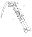
Anhand der Figur 1 wird der prinzipielle Aufbau der Kupplungsvorrichtung näher erläutert. Derartige Kupplungsvorrichtungen kommen bei Schienenfahrzeugen zum Einsatz, wobei sich die gezeigte Kupplungsvorrichtung insbesondere für den Einsatz an Strassenbahnen eignet. Da der grundsätzliche Aufbau von derartigen Kupplungsvorrichtungen bekannt ist, sind viele Bereiche der Kupplungsvorrichtung nur schematisch dargestellt. Im wesentlichen wird nachfolgend deshalb nur auf die erfindungsgemäss relevanten oder die für das Verständnis der Funktionsweise der Kupplungsvorrichtung wichtigen Bauteile eingegangen.The basic structure of the coupling device is explained in more detail with reference to FIG. Coupling devices of this type are used in rail vehicles Use, the coupling device shown being particularly suitable for use suitable for trams. Because the basic structure of such coupling devices is known, many areas of the coupling device are only schematic shown. Essentially, therefore, only those according to the invention are described below relevant or for understanding the operation of the coupling device important components.
Die Kupplungsvorrichtung weist einen durch zwei Gelenkarme gebildeten Tragarm 1
auf, wobei der dem Schienenfahrzeug zugewandte hintere Gelenkarm das Bezugszeichen
2 trägt und der vordere, dem Schienenfahrzeug abgewandte Gelenkarm mit
dem Bezugszeichen 3 versehen ist. Der hintere Gelenkarm 2 ist über ein Lager 7
drehbar am Schienenfahrzeug angeordnet, währenddem die beiden Gelenkarme 2, 3
über ein Knickgelenk 8 miteinander verbunden sind. Am vorderen Gelenkarm 3 ist
der eigentliche Kupplungskopf 39 angeordnet.The coupling device has a
Um die beiden Gelenkarme 2, 3 in der hier gezeigten gestreckten Stellung gegenseitig
fixieren zu können, ist am hinteren Gelenkarm 2 ein Verriegelungsmechanismus
11 angeordnet, welcher den vorderen Gelenkarm 3 an einem das Knickgelenk 8
fahrzeugseitig überragenden Fortsatz 5 verdrehsicher fixiert. Der Verriegelungsmechanismus
11 weist dazu einen drehbar angeordneten Verriegelungshebel 12 auf,
welcher von einer Feder 13 in der verriegelten Stellung gehalten wird. Zum Verdrehen
des Verriegelungshebels 12 ist diesem mit einem Zugseil 14 verbunden, welches
endseitig mit einem Handgriff 15 zum manuellen Entriegeln des Verriegelungsmechanismus
11 versehen ist.Around the two articulated
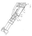
Um den beiden Gelenkarmen 2, 3 beim Einknicken eine bestimmte Bewegungsbahn
vorzugeben und aufzuzwingen, ist eine Führungsanordnung 17 vorgesehen, die ein
aus einem Seil 23 bestehendes Führungsmittel aufweist, das auf der einen Seite am
Schienenfahrzeug und auf der anderen Seite mittels einer Hebelanordnung 18 an
dem das Knickgelenk 8 fahrzeugseitig überragenden Fortsatz 5 des vorderen Gelenkarms
3 angeordnet ist. Diese Hebelanordnung 18 weist eine um eine Achse 21
drehbare Lasche 19 auf, die von einer Feder 20 gegen einen Anschlag 22 gezogen
wird. An dieser Lasche 19 ist das Führungsseil 23 befestigt, das auf der anderen
Seite mittels eines Arms 24 am Schienenfahrzeug befestigt ist. Der Befestigungspunkt
des Führungsseils 23 an der Lasche 19 ist mit 19a bezeichnet, währenddem
der Befestigungspunkt des Führungsseils 23 am Arm 24 das Bezugszeichen 24a
trägt. Die Führungsanordnung 17 ist so dimensioniert, dass die Kraftlinie -in der dargestellten
Wirkstellung der Kupplungsvorrichtung- zwischen den zwei Befestigungspunkten
19a, 24a des Führungsseils 23 ausserhalb der Drehachse 21 der drehbaren
Lasche 19, d.h. auf der dem Tragarm 1 abgewandten Seite, verläuft. Die Funktion
und die Wirkungsweise der Führungsanordnung 17 wird anschliessend noch näher
erläutert.A certain movement path around the two articulated
Um den eingeknickten Tragarm 1 in der Ruhestellung fixieren zu können, ist eine am
Schienenfahrzeug angeordnete Halterung 34 vorgesehen, deren Funktionsweise anschliessend
ebenfalls noch näher erläutert wird. Schliesslich ist im Bereich der Anlenkung
des hinteren Gelenkarms 2 eine Federanordnung 26 vorgesehen, welche
den Tragarm 1 in der hier gezeigten Wirkstellung zu halten bestrebt ist. Die Federanordnung
26 weist nebst der eigentlichen Feder 27 zwei Rollenhebel 28, 29 auf,
welche mit am hinteren Gelenkarm 2 angeordneten Nocken 30, 31 zusammenzuarbeiten
bestimmt sind. Die Federanordnung 26 ist im vorliegenden Fall so ausgelegt,
dass sie die Kupplungsvorrichtung in der funktionsbereiten Wirkstellung gegenüber
der Längsmittelachse des Schienenfahrzeugs um ca. 2.5° auslenkt, so dass sich der
Kupplungskopf 39 beim Einkuppeln selbsttätig entlang seiner kopfseitigen Abschrägung,
relativ zum gegenüberliegenden Kupplungskopf, in die Endkuppelstellung bewegen
kann.In order to fix the buckled
Fig. 2 zeigt die Kupplungsvorrichtung beim seitlichen Auslenken in der einen Richtung
und Fig. 3 in der anderen Richtung. In der gestreckten und verriegelten Stellung
kann der Tragarm 1 entgegen der Kraft der Feder 27 seitlich verschwenkt werden.
Wenn die Kupplungsvorrichtung, vom Schienenfahrzeug aus gesehen, nach links
verschwenkt wird (Fig. 2), so verringert sich die Distanz zwischen den zwei Befestigungspunkten
19a, 24a des Führungsseils 23, was zu einem Durchhängen des Führungsseils
19 führt, ohne dass dieses die Bewegung des Tragarms 1 beeinflussen
würde. Wenn die Kupplungsvorrichtung, vom Schienenfahrzeug aus gesehen, nach
rechts verschwenkt wird (Fig. 3), so vergrössert sich die Distanz zwischen den zwei
Befestigungspunkten 19a, 24a des Führungsseils 23, so dass sich dieses spannt. Da
die Kraftlinie 25 zwischen den zwei Befestigungspunkten 19a, 24a des Führungsseils
23 ausserhalb der Drehachse 21, d.h. auf der dem Tragarm 1 abgewandten Seite,
der drehbaren Lasche 19 verläuft, wird die Lasche 19 vom Führungsseil 23 um die
Drehachse 21 gedreht, so dass auch in diesem Fall die Bewegung des Tragarms 1
nicht nennenswert beeinflusst wird. Die Feder 20 stellt dabei sicher, dass die Lasche
19 beim Zurückschwenken des Tragarms 1 wieder in die Ausgangslage zurückgedreht
wird und sich am Anschlag 22 anlegt. Das bedeutet somit, dass die Kupplungsvorrichtung
bei gestrecktem und arretiertem Tragarm 1 seitlich in beiden Richtungen
ausgelenkt werden kann, ohne dass die Führungsanordnung 17 aktiviert wird.Fig. 2 shows the coupling device during lateral deflection in one direction
and Fig. 3 in the other direction. In the stretched and locked position
the
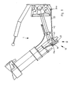
Anhand der Figuren 4 bis 7 soll die Wirkungsweise der Führungsanordnung 17 beim
Einknicken der beiden Gelenkarme 2, 3 erläutert werden. Um den Tragarm 1 einknicken
und die Kupplungsvorrichtung in einen kompakten, zurückgezogenen Zustand
überführen zu können, muss zuerst der Verriegelungsmechanismus 11 entriegelt
werden. Durch Ziehen am Handgriff 15 wird der Verriegelungshebel 12 über das
Zugseil 14 entgegen der Kraft der Feder 13 verdreht, wie dies in der Figur 4 gezeigt
ist. Nun kann der Kupplungskopf 39 manuell in Richtung des Pfeiles P verschwenkt
werden (Fig. 5). Durch das Verschwenken des Kupplungskopfs 39 wird der Fortsatz
5 und mit ihm die daran angeordnete Hebelanordnung 18 um den Drehpunkt 9 des
Knickgelenks 8 herum verdreht, dass die Kraftlinie zwischen den zwei Befestigungspunkten
19a, 24a des Führungsseils 23 nach innen auf die dem Tragarm 1 zugewandte
Seite der Drehachse 21 wandert. Die Länge des Führungsseils 23 ist dabei
so dimensioniert, dass dieses erst dann soweit gespannt ist, dass es nennenswerte
Kräfte übertragen kann, wenn die Kraftlinie 25 zwischen den zwei Befestigungspunkten
19a, 24a des Führungsseils 23 innerhalb der Drehachse 21 der Lasche 19
verläuft. Nachdem die genannte Kraftlinie 25 innerhalb der Drehachse 21 der Lasche
19 verläuft, spannt sich das Führungsseil 23 straff, so dass die Lasche 19 vom Führungsseil
23 in Richtung des Anschlags 22 gezogen wird, was dazu führt, dass die
Lasche 19 in dieser Wirkstellung verharrt und das Führungsseil 23 Kräfte übertragen
kann. Wenn also das Führungsseil 23 gespannt ist und der Kupplungskopf 39 weiter
verschwenkt wird, so wird dem hinteren Gelenkarm 2 eine Schwenkbewegung nach
links aufgezwungen, da sich der Abstand zwischen der Stirnseite des Schienenfahrzeugs
und dem Befestigungspunkt 19a des Führungsseils 23 an der Lasche 19,
durch das gestreckte Führungsseil 23, nicht mehr vergrössem kann.Based on Figures 4 to 7, the operation of the
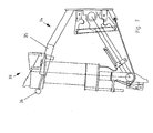
Fig. 6 zeigt eine Zwischenphase beim Einknicken des Tragarms 1. Aus dieser Darstellung
ist ersichtlich, wie der hintere Gelenkarm 2 durch das gestreckte Führungsseil
23 nach links in Richtung des Pfeiles P1 ausgelenkt wird, wenn der vordere Gelenkarm
3 nach rechts verschwenkt wird. 6 shows an intermediate phase when the
Fig. 7 zeigt die Kupplungsvorrichtung in vollständig eingeknicktem Zustand. Der
Kupplungskopf 39 ist dabei in der Halterung 34 aufgenommen und darin fixiert. Die
Halterung 34 weist einen verschwenkbaren Auslegerarm 35 auf, der den Kupplungskopf
39 unterstützt und durch eine Schwenkbewegung, in eine verriegelte Fixierstellung
überführt. Beim Verschwenken des Auslegerarms 35 wird der Kupplungskopf 39
angehoben, so dass die gesamte Kupplungsvorrichtung in eine horizontale Lage gebracht
wird. Dies ist deshalb wichtig, da verschiedene Elemente wie beispielsweise
das Knickgelenk 8 Spiel haben und/oder mit nachgiebigen Dämpfungselementen
versehen sind, so dass der eingeknickte Tragarm 1 die Tendenz hat, etwas nach
unten zu hängen. Zum Entriegeln der Halterung 34 ist ein Hebel 36 vorgesehen, der
manuell betätigbar ist.Fig. 7 shows the coupling device in a fully buckled state. The
In der Fig. 8 ist die Kupplungsvorrichtung mit einer alternativen Ausbildung einer Führungsanordnung
17 dargestellt. In diesem Ausführungsbeispiel ist anstelle eines Führungsseils
eine Führungsstange 42 vorgesehen. Zum Fixieren der Führungsstange
42 am Tragarm 1 ist die Hebelanordnung 18 mit einem bogenförmigen Element 43
versehen, das drehbar an der Lasche 19 abgestützt ist. Die Führungsstange 42 ist in
einer Aufnahme am bogenförmigen Element 43 geführt und mit einem Anschlag
(nicht dargestellt) versehen, welcher bewirkt, dass sich die Führungsstange 42 beim
Verschwenken des Tragarms 1 nach links frei durch die Aufnahme hindurchbewegen
kann -aufgrund der Verkürzung der Distanz zwischen dem Befestigungspunkt des
Führungssmittels am Schienenfahrzeug und der Aufnahme- und daher inaktiv ist,
währenddem sich der Anschlag der Führungsstange 42 beim Verschwenken des
Tragarms 1 nach rechts an der Aufnahme anlegt und die Lasche 19 in der vorgängig
beschriebenen Weise entgegen der Federvorspannung um die Drehachse 21 verdreht,
so dass der Tragarm 1 ohne nennwenswerte Beeinflussung nach rechts verschwenkt
werden kann. Beim Einknicken des Tragarms 1 wandert die Kraftlinie 25
zwischen den zwei Befestigungspunkten 19a, 24a der Führungsstange 42 nach innen
auf die dem Tragarm 1 zugewandten Seite, wodurch wiederum bewirkt wird,
dass die Führungsstange 42 den beiden Gelenkarmen 2, 3 eine Schwenkbahn aufzwingt.8 is the coupling device with an alternative embodiment of a
Fig. 9 zeigt eine Draufsicht auf die Kupplungsvorrichtung in der Wirkstellung W und in
der Ruhestellung R, in welcher die Kupplungsvorrichtung in der Halterung 34 aufgenommen
ist. Aus dieser Darstellung sind zudem schematisch die Konturen des
Schienenfahrzeugs S ersichtlich. Ebenso ist die Bewegungsbahn B des Kupplungskopfs
39 beim Überführen von der Wirkstellung W in die Ruhestellung R ersichtlich. Fig. 9 shows a plan view of the coupling device in the active position W and in
the rest position R, in which the coupling device is received in the
Aufgrund der Bewegungsbahn B ist ersichtlich, dass die Kupplungsvorrichtung während des Einknickens viel weniger Platz benötigt als dies bei einem herkömmlichen Knickmechanismus der Fall wäre. Zudem beansprucht die Kupplungsvorrichtung auch im vollständig eingeknickten Zustand (Ruhestellung R) sehr wenig Platz im Vergleich zu konventionellen Kupplungsvorrichtungen.Due to the movement path B it can be seen that the coupling device during of buckling takes up much less space than a conventional one Would be the case. In addition, the coupling device claims even in the fully folded state (rest position R) very little space in the Compared to conventional coupling devices.
Durch verschiedene Massnahmen, namentlich durch die Ausgestaltung und den Befestigungsort der Hebelanordnung sowie durch den Befestigungsort des Führungsmittels am Schienenfahrzeug kann der von der Kupplungsvorrichtung zum Einknicken benötigte Freiraum variiert werden bzw. die Kupplungsvorrichtung kann an die Gegebenheiten des Schienenfahrzeugs angepasst werden. Ausserdem kann die Schwenkbahn so gewählt werden, dass der Kupplungskopf einen vorgegebenen seitlichen Bereich nicht verlässt, indem der Kupplungskopf beim Einschwenken beispielsweise nie über die seitliche Kontur des Schienenfahrzeugs vorzustehen kommt. Ausserdem kann, je nach seitlichem Auslenken des hinteren Gelenkarms, die Ruhestellung der Kupplungsvorrichtung bzw. deren Platzbedarf variiert werden.Through various measures, in particular through the design and the Fastening location of the lever arrangement and by the fastening location of the guide means on the rail vehicle, the coupling device can buckle required space can be varied or the coupling device can the conditions of the rail vehicle are adjusted. In addition, the Swivel path can be selected so that the coupling head a predetermined does not leave the lateral area, for example by the coupling head when swiveling never protrudes beyond the lateral contour of the rail vehicle. In addition, depending on the lateral deflection of the rear articulated arm, the rest position the coupling device or its space requirements can be varied.
Nebst dem hier beschriebenen Ausführungsbeispiel einer Kupplungsvorrichtung können im Rahmen des in den Patentansprüchen definierten Schutzumfanges natürlich auch andersartig gestaltete Kupplungsvorrichtungen vorgesehen werden. Anstelle eines manuell zu betätigenden Einknickmechanismus könnte dieser auch elektrisch, pneumatisch oder hydraulisch angetrieben werden.In addition to the exemplary embodiment of a coupling device described here can of course within the scope of protection defined in the claims also differently designed coupling devices can be provided. Instead of a manually operated folding mechanism could also be electrical, be driven pneumatically or hydraulically.
Claims (9)
- Coupling device for rail vehicles, with a rear articulated arm (2) articulated on the vehicle side and with a front articulated arm (3) which is connected to the rear articulated arm (2) via a buckling joint (8) which carries a coupling head (39), characterized in that the coupling device is provided with a guide arrangement (17) which, during the buckling of the front articulated arm (3), imparts to the rear articulated arm (2) a pivoting movement opposite to the direction of movement of the front articulated arm (3).
- Coupling device according to Claim 1, characterized in that the guide arrangement (17) comprises a guide means (23) which is fixed on the vehicle side and, during buckling, predetermines the pivoting path of the two articulated arms (2, 3) and which is fixed directly or indirectly to the front articulated arm (3).
- Coupling device according to Claim 2, characterized in that the guide means (23) forms an angle with the longitudinal mid-axis (40) of the extended carrying arm (1) of the coupling device when the latter is in the active position ready for functioning.
- Coupling device according to Claim 2 or 3, characterised in that the guide means (23) is connected to the front articulated arm (3) by means of a lever arraagemeat (18), the lever arrangement (18) being pivotable between an active and an inactive position in such a way that the guide means (23) is inactive during pivoting movements of the extended carrying arm (1). whereas it is active during the buckling of the front articulated arm (3).
- Coupliag device according to Claim 4, characterized in that the front articulated arm (3) has an extension (5) which projects beyond the buckling joint (8) on the vehicle side when the carrying arm (1) is in the extended state and to which the lever arrangement (18) is fixed.
- Coupling device according to Claim 5, characterized in that a locking mechanism (11) for fixing the front articulated arm (3) to the rear articulated arm (2) is provided, the locking mechanism (11) being arranged on the rear articulated arm (2) and being intended for fixing the front articulated arm (3) to the extension (5) of the latter.
- Coupling device according to, one of the preceding claims, characterized in that a spring arrangement (26) endeavouring to hold the extended carrying arm (1) in the middle position is provided, the extended carrying arm (1) being pivotable counter to the spring force of the spring arrangement (26), and the spring arrangement (26), together with the guide means (23), imparting the pivoting path to the two articulated arms (2, 3) during buckling.
- Coupling device according to Claims 4 to 7, characterized in that the lever arrangement (18) comprises a rotatably mounted strap (19), to which the guide means (23) is fixed, there being provided at least one spring (20) endeavouring to hold the strap (19) in an active position, and the line of force (25) between the vehicle-side fixing point (24a) of the guide means (23) and the carrying-arm-side fixing point (19a) of the guide means (23) running on the outside. facing away from the carrying arm (1), of the axis of rotation (21) of the strap (19) when the carrying arm (1) is in the extended state, so that, during a pivoting movement of the extended carrying arm (1), the strap (19) can be rotated by the guide means (23) into an inactive position counter to the spring prestress.
- Coupling device according to Claim 8, characterized in that the guide arrangement (17) is designed in such a way that, during the buckling of the carrying arm (1), the said line of force (25) is displaced onto that side of the axis of rotation (21) of the rotatable strap (19) which faces the carrying arm (1), before the guide means (23) is active, so that the active guide means (23) endeavours to hold the rotatable strap (19) in the active position and guiding forces can be transmitted to the carrying arm (1) by the guide means (23).
Applications Claiming Priority (2)
| Application Number | Priority Date | Filing Date | Title |
|---|---|---|---|
| DE10010062A DE10010062C2 (en) | 2000-03-02 | 2000-03-02 | Coupling device for rail vehicles |
| DE10010062 | 2000-03-02 |
Publications (2)
| Publication Number | Publication Date |
|---|---|
| EP1129920A1 EP1129920A1 (en) | 2001-09-05 |
| EP1129920B1 true EP1129920B1 (en) | 2003-04-23 |
Family
ID=7633166
Family Applications (1)
| Application Number | Title | Priority Date | Filing Date |
|---|---|---|---|
| EP01810122A Expired - Lifetime EP1129920B1 (en) | 2000-03-02 | 2001-02-07 | Foldable coupling bar for rail vehicles |
Country Status (4)
| Country | Link |
|---|---|
| EP (1) | EP1129920B1 (en) |
| AT (1) | ATE238187T1 (en) |
| DE (2) | DE10010062C2 (en) |
| ES (1) | ES2197138T3 (en) |
Families Citing this family (9)
| Publication number | Priority date | Publication date | Assignee | Title |
|---|---|---|---|---|
| DE10355640B3 (en) | 2003-11-28 | 2004-11-04 | Voith Turbo Scharfenberg Gmbh & Co. Kg | Central buffer coupling for rail vehicles comprises a coupling head and a coupling shaft having a section formed by a first partial piece and a second partial piece connected together by an overload protection |
| DK1619101T3 (en) * | 2004-07-20 | 2007-05-14 | Voith Turbo Scharfenberg Gmbh | Operating and traction coupling |
| DE102016210685B3 (en) * | 2016-06-15 | 2017-08-17 | Siemens Aktiengesellschaft | Clutch bracket for a rail vehicle |
| CN106274960B (en) * | 2016-08-31 | 2018-02-06 | 中车青岛四方车辆研究所有限公司 | The locking device of collapsible hitch, collapsible hitch and its locking means |
| CN106985877B (en) * | 2016-12-29 | 2018-03-27 | 比亚迪股份有限公司 | Draft gear assemblies and there is its sit-astride track train |
| CN109455192B (en) * | 2017-09-06 | 2019-08-27 | 常州中车铁马科技实业有限公司 | Folding type coupler locking mechanism and working method thereof |
| CN110422194B (en) * | 2019-09-09 | 2024-03-08 | 中车青岛四方车辆研究所有限公司 | Folding car coupler and vehicle |
| EP3992054B1 (en) * | 2019-09-09 | 2023-07-19 | Crrc Qingdao Sifang Rolling Stock Research Institute Co., Ltd. | Foldable vehicular coupler and vehicle |
| US20230234624A1 (en) * | 2020-07-09 | 2023-07-27 | Dellner Couplers Ab | Device for deflection of a coupler of a train vehicle, coupler of a train, car of a multi-car vehicle and method for coupling a first car of a multi-car vehicle to a second car of a multi-car vehicle |
Family Cites Families (4)
| Publication number | Priority date | Publication date | Assignee | Title |
|---|---|---|---|---|
| US2577495A (en) * | 1947-10-16 | 1951-12-04 | Buckeye Steel Castings Co | Locomotive pilot and coupler therefor |
| DE4006811A1 (en) * | 1990-03-05 | 1991-09-12 | Bergische Stahlindustrie | Central buffer coupling between rail vehicles - has middle part of bumper bar coupled to hinging head |
| DE4328811C1 (en) * | 1993-08-27 | 1994-10-27 | Scharfenbergkupplung Gmbh | Centre buffer coupling for rail vehicles |
| DE19526504C1 (en) * | 1995-07-20 | 1996-07-25 | Bergische Stahlindustrie | Middle buffer coupling for rail vehicles |
-
2000
- 2000-03-02 DE DE10010062A patent/DE10010062C2/en not_active Expired - Fee Related
-
2001
- 2001-02-07 EP EP01810122A patent/EP1129920B1/en not_active Expired - Lifetime
- 2001-02-07 AT AT01810122T patent/ATE238187T1/en not_active IP Right Cessation
- 2001-02-07 ES ES01810122T patent/ES2197138T3/en not_active Expired - Lifetime
- 2001-02-07 DE DE50100182T patent/DE50100182D1/en not_active Expired - Lifetime
Also Published As
| Publication number | Publication date |
|---|---|
| DE10010062A1 (en) | 2001-09-13 |
| DE50100182D1 (en) | 2003-05-28 |
| DE10010062C2 (en) | 2002-01-31 |
| ATE238187T1 (en) | 2003-05-15 |
| ES2197138T3 (en) | 2004-01-01 |
| EP1129920A1 (en) | 2001-09-05 |
Similar Documents
| Publication | Publication Date | Title |
|---|---|---|
| DE4118683C1 (en) | ||
| EP1621386B1 (en) | Wind stop device | |
| DE102006013847B4 (en) | Automotive seat | |
| EP1884410B1 (en) | Rear load carrier | |
| DE10307149A1 (en) | Folding vehicle seat | |
| EP1129920B1 (en) | Foldable coupling bar for rail vehicles | |
| EP4299414A1 (en) | Steering column for a motor vehicle | |
| DE19961617A1 (en) | Headrest on seat back in motor vehicle has support component with support frame inside headrest cushion and extending in front of cushion support, and support frame can pivot on cushion support by swivel arms | |
| DE69509481T2 (en) | Device for anchoring a motor vehicle seat belt end | |
| DE69427033T2 (en) | DEVICE FOR EXTENDING AND EXHAUSTING A HORIZONTAL BOOM | |
| DE102006043428A1 (en) | Drive for adjusting trailer coupling between resting and operating positions in e.g. passenger car, has traction cables that are guided through respective control mechanisms that are driven by common rotating drive unit | |
| EP1528991B1 (en) | Holding device for containers, such as beverage containers, particularly for mounting in vehicles | |
| DE102020113606B4 (en) | Front hood hinge and front hood hinge construction | |
| DE4427518C1 (en) | Superstructure body for lorries and trailers | |
| DE4402978C2 (en) | Rear seat back for motor vehicles | |
| EP1129921B1 (en) | Coupling device for railway vehicles | |
| EP0876937A1 (en) | Crash lock | |
| EP3710334B1 (en) | Steering column for a motor vehicle | |
| DE102019202575B3 (en) | Mast attachment tip for a mobile crane and mobile crane | |
| DE19512384C2 (en) | Middle buffer coupling for rail vehicles | |
| DE69718955T2 (en) | awning | |
| DE102004030996A1 (en) | Vehicle e.g. passenger car, has safety unit arranged between chassis and front hood in such manner that front hood is held back in its exposed position before windshield of vehicle against main driving direction of vehicle | |
| DE102019133553A1 (en) | Holding bracket device for a transport trailer or for an animal transporter | |
| DE102015109504B4 (en) | Device for disassembling a steering knuckle | |
| DE1455221C3 (en) | Device for actuating automatic couplings on rail vehicles |
Legal Events
| Date | Code | Title | Description |
|---|---|---|---|
| PUAI | Public reference made under article 153(3) epc to a published international application that has entered the european phase |
Free format text: ORIGINAL CODE: 0009012 |
|
| AK | Designated contracting states |
Kind code of ref document: A1 Designated state(s): AT BE CH CY DE DK ES FI FR GB GR IE IT LI LU MC NL PT SE TR |
|
| AX | Request for extension of the european patent |
Free format text: AL;LT;LV;MK;RO;SI |
|
| 17P | Request for examination filed |
Effective date: 20011011 |
|
| AKX | Designation fees paid |
Free format text: AT BE CH CY DE DK ES FI FR GB GR IE IT LI LU MC NL PT SE TR |
|
| GRAH | Despatch of communication of intention to grant a patent |
Free format text: ORIGINAL CODE: EPIDOS IGRA |
|
| GRAH | Despatch of communication of intention to grant a patent |
Free format text: ORIGINAL CODE: EPIDOS IGRA |
|
| GRAA | (expected) grant |
Free format text: ORIGINAL CODE: 0009210 |
|
| AK | Designated contracting states |
Designated state(s): AT BE CH CY DE DK ES FI FR GB GR IE IT LI LU MC NL PT SE TR |
|
| PG25 | Lapsed in a contracting state [announced via postgrant information from national office to epo] |
Ref country code: IE Free format text: LAPSE BECAUSE OF NON-PAYMENT OF DUE FEES Effective date: 20030423 Ref country code: GB Free format text: LAPSE BECAUSE OF FAILURE TO SUBMIT A TRANSLATION OF THE DESCRIPTION OR TO PAY THE FEE WITHIN THE PRESCRIBED TIME-LIMIT Effective date: 20030423 Ref country code: CY Free format text: LAPSE BECAUSE OF FAILURE TO SUBMIT A TRANSLATION OF THE DESCRIPTION OR TO PAY THE FEE WITHIN THE PRESCRIBED TIME-LIMIT Effective date: 20030423 |
|
| REG | Reference to a national code |
Ref country code: GB Ref legal event code: FG4D Free format text: NOT ENGLISH |
|
| REG | Reference to a national code |
Ref country code: CH Ref legal event code: EP |
|
| REG | Reference to a national code |
Ref country code: CH Ref legal event code: NV Representative=s name: ROTTMANN, ZIMMERMANN + PARTNER AG |
|
| REF | Corresponds to: |
Ref document number: 50100182 Country of ref document: DE Date of ref document: 20030528 Kind code of ref document: P |
|
| REG | Reference to a national code |
Ref country code: IE Ref legal event code: FG4D Free format text: GERMAN |
|
| REG | Reference to a national code |
Ref country code: GR Ref legal event code: EP Ref document number: 20030401646 Country of ref document: GR |
|
| PG25 | Lapsed in a contracting state [announced via postgrant information from national office to epo] |
Ref country code: DK Free format text: LAPSE BECAUSE OF FAILURE TO SUBMIT A TRANSLATION OF THE DESCRIPTION OR TO PAY THE FEE WITHIN THE PRESCRIBED TIME-LIMIT Effective date: 20030723 Ref country code: PT Free format text: LAPSE BECAUSE OF FAILURE TO SUBMIT A TRANSLATION OF THE DESCRIPTION OR TO PAY THE FEE WITHIN THE PRESCRIBED TIME-LIMIT Effective date: 20030723 |
|
| REG | Reference to a national code |
Ref country code: SE Ref legal event code: TRGR |
|
| GBV | Gb: ep patent (uk) treated as always having been void in accordance with gb section 77(7)/1977 [no translation filed] |
Effective date: 20030423 |
|
| REG | Reference to a national code |
Ref country code: IE Ref legal event code: FD4D Ref document number: 1129920E Country of ref document: IE |
|
| ET | Fr: translation filed | ||
| REG | Reference to a national code |
Ref country code: ES Ref legal event code: FG2A Ref document number: 2197138 Country of ref document: ES Kind code of ref document: T3 |
|
| PG25 | Lapsed in a contracting state [announced via postgrant information from national office to epo] |
Ref country code: LU Free format text: LAPSE BECAUSE OF NON-PAYMENT OF DUE FEES Effective date: 20040207 |
|
| PGFP | Annual fee paid to national office [announced via postgrant information from national office to epo] |
Ref country code: TR Payment date: 20040216 Year of fee payment: 4 |
|
| PLBE | No opposition filed within time limit |
Free format text: ORIGINAL CODE: 0009261 |
|
| STAA | Information on the status of an ep patent application or granted ep patent |
Free format text: STATUS: NO OPPOSITION FILED WITHIN TIME LIMIT |
|
| PG25 | Lapsed in a contracting state [announced via postgrant information from national office to epo] |
Ref country code: MC Free format text: LAPSE BECAUSE OF NON-PAYMENT OF DUE FEES Effective date: 20040228 |
|
| 26N | No opposition filed |
Effective date: 20040126 |
|
| PGFP | Annual fee paid to national office [announced via postgrant information from national office to epo] |
Ref country code: NL Payment date: 20050119 Year of fee payment: 5 |
|
| PGFP | Annual fee paid to national office [announced via postgrant information from national office to epo] |
Ref country code: GR Payment date: 20050126 Year of fee payment: 5 |
|
| PGFP | Annual fee paid to national office [announced via postgrant information from national office to epo] |
Ref country code: IT Payment date: 20060228 Year of fee payment: 6 |
|
| PGFP | Annual fee paid to national office [announced via postgrant information from national office to epo] |
Ref country code: AT Payment date: 20060309 Year of fee payment: 6 |
|
| PGFP | Annual fee paid to national office [announced via postgrant information from national office to epo] |
Ref country code: FI Payment date: 20060315 Year of fee payment: 6 |
|
| PGFP | Annual fee paid to national office [announced via postgrant information from national office to epo] |
Ref country code: ES Payment date: 20060328 Year of fee payment: 6 |
|
| PGFP | Annual fee paid to national office [announced via postgrant information from national office to epo] |
Ref country code: BE Payment date: 20060331 Year of fee payment: 6 |
|
| PG25 | Lapsed in a contracting state [announced via postgrant information from national office to epo] |
Ref country code: NL Free format text: LAPSE BECAUSE OF NON-PAYMENT OF DUE FEES Effective date: 20060901 |
|
| NLV4 | Nl: lapsed or anulled due to non-payment of the annual fee |
Effective date: 20060901 |
|
| PG25 | Lapsed in a contracting state [announced via postgrant information from national office to epo] |
Ref country code: FI Free format text: LAPSE BECAUSE OF NON-PAYMENT OF DUE FEES Effective date: 20070207 |
|
| PG25 | Lapsed in a contracting state [announced via postgrant information from national office to epo] |
Ref country code: AT Free format text: LAPSE BECAUSE OF NON-PAYMENT OF DUE FEES Effective date: 20070207 |
|
| BERE | Be: lapsed |
Owner name: *SCHWAB VERKEHRSTECHNIK A.G. Effective date: 20070228 |
|
| PG25 | Lapsed in a contracting state [announced via postgrant information from national office to epo] |
Ref country code: BE Free format text: LAPSE BECAUSE OF NON-PAYMENT OF DUE FEES Effective date: 20070228 |
|
| REG | Reference to a national code |
Ref country code: ES Ref legal event code: FD2A Effective date: 20070208 |
|
| PG25 | Lapsed in a contracting state [announced via postgrant information from national office to epo] |
Ref country code: ES Free format text: LAPSE BECAUSE OF NON-PAYMENT OF DUE FEES Effective date: 20070208 |
|
| PG25 | Lapsed in a contracting state [announced via postgrant information from national office to epo] |
Ref country code: GR Free format text: LAPSE BECAUSE OF NON-PAYMENT OF DUE FEES Effective date: 20060904 |
|
| PG25 | Lapsed in a contracting state [announced via postgrant information from national office to epo] |
Ref country code: TR Free format text: LAPSE BECAUSE OF FAILURE TO SUBMIT A TRANSLATION OF THE DESCRIPTION OR TO PAY THE FEE WITHIN THE PRESCRIBED TIME-LIMIT Effective date: 20030423 Ref country code: IT Free format text: LAPSE BECAUSE OF NON-PAYMENT OF DUE FEES Effective date: 20070207 |
|
| REG | Reference to a national code |
Ref country code: CH Ref legal event code: NV Representative=s name: LUCHS & PARTNER PATENTANWAELTE |
|
| REG | Reference to a national code |
Ref country code: FR Ref legal event code: PLFP Year of fee payment: 16 |
|
| REG | Reference to a national code |
Ref country code: FR Ref legal event code: PLFP Year of fee payment: 17 |
|
| PGFP | Annual fee paid to national office [announced via postgrant information from national office to epo] |
Ref country code: FR Payment date: 20170217 Year of fee payment: 17 Ref country code: SE Payment date: 20170216 Year of fee payment: 17 Ref country code: DE Payment date: 20170217 Year of fee payment: 17 Ref country code: CH Payment date: 20170228 Year of fee payment: 17 |
|
| REG | Reference to a national code |
Ref country code: DE Ref legal event code: R119 Ref document number: 50100182 Country of ref document: DE |
|
| REG | Reference to a national code |
Ref country code: CH Ref legal event code: PL |
|
| REG | Reference to a national code |
Ref country code: SE Ref legal event code: EUG |
|
| PG25 | Lapsed in a contracting state [announced via postgrant information from national office to epo] |
Ref country code: SE Free format text: LAPSE BECAUSE OF NON-PAYMENT OF DUE FEES Effective date: 20180208 |
|
| PG25 | Lapsed in a contracting state [announced via postgrant information from national office to epo] |
Ref country code: CH Free format text: LAPSE BECAUSE OF NON-PAYMENT OF DUE FEES Effective date: 20180228 Ref country code: LI Free format text: LAPSE BECAUSE OF NON-PAYMENT OF DUE FEES Effective date: 20180228 |
|
| REG | Reference to a national code |
Ref country code: FR Ref legal event code: ST Effective date: 20181031 |
|
| PG25 | Lapsed in a contracting state [announced via postgrant information from national office to epo] |
Ref country code: DE Free format text: LAPSE BECAUSE OF NON-PAYMENT OF DUE FEES Effective date: 20180901 |
|
| PG25 | Lapsed in a contracting state [announced via postgrant information from national office to epo] |
Ref country code: FR Free format text: LAPSE BECAUSE OF NON-PAYMENT OF DUE FEES Effective date: 20180228 |