EP1129873B1 - Porte de véhicule et procédé d'assemblage de la porte de véhicule - Google Patents
Porte de véhicule et procédé d'assemblage de la porte de véhicule Download PDFInfo
- Publication number
- EP1129873B1 EP1129873B1 EP01103360A EP01103360A EP1129873B1 EP 1129873 B1 EP1129873 B1 EP 1129873B1 EP 01103360 A EP01103360 A EP 01103360A EP 01103360 A EP01103360 A EP 01103360A EP 1129873 B1 EP1129873 B1 EP 1129873B1
- Authority
- EP
- European Patent Office
- Prior art keywords
- panel
- plastic
- door
- mounting panel
- structural part
- Prior art date
- Legal status (The legal status is an assumption and is not a legal conclusion. Google has not performed a legal analysis and makes no representation as to the accuracy of the status listed.)
- Expired - Lifetime
Links
Images


Classifications
-
- B—PERFORMING OPERATIONS; TRANSPORTING
- B60—VEHICLES IN GENERAL
- B60J—WINDOWS, WINDSCREENS, NON-FIXED ROOFS, DOORS, OR SIMILAR DEVICES FOR VEHICLES; REMOVABLE EXTERNAL PROTECTIVE COVERINGS SPECIALLY ADAPTED FOR VEHICLES
- B60J5/00—Doors
- B60J5/04—Doors arranged at the vehicle sides
- B60J5/0412—Lower door structure
- B60J5/0416—Assembly panels to be installed in doors as a module with components, e.g. lock or window lifter, attached thereto
-
- B—PERFORMING OPERATIONS; TRANSPORTING
- B60—VEHICLES IN GENERAL
- B60J—WINDOWS, WINDSCREENS, NON-FIXED ROOFS, DOORS, OR SIMILAR DEVICES FOR VEHICLES; REMOVABLE EXTERNAL PROTECTIVE COVERINGS SPECIALLY ADAPTED FOR VEHICLES
- B60J5/00—Doors
- B60J5/04—Doors arranged at the vehicle sides
- B60J5/042—Reinforcement elements
- B60J5/0422—Elongated type elements, e.g. beams, cables, belts or wires
- B60J5/0423—Elongated type elements, e.g. beams, cables, belts or wires characterised by position in the lower door structure
- B60J5/0425—Elongated type elements, e.g. beams, cables, belts or wires characterised by position in the lower door structure the elements being arranged essentially horizontal in the centre of the lower door structure
-
- B—PERFORMING OPERATIONS; TRANSPORTING
- B60—VEHICLES IN GENERAL
- B60J—WINDOWS, WINDSCREENS, NON-FIXED ROOFS, DOORS, OR SIMILAR DEVICES FOR VEHICLES; REMOVABLE EXTERNAL PROTECTIVE COVERINGS SPECIALLY ADAPTED FOR VEHICLES
- B60J5/00—Doors
- B60J5/04—Doors arranged at the vehicle sides
- B60J5/042—Reinforcement elements
- B60J5/0451—Block or short strip-type elements
-
- E—FIXED CONSTRUCTIONS
- E05—LOCKS; KEYS; WINDOW OR DOOR FITTINGS; SAFES
- E05Y—INDEXING SCHEME RELATING TO HINGES OR OTHER SUSPENSION DEVICES FOR DOORS, WINDOWS OR WINGS AND DEVICES FOR MOVING WINGS INTO OPEN OR CLOSED POSITION, CHECKS FOR WINGS AND WING FITTINGS NOT OTHERWISE PROVIDED FOR, CONCERNED WITH THE FUNCTIONING OF THE WING
- E05Y2201/00—Constructional elements; Accessories therefore
- E05Y2201/60—Suspension or transmission members; Accessories therefore
- E05Y2201/622—Suspension or transmission members elements
- E05Y2201/684—Rails
-
- E—FIXED CONSTRUCTIONS
- E05—LOCKS; KEYS; WINDOW OR DOOR FITTINGS; SAFES
- E05Y—INDEXING SCHEME RELATING TO HINGES OR OTHER SUSPENSION DEVICES FOR DOORS, WINDOWS OR WINGS AND DEVICES FOR MOVING WINGS INTO OPEN OR CLOSED POSITION, CHECKS FOR WINGS AND WING FITTINGS NOT OTHERWISE PROVIDED FOR, CONCERNED WITH THE FUNCTIONING OF THE WING
- E05Y2600/00—Mounting or coupling arrangements for elements provided for in this subclass
- E05Y2600/10—Adjustable or movable
Definitions
- the present invention relates to a lightweight door of a vehicle according to the preamble of claim 1, which is easy to assemble and comprises a decreased number of parts and a method of assembling the door.
- a door of this type is disclosed in US 5906072 A.
- vehicle doors are made up of a door panel assembly comprising a steel inner door panel and a steel outer door panel to which various functional parts and devices, such as a window regulator and a door lock/unlock mechanism, are directly installed.
- various functional parts and devices such as a window regulator and a door lock/unlock mechanism
- plastic panel to which various functional parts and devices are installed.
- the plastic panel is attached to the steel inner door panel such that it closes up an opening of the inner door panel.
- One of the vehicle doors is known from, for example, Japanese Unexamined patent application No. 9-156374.
- the plastic panel is formed by press molding or injection molding.
- one piece panel member is used to form the almost entire part of the inner door panel as disclosed in Japanese Unexamined patent application No.9 - 157374, it is almost inevitable that the inner door panel is large in size.
- a large size of mold is necessary. This needs a large amount of plastic material and results in application of considerably high molding pressure or injection pressure. It is undesirable to use a large size of molding equipment and a large amount of material for simply preparing the one piece plastic panel in light of production efficiency.
- a vehicle door comprising an outer door panel, and an inner door panel formed with an aperture, a mounting panel to which functional devices of the vehicle door and door parts are mounted and which is installed to the inner door panel to close up the aperture of the inner door panel.
- the mounting panel comprises a plastic panel formed in conformity with the aperture of the inner door panel, a plastic structural part appendant to the plastic panel, and a breakable joint connecting the plastic structural part to the plastic panel which are formed as one piece by, for example, injection molding.
- the plastic structural part is separated from the plastic panel by breaking away the joint from the plastic panel during installing work of the mounting panel to the inner door panel.
- the plastic structural part is one of the door parts that are mounted to the mounting panel, such as a cover for covering an opening formed in the plastic panel which provides an access to the inside of the vehicle door for assembling the vehicle door.
- the plastic structural part is mounted to the plastic panel desirably after installation of the plastic panel to the inner door panel
- the inner door panel has a substantial wall section forming part of a side wall of a passenger compartment of the vehicle and the plastic structural part before separation from the plastic panel occupies a location where it overlaps the substantial wall section of the inner door panel when the mounting panel is installed.
- the plastic mounting panel is formed as one piece including a structural part which is separated from the plastic mounting plate and mounted to the plastic mounting panel after having been assembled to the vehicle door.
- This configuration of the plastic mounting panel enables putting a large amount of plastic material and a large size molding apparatus to efficient use, so as to increase the productivity of the mounting panel.
- the plastic mounting panel Owing to the configuration of the plastic mounting panel that the plastic structural part before separation from the plastic panel occupies a location where it overlaps the substantial wall section of the inner door panel when the mounting panel is installed, while the plastic mounting panel is formed so as to have the plastic panel in conformity with the aperture of the inner door panel, the plastic structural part is formed as one of the door parts at a location where the plastic panel is in non-occupation.
- the plastic mounting panel can be configured in the form of substantially rectangular flat plate, so that it is easy to pile up a number of the plastic mounting panels and to convey a stack of the plastic mounting panels safely and reliably, without separating the appendant parts.
- the plastic structural part is formed in a generally rectangular panel by locating the plastic structural part as an appendant part to the plastic panel at the cut-off corner.
- the plastic structural part is one of the door parts that be mounted to the mounting panel, the plastic structural part can be always along with the plastic panel until the plastic panel is installed to the door panel and is separated from the plastic panel immediately before the plastic structural part is intended to be installed to the plastic panel. In consequence, it is not feared that the plastic structural part is missing before assembling such as during conveyance thereof.
- the plastic structural part is formed as a cover for covering an opening formed in the plastic panel which provides an access to the inside of the vehicle door for assembling the vehicle door
- the plastic structural part is always along with the plastic panel until the assembling work is finished, so as to make it reliable to cover the access opening in the plastic panel, thereby completing the vehicle door.
- the plastic structural part is separated and then mounted to the plastic panel during assembling work of the vehicle door or after the plastic panel has been installed to the door panel.
- the plastic structural part is separated and then mounted to the plastic panel after having installed the plastic panel to the door panel.
- the plastic structural part is always along with the plastic panel until the assembling work is finished, so that it is not feared that the plastic structural part is missing before assembling such as during conveyance thereof, which makes it reliable to install the plastic structural part to the plastic panel in order to complete the vehicle door.
- the process eliminates the fear that the plastic structural part is missing and provides reliable installation of the plastic structural part to the plastic panel.
- the present invention is applicable to a rear door and a back door with the same effects.
- the vehicle door is made up of a door panel sub-assembly D comprising a steel inner panel D1, a steel outer panel D2 and a steel window sash D3, a plastic mounting panel P, and a trim unit T which forms a side wall of a passenger compartment.
- the window sash D3, which is shaped such as to have a front part inclined rearward as viewed from the front of the vehicle, receives an window glass W therein.
- the door panel D at its front end is provided upper and lower hinges 1 and 2.
- the inner panel D1 has a generally rectangular aperture 3 formed below a belt line and has a front top comer D1a uncut.
- An upper mounting panel Portion D1b above the belt line and integral with the uncut part D1a provides the inner panel D1 with structural rigidity at least necessary for an inner panel.
- the inner panel D1 is formed with a plurality of holes 4 arranged around the aperture 3 for fastening clips and set screws (not shown) for attaching the plastic mounting panel P and the trim unit T to the door panel sub-assembly D.
- the door panel sub-assembly D is equipped with an impact bar 6 extending in a lengthwise direction of the vehicle between the inner panel D1 and the outer panel D2 in order to provide the door panel sub-assembly D with increased rigidity against side impact thereon.
- the outer panel D2 is provided with an exterior door handle 7 at its rear top comer thereof.
- the plastic mounting panel P has an overall shape in almost conformity to the aperture 3 of the inner panel D1.
- the plastic mounting panel P is formed with a plurality of holes 11 arranged along the peripheral margin so as to correspond in position to the holes 4 of the inner panel D1.
- the plastic mounting panel P at its center portion is formed with an opening 12 for an access to the inside of the door panel sub-assembly D for installing the window glass W to a window regulator R.
- the plastic mounting panel P at its rear top corner is formed with a further opening 13 for an access to the inside of the door panel sub-assembly D for connecting a wire cable and its associated parts to the exterior door handle 7.
- the plastic mounting panel P is further formed with a speaker mount 14, a pocket 15 and a side crash pad 16, all of which are arranged in the lengthwise direction at a lower portion of the plastic plate P and project toward the passenger compartment, and a bracket 17 positioned at a center thereof.
- the trim unit T is fixed to the plastic mounting panel P, and hence the door panel sub-assembly D, through the bracket 17.
- the plastic mounting panel P is formed and provided with various constituent parts including at least a window glass guide rail 18, a sealing member 19, and access opening covers 22 and 23.
- the window glass guide rail 18 is attached to a front portion of the plastic mounting panel P so as to guide up and down movement of the window glass W.
- the access opening cover 22 is formed as an appendant part to the plastic mounting panel P at a front upper cutaway comer so as to be easily separated from the plastic mounting panel P by braking away joints 20 after it has been attached to the plastic mounting panel P to cover up the further access opening 13.
- the further access opening cover 23 is formed as an appendant part to the plastic mounting panel P at the front upper cutaway comer so as to be easily separated from the plastic mounting panel P by breaking away joints 21 after it has been attached to the plastic mounting panel P to cover up the access opening 12.
- the access opening cover 22 is formed with a shock absorbing lattice structure comprising ribs 22a and installed to the plastic mounting panel P such that, when the plastic mounting panel P is installed to the door panel sub-assembly D, the access opening cover 22 absorbs impact from the exterior door handle 7.
- the plastic mounting panel P is additionally provided with various functional parts and devices including at least an interior door handle 30, a handle linking cables 31, a motor R1 of the window regulator R and a front speaker 32 which are at the inner side of the plastic mounting panel P as viewed from the passenger compartment, and a guide rail R2, a drum pulley R3 and a cable R4 forming parts of the window regulator R and a door latch unit 33 (schematically depicted in Figure 2) which are at the outer side of the plastic mounting panel P as viewed from the passenger compartment.
- These functional parts and devices are attached to the plastic mounting panel P before the plastic mounting panel P is installed to the door panel sub-assembly D.
- the interior door handle 30 is installed to an upper portion of the inner side of the plastic mounting panel P as viewed from the passenger compartment.
- the handle cable 31 extends from the interior door handle 30 and the door latch unit 33.
- the motor R1 is installed to the center portion of the plastic mounting panel P
- the front speaker 32 which forms a part of an audio system, is mounted to the speaker mount 14.
- the guide rail R2, the drum pulley R3 and the cable R4 are mounted to the center portion of the plastic mounting panel P.
- the door latch unit 33 which is engaged by a body striker (not shown), is mounted to a rear portion of the plastic mounting panel P.
- the plastic mounting panel P is additionally provided with harnesses H for supplying electric power to various electric constituent parts.
- the harnesses extend passing through a center hole 34, front half portions thereof extending on the outer side of the plastic mounting panel P as depicted by a solid line in Figure 3 and rear half portions thereof extending on the inner side of the plastic mounting panel P as depicted by solid line in Figure 2.
- the trim unit T is installed to the door panel sub-assembly D after the plastic mounting panel P is installed so as to form a side wall of the passenger compartment.
- the trim unit T is formed and provided with various parts and devices including a switch unit 40 having a plurality of switches for actuating at least a power-driven window regulator and a power-driven door lock/unlock mechanism, an assist grip 41 and an arm rest 42 extending behind the switch unit 40.
- a speaker cover 43 and a pocket wall 44 are formed as appendant parts to the trim unit T.
- the speaker cover 43 is fitted on the speaker mount 14 so as to cover the front speaker 32.
- the pocket wall 44 closes one side of the pocket 15 facing the passenger compartment.
- the window glass W is installed to the door panel sub-assembly D after the plastic mounting panel P is installed. Specifically, the window glass W is inserted into the door panel sub-assembly D, i.e., between the inner panel D1 and the outer panel D2, from the side of the window sash D3, and then, installed to the window regulator R on the plastic mounting panel P.
- Figure 4 shows a completed vehicle door in longitudinal-section along a vertical center line thereof.
- the guide rail R2 of the window regulator R installed to the plastic mounting panel P such as to extend in a direction of height of the vehicle.
- the window glass W is located on the outer side of the guide rail R2 so as to be guided by the guide rail R2.
- the impact bar 6 is disposed on the outer side of the window glass W such as to extend in the lengthwise direction.
- the waterproof sealing strips 19 are firmly caught between the plastic mounting panel P and the inner panel D1, specifically the upper mounting panel Portion D1b and a lower mounting panel Portion D1c below the aperture 3 of the inner panel D1, respectively, so as to block the aperture 3.
- the guide rail R2 is supported from the outer side thereof by the a fixing rib 45, a fixing boss 46 and an engaging boss 47 fixedly attached to or formed as a part integral with the plastic mounting panel P and is installed to the plastic mounting panel P through a fixing bolt 50 at an upper extreme end and a L-shaped tongue 51 at a lower extreme end thereof
- the trim unit T is inserted at its upper end Ta between the upper mounting panel Portion D1b of the inner panel D1 and the window glass W and is fixed at its lower end Tb to the lower mounting panel Portion D1c of the inner panel D1 so as thereby to be installed to the door panel sub-assembly D and to cover the plastic mounting panel P.
- the pocket wall 44 is formed as a part integral with the trim unit T and forms an inner side wall of the pocket 15 when the trim unit T is installed to the door panel sub-assembly D so as thereby to complete a box-shaped pocket 53 for small articles.
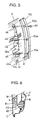
- Figure 6 shows a rear lower part of the completed vehicle door in longitudinal-section.
- the side crash pad 16 installed to the plastic mounting panel P projects from a transverse position where the window glass W is located to a transverse position where the trim unit T is located in a direction from the exterior to the interior of the vehicle.
- the side crash pad 16 is formed with impact absorption ribs 60 configured like cells in the interior thereof which are arranged so as to open at their outside ends. The side crash pad 16 thus configured receives energy due to an impact from a side crash pad 61 secured to the outer panel D2 upon an occurrence of a side crash
- FIG. 7 is the interior door handle 30 which is exploded for the purpose of explaining a step of installing the interior door handle 30 to the plastic mounting panel P.
- the interior door handle 30 is directly secured to a base block 62 formed as a part integral with the plastic mounting panel P without employing separately provided parts.
- the interior door handle 30 comprises a door lock knob 30a and a door release or unlock knob 30b. These knobs 30a and 30b are put between upper and lower brackets 63 and 64 extending from the base block 62 of the plastic mounting panel P as depicted by a double-dotted line so as to turn about a vertical axis in opposite directions.
- the door lock knob 30a has a coupling arm 65 as a part integral therewith and formed with a coupling hole 65a in which a bent end 31c of a cable rod 31a (see Figure 8) of the handle linking cable 31 is fitted.
- the door unlock knob 30b has a coupling arm 66 as a part integral therewith and formed with a coupling hole 66a in which a bent end 31d of a cable rod 31b (see Figure 8) of the handle linking cable 31 is fitted.
- the base block 62 is formed with an intermediate partition 67 extending in parallel to and between the upper and lower brackets 63 and 64.
- the handle linking cable 31 is coupled to the interior door handle 30 installed to the base block 62 of the plastic mounting panel P.
- the handle linking cable 31 comprises the cable rods 31a and 31b and cable rod guide and protect ion sheaths 31A and 31B.
- the cable rod 31a at its extreme end 31c is bent at approximately a right angle and fitted in the coupling hole 65a of the coupling arm 65.
- the cable rod 31b at its extreme end 31d is bent at approximately a right angle and fitted in the coupling hole 66ab of the coupling arm 66.
- the extreme bent ends 31c and 31d of the respective cable rods 31a and 31b are fitted in the coupling holes 65a and 66a of the coupling arms 65 and 66, respectively, first.
- the interior door handle is put and pivotally mounted between the upper bracket 63 and the lower bracket 64 so as to locate the coupling arm 65 of the door lock knob 30a between the upper bracket 63 and the intermediate partition 67 and the coupling arm 66 of the door unlock knob 30b between the intermediate partition 67 and the lower bracket 64.
- the handle linking cable coupling structure makes the upper bracket 63 function as a stopper for preventing the cable rod 31a from slipping off from the coupling arm 65 of the door lock knob 30a.
- the handle linking cable coupling structure makes the intermediate partition 67 function as a stopper for preventing the cable rod 31b from slipping off from the coupling arm 66 of the coupling arm 66 of the door unlock knob 30b.
- the cable rod guide and protection sheaths 31A and 31B are fixedly supported by a bracket 67 of the plastic mounting panel P.
- the handle linking cable coupling structure thus coupling the cable rod 31 to the interior door handle 30 provides reliable power transmission from the door lock knob 30a and the door unlock knob 30b to the door latch unit 33 (see Figure 2).
- Figure 9 shows a door latch unit cover 70 by which the door latch unit 33 is covered and protected.
- the door latch unit cover 70 which is made of a plastic as one piece and has an outer shape in approximately conformity with an outer shape of the door latch unit 33, is fixed to the plastic mounting panel P through fixing brackets 71 and 72 formed as parts integral with the plastic mounting panel P.
- the door latch unit cover 70 may be formed separately from the plastic mounting panel P or may be formed as an appendant part to the plastic mounting panel P.
- the door latch unit cover 70 comprises four integral sections made up as one piece.
- a cover section 73 is located at one of opposite sides of the door latch unit cover 70 to cover a cable rod of a handle linking cable 80 linking the exterior door handle 7 and a cable rod of a cylinder linking cable 81 linking a key cylinder (not shown).
- a cover section 74 is located at another side of the door latch unit cover 70 to cover a cable rod 31a of the handle linking cable 31 linking the door lock knob 30a.
- a cover section 75 is located above the cover section 74 to cover a cable rod 31b of the handle linking cable 31 linking the door unlock knob 30b.
- a cover section 76 is located at lower end of the door latch unit cover 70 to cover a motor (not shown) of the power-driven door latch unit 33.
- FIG 10 shows the door latch unit 33 and its associated parts covered by the door latch unit cover 70 in cross-section.
- the door latch unit 33 is secured to the plastic mounting panel P from the outer side on which the window glass W and the outer panel D2 are located.
- the door latch unit cover 70 protects the door latch unit 33 from an access from the outside of the vehicle with an intention to run away with the vehicle.
- the handle linking cable 31 (see Figures 1 and 2) extending from the interior door handle 30 along the plastic mounting panel P passes through an hole 83 formed in rear part of the plastic mounting panel P so as to extend to the door latch unit 33 crossing the plastic mounting panel P
- the hole 83 in the plastic mounting panel P is covered by the door latch unit cover 70.
- a generally L-shaped reinforcement 90 is welded, or otherwise secured, to the inner panel D1 at a position where the door latch unit 33 is secured by fixing bolts 84 in order to provide reliable fixing stiffness of the door latch unit 33 to the inner panel D1.
- the L-shaped reinforcement 90 which is made of a steel plate, is formed with a generally rectangular center opening 91 through which the body striker passes across when locking the vehicle door and four bolt holes 92 around the rectangular opening 91 through which bolts are inserted and fastened to the inner panel D1 in order to fix the door latch unit 33 to the inner panel D1.
- the L-shaped reinforcement 90 at its lower end is additionally formed with a bottom rack 93.
- the door latch unit 33 itself is comparatively heavy, it is previously supported on the bottom rack 93 of the L-shaped reinforcement 90, so that the work of installing the plastic mounting panel P to the door panel sub-assembly D is made easy, as a result of which, a man-hour in assembling the front door is considerably reduced.
- Figure 12 shows the window glass guide rail 18 of the plastic mounting panel P in cross-section. While a window glass guide rail is conventionally provided separately from the inner panel D1, however, in the vehicle door of the present invention, the window glass guide rail 18 is configured as a part integral with the plastic mounting panel P. This integrated configuration allows the window glass guide rail 18 to be easily completed by simply fitting a packing strip 18P in a groove 18a of the guide rail 18.
- Figure 13 shows the front speaker 32 attached to the speaker mount 14 of the plastic mounting panel P in cross-section.
- the speaker mount 14 projects toward the passenger compartment
- the front speaker 32 is fitted in an opening reinforced by a ring 100 of the speaker mount 14 and is firmly secured by, for example, fixing bolts (not shown) to the speaker mount 14.
- the speaker 32 at its back is provided with a coupler 102 to which a lead wire 101 extending the harness H is connected so as to receive audio signals.
- the plastic mounting panel P is formed with a splash guard 103 extending behind and above the front speaker 32 so as to prevent electric parts associated with the front speaker 32 from, for example, raindrops.
- FIGs 14 and 15 show anchor structures of the plastic mounting panel P for anchoring the harness H and the handle linking cable 31.
- the plastic mounting panel P is formed with a harness anchor 110 as a part integral therewith for anchoring the harness H.
- the harness anchor 110 comprises a pair of L-shaped anchor lugs 110a and 110b arranged oppositely in vertical direction.
- the harness H is positioned substantially vertically and put between the L-shaped anchor lugs 110a and 110b.
- the harness H at opposite parts is bent in opposite directions as shown by arrows so as to bring the opposite parts into engagement with the L-shaped anchor lugs 110a and 110b, respectively.
- the plastic mounting panel P is formed with a cable anchor 111 as a part integral therewith for anchoring the handle linking cable 31.
- the cable anchor 111 comprises a generally J-shaped anchor lug 111a.
- the handle linking cable 31 is inserted between the plastic mounting panel P and the J-shaped anchor lug 111a from above and seat it on the bottom of the J-shaped anchor lug 111a.
- the anchor structure comprising the harness anchor 110 and the cable anchor 111 formed as parts integral with the plastic mounting panel P eliminates any necessity to use anchor clips which have been conventionally prepared separately from the plastic mounting panel P. Therefore, this anchor structure makes wiring work quite simple and easy.
- FIGs 16 and 17 show the access opening covers 22 and 23 before being separated from the plastic mounting panel P, respectively.
- the plastic mounting panel P is prepared as one piece having the access opening covers 22 and 23.
- the plastic plate P is installed to the door panel sub-assembly D with the access opening covers 22 and 23 left joined to the plastic mounting panel P.
- the access opening cover 22 is separated from the plastic mounting panel P by breaking away the joints 20a and attached to the plastic mounting panel P in position to cover up the further access opening 13 which provides an access to the exterior door handle 7 for connecting the handle linking cable 31 to the interior door handle 7.
- the further access opening cover 23 is separated from the plastic mounting panel P by breaking away the joints 21a and attached to the plastic mounting panel P in position to cover up the access opening 12 which provides an access to the inside of the door panel sub-assembly D for installing the window glass W to the window regulator R Specifically, as shown in Figure 16, the access opening cover 22 is formed as an appendant part joined to the plastic mounting panel P by breakable joints 20.
- the access cover 22 has a shock absorbing lattice structure comprising a plurality of ribs 22a extending in opposite directions and arranged in a lattice pattern
- the access opening cover 22 is formed with a hook 22b extending toward the inner panel D1 in conformity with the further access opening 13 so as to surround the shock absorbing lattice structure.
- a rubber packing ring 22c is seated in an annular recess formed around the shock absorbing lattice structure before or after having separated the access opening cover 22 from the plastic mounting panel P and before attaching it to the plastic mounting panel P to cover up the further access opening 13.
- the further access opening cover 23 is formed as an appendant part joined to the plastic mounting panel P by breakable joints 21.
- the further access opening cover 23 is formed with a hook 23b extending toward the inner panel D1 in conformity with the access opening 12.
- a rubber packing ring 23c is seated in an annular recess formed around the hook 23b before or after having separated the further access opening cover 23 from the plastic mounting panel P and before attaching it to the plastic mounting panel P to cover up the access opening 12.
- Figures 18 and 19 show the access opening covers 22 and 23 are attached in position to cover up the access openings 13 and 12, respectively.
- the access opening cover 22 is forced toward the plastic mounting panel P so as to bend and fit the hook 22b into the further access opening 13 from the side of the passenger compartment as indicated by arrows A.
- the hook 22a passes across the periphery 13a of the further access opening 13
- the hook 22a bends back and engages with the periphery 13a of the further access opening 13.
- the access opening cover 22 is easily attached in position to the plastic mounting panel P and is prevented from coming off from the further access opening 13.
- the further access opening cover 23 is forced toward the plastic mounting panel P so as to bend and fit the hook 23b into the access opening 12 from the side of the passenger compartment as indicated by arrows A.
- the hook 23a passes across the periphery 12a of the access opening 12
- the hook 23a bends back and engages with the periphery 1a of the access opening 12, so that the further access opening cover 23 is easily attached in position to the plastic mounting panel P and is prevented from coming off from the access opening 12.
- the plastic mounting panel P having the access openings 12 and 13 provides easy accesses to the exterior door handle 7 and the window regulator R for door assembling work and enables easily closing the access openings 12 and 13 after the door assembling work. Further, the rubber packing rings 22c and 23c provides reliable watertightness of the passenger compartment.
- the plastic mounting panel P having the access opening covers 22 and 23 joined thereto by the breakable joints 20 and 21 is formed by injecting a large amount of plastic material into a large size mold at a stretch
- the plastic mounting panel P is conveyed to a door assembling station.
- the door panel sub-assembly D is prepared separately from the plastic mounting panel P at another station and conveyed to the door assembling station. Because the plastic mounting panel P is configured in the form of substantially rectangular flat plate, it is easy to pile up a plurality of the plastic panels P and to convey a stack of the plastic panels P safely and reliably.
- the necessary functional parts and devices such as the window regulator R, the harness H, etc are mounted to the plastic mounting panel P with the access opening covers 22 and 23 left joined. The assembling work of the functional parts and devices is quite easily achieved as described previously.
- the plastic mounting panel P with the functional parts and devices mounted thereto is installed to the door panel sub-assembly D.
- the door latch unit 33 is secured to the inner panel D1.
- the window glass W is inserted into the door panel sub-assembly D and is coupled to the window regulator R through the access opening 12.
- the handle linking cable 31 is connected to the exterior door handle 7 through the access opening 13.
- the access opening covers 22 and 23 are separated from the plastic mounting panel P and fitted into the access openings 13 and 12, respectively, to cover up the access openings 13 and 12.
- the trim unit T is installed to the door panel semi-assembly D to cover the plastic panel, so as thereby to complete the front door.
- the plastic mounting panel P with the access opening covers 22 and 23 appendant thereto by breakable joints 20 and 21, respectively, can be formed as one piece, large molding equipment and a great quantity of molding material can be put to effective and efficient use and the productivity of the plastic panels is increased.
- the plastic mounting panel P is so formed to have a generally rectangular flat configuration which is efficient. This provides the injection mold with a simple configuration. Moreover, the plastic panels P are easily and stably piled up and safely conveyed.
- the access opening covers 22 and 23 are separated from the plastic mounting panel P after having installed the plastic mounting panel P to the door panel sub-assembly D and having attached the exterior door handle 7 and the window glass W to the door panel sub-assembly D, it is not feared that the access opening covers 22 and 23 are missing before assembling such as during conveyance thereof.
- the appendant pieces are not limited to the access opening covers as long as the appendant parts are formed as parts integral with the plastic panel and installed to the plastic panel after separation.
Landscapes
- Engineering & Computer Science (AREA)
- Mechanical Engineering (AREA)
- Automobile Manufacture Line, Endless Track Vehicle, Trailer (AREA)
- Lock And Its Accessories (AREA)
Claims (8)
- Une porte de véhicule pour un véhicule comprenant une paroi extérieure de porte (D2), une paroi intérieure de porte (D1) formée avec une ouverture (3) et une paroi de montage sur laquelle sont montés les dispositifs fonctionnels (30, 31, 33, 70, R, H) de la porte de véhicule et les membres de la porte associés avec les dispositifs fonctionnels (30, 31, 33, 70, R, H) et qui est installée sur la paroi intérieure de la porte pour fermer l'ouverture (3) de la paroi intérieure de la porte (D1), ladite paroi de montage comprenant une paroi en plastique (P) formée conforme à l'ouverture (3) de la paroi intérieure de la porte (D1), la porte de véhicule caractérisée par: une part structurale en plastique (22, 23) annexée à ladite paroi en plastique (P); et un joint fragile (20, 21) qui fait la liaison entre ladite part structurale en plastique (22, 23) et ladite paroi en plastique (P), où ladite paroi en plastique (P), ladite part structurale en plastique (22, 23) et ledit joint (20, 21) sont formés comme une seule pièce et ladite part structurale (22, 23) est séparée de ladite paroi en plastique (P) détachant le joint (20, 21) installé sur ladite paroi en plastique (P) pendant l'installation de ladite paroi de montage (P) sur ladite paroi intérieure de porte (D1).
- Une porte de véhicule selon la revendication 1, où ladite paroi intérieure de porte (D1) présente une section substantielle de la paroi (D1a) formant une part de la paroi latérale du compartiment de passagers du véhicule.
- Une porte de véhicule selon la revendication 2, où ladite part structurale en plastique (22, 23) est formée dans une position correspondant à ladite section de la paroi (D1a) et installée sur ladite paroi en plastique (P) à une location établie.
- Une porte de véhicule selon la revendication 2, où ladite part structurale en plastique (22, 23) est formée comme un couvercle pour couvrir une ouverture (12, 13) formée dans ladite paroi en plastique (P) pour un accès à l'intérieur de la porte du véhicule pour l'assemblage de la porte du véhicule quand ladite part structurale en plastique (22, 23) est installée sur la paroi en plastique (P).
- Une porte de véhicule selon la revendication 4, où ladite part structurale en plastique (22, 23) est formée avec les nervures (22a) pour absorber les chocs de la paroi extérieure de la porte (D2).
- Procédé d'assemblage pour l'assemblage d'une porte de véhicule qui comprend une paroi extérieure de porte (D2), une paroi intérieure de porte (D1) formée avec une ouverture (3) et une paroi de montage (P) sur laquelle sont montés les dispositifs fonctionnels de la porte de véhicule et les membres de la porte (30, 31, 33, 70, R, H) et qui est installée sur la paroi intérieure de la porte (D1) pour fermer l'ouverture (3) de la paroi intérieure de porte (D1), le procédé d'assemblage comprenantun pas de préparation d'un sous-ensemble de porte (D) de la porte du véhicule comprenant la paroi extérieure (D2) et la paroi intérieure (D1) de la porte et en outre étant caractérisé parun pas de préparation de la paroi de montage comprenant une paroi en plastique (P) formée conforme à l'ouverture (3) de la paroi intérieure de porte (D1), une part structurale en plastique (22, 23) annexée à ladite paroi en plastique (P); et un joint fragile (20, 21) qui fait la liaison entre ladite part structurale en plastique (22, 23) et ladite paroi en plastique (P) de sorte que par cela on forme la paroi de montage comme une seule pièce; etun pas de séparation de ladite part structurale en plastique (22, 23) de ladite paroi en plastique (P) détachant ledit joint (20, 21) de ladite paroi en plastique (P) et installant ladite part structurale en plastique (22, 23) sur la paroi en plastique (P) à une location établie pendant l'opération d'installation de la paroi de montage audit sous-ensemble de porte (D) de la porte du véhicule.
- Un procédé d'assemblage pour une porte de véhicule selon la revendication 6, où ladite part structurale en plastique (22, 23) est séparée de ladite paroi en plastique (P) et installée sur la paroi en plastique (P) après l'installation de la paroi en plastique (P) sur ladite paroi intérieure de porte (D1).
- Une porte de véhicule selon la revendication 6 ou 7, où ladite part structurale en plastique (22, 23) est formée comme un couvercle pour couvrir une ouverture (12, 13) formée dans ladite paroi en plastique (P) pour un accès à l'intérieur de la porte du véhicule pour l'assemblage de la porte du véhicule quand ladite part structurale (22, 23) est installée sur la paroi en plastique (P).
Applications Claiming Priority (2)
| Application Number | Priority Date | Filing Date | Title |
|---|---|---|---|
| JP2000053666A JP3882448B2 (ja) | 2000-02-29 | 2000-02-29 | 自動車用ドア及び自動車用ドアの組立方法 |
| JP2000053666 | 2000-02-29 |
Publications (3)
| Publication Number | Publication Date |
|---|---|
| EP1129873A2 EP1129873A2 (fr) | 2001-09-05 |
| EP1129873A3 EP1129873A3 (fr) | 2003-04-02 |
| EP1129873B1 true EP1129873B1 (fr) | 2004-09-08 |
Family
ID=18575018
Family Applications (1)
| Application Number | Title | Priority Date | Filing Date |
|---|---|---|---|
| EP01103360A Expired - Lifetime EP1129873B1 (fr) | 2000-02-29 | 2001-02-13 | Porte de véhicule et procédé d'assemblage de la porte de véhicule |
Country Status (4)
| Country | Link |
|---|---|
| US (1) | US6449907B2 (fr) |
| EP (1) | EP1129873B1 (fr) |
| JP (1) | JP3882448B2 (fr) |
| DE (1) | DE60105331T2 (fr) |
Families Citing this family (71)
| Publication number | Priority date | Publication date | Assignee | Title |
|---|---|---|---|---|
| WO2001007277A1 (fr) * | 1999-07-22 | 2001-02-01 | Brose Fahrzeugteile Gmbh & Co. Kommanditgesellschaft, Coburg | Ensemble a monter dans une portiere de vehicule |
| DE60016221T2 (de) * | 1999-07-23 | 2005-12-08 | Nippon Sheet Glass Co., Ltd. | Scheibe für fahrzeugtür |
| US7363750B2 (en) * | 2000-07-25 | 2008-04-29 | Alcoa Inc. | Sliding vehicle door with a moveable window assembly |
| FR2812847A1 (fr) * | 2000-08-08 | 2002-02-15 | Sai Automotive Allibert Ind | Porte de vehicule automobile |
| DE60212346T2 (de) * | 2001-03-22 | 2007-06-14 | Intier Automotive Inc., Troy | Verfahren zur herstellung einer fahrzeugtür-baugruppe |
| JP4602614B2 (ja) * | 2001-09-26 | 2010-12-22 | アイシン精機株式会社 | 自動車用ドア |
| US6857688B2 (en) | 2001-10-31 | 2005-02-22 | Lear Corporation | Integrated door module |
| US20030097798A1 (en) * | 2001-11-27 | 2003-05-29 | Staser Brian Hale | Vehicle door module |
| CA2434441A1 (fr) | 2003-01-07 | 2005-01-03 | David Legault | Porte-pieces d'installation de portiere et methode d'assemblage de portiere |
| AU2003201418A1 (en) * | 2002-01-07 | 2003-07-24 | Intier Automotive Closures Inc. | Trim hardware carrier |
| AU2002308083A1 (en) * | 2002-03-11 | 2003-09-22 | Grupo Antolin-Ingenieria, S.A. | Door module for motor vehicles comprising a window regulator with lever |
| US6550846B1 (en) * | 2002-06-05 | 2003-04-22 | Ford Global Technologies, Inc. | Aluminum automotive door assembly |
| DE10230073A1 (de) * | 2002-07-01 | 2004-01-22 | Sai Automotive Sal Gmbh | Kraftfahrzeugtür |
| AU2003270094A1 (en) * | 2002-10-31 | 2004-05-25 | Voestalpine Motion Gmbh | Vehicle door |
| US6676195B1 (en) * | 2002-11-15 | 2004-01-13 | Creative Foam Corp. | Self-sealing door water shield barrier |
| JP2004175171A (ja) * | 2002-11-26 | 2004-06-24 | Mitsubishi Motors Corp | 車両用ドア |
| DE10256266A1 (de) * | 2002-12-03 | 2004-06-24 | Kiekert Ag | Kraftfahrzeugtür |
| US20040122719A1 (en) * | 2002-12-18 | 2004-06-24 | Sabol John M. | Medical resource processing system and method utilizing multiple resource type data |
| FR2851205B1 (fr) * | 2003-02-14 | 2006-04-14 | Arvinmeritor Light Vehicle Sys | Module de porte et procede d'assemblage de porte |
| US7591104B2 (en) * | 2003-07-23 | 2009-09-22 | Ohi Seisakusho Co., Ltd. | Mounting structure of a power window apparatus |
| KR100520202B1 (ko) * | 2003-09-02 | 2005-10-12 | 기아자동차주식회사 | 자동차의 도어글래스 가이드 |
| CN1655960A (zh) * | 2003-09-16 | 2005-08-17 | 安托林-工程集团股份有限公司 | 用于车门的具有防水密封的支撑组件以及该组件的安装步骤 |
| US6938944B2 (en) * | 2004-01-20 | 2005-09-06 | Foamade Industries, Inc. | Water shield with integrated 3-D mirror seal |
| US6908140B1 (en) * | 2004-02-24 | 2005-06-21 | Arvinmeritor Technology, Llc | Door module cable holder |
| US7073843B2 (en) * | 2004-04-06 | 2006-07-11 | Lear Corporation | Trim panel assembly and method of manufacture |
| CA2566275C (fr) * | 2004-06-23 | 2013-02-05 | Intier Automotive Closures Inc. | Module structurel de porte |
| US7059659B2 (en) * | 2004-07-26 | 2006-06-13 | Lear Corporation | Vehicle door barrier panel having removable attachment tabs |
| DE202004011851U1 (de) * | 2004-07-28 | 2004-09-30 | Peguform Gmbh & Co. Kg | Kraftfahrzeug-Hecktür |
| DE102004045453B4 (de) * | 2004-09-20 | 2010-05-12 | Lisa Dräxlmaier GmbH | Vormontageeinheit für ein Kraftfahrzeug |
| JP2008517801A (ja) | 2004-10-22 | 2008-05-29 | ダウ グローバル テクノロジーズ インコーポレイティド | プラスチック強化複合材料造形製品を製造する装置及びプロセス |
| ES2313262T3 (es) * | 2005-03-01 | 2009-03-01 | Grupo Antolin-Ingenieria, S.A. | Modulo de soporte estructural para puertas de vehiculo. |
| US8109559B2 (en) * | 2005-04-18 | 2012-02-07 | Mitsubishi Jidosha Kogyo Kabushiki Kaisha | Door structure of vehicle |
| US20060264554A1 (en) * | 2005-05-17 | 2006-11-23 | Arnold Lustiger | Fiber reinforced polypropylene composite door core modules |
| CN1991122A (zh) * | 2005-12-14 | 2007-07-04 | 德韧环球技术有限公司 | 车门金属构件模块 |
| US20070220811A1 (en) * | 2006-03-23 | 2007-09-27 | Joseph Gustaaf Marie Flendrig | Door assembly with integrated window sealing system |
| KR20080098539A (ko) | 2006-03-23 | 2008-11-10 | 엑손모빌 케미칼 패턴츠 인코포레이티드 | 도어 코어 모듈, 도어 시스템 및 도어 시스템 조립 방법 |
| WO2007111786A1 (fr) | 2006-03-23 | 2007-10-04 | Exxonmobil Chemical Patents Inc. | Ensemble porte avec un système d'étanchéité de fenêtre intégré |
| US20080098655A1 (en) * | 2006-10-31 | 2008-05-01 | Jeffrey Valentage | Integrated bracket for mounting pulley |
| US20070222257A1 (en) * | 2006-03-23 | 2007-09-27 | Joseph Gustaaf Marie Flendrig | Core module for door assembly having integrated reinforcements |
| US20070222249A1 (en) * | 2006-03-23 | 2007-09-27 | Jeffrey Valentage | Interior trim panel with integrated living hinged components |
| WO2007111787A1 (fr) | 2006-03-23 | 2007-10-04 | Exxonmobil Chemical Patents Inc. | Module central de porte |
| US20070220812A1 (en) * | 2006-03-23 | 2007-09-27 | Jeffrey Valentage | Door core module |
| US20070267889A1 (en) * | 2006-03-23 | 2007-11-22 | Flendrig Joseph G M | Door assembly with core module having integrated belt line reinforcement |
| WO2007111785A1 (fr) | 2006-03-23 | 2007-10-04 | Exxonmobil Chemical Patents Inc. | Module central destine a un ensemble porte pourvu de renforts intégrés |
| WO2007111788A1 (fr) | 2006-03-23 | 2007-10-04 | Exxonmobil Chemical Patents Inc. | Module d'âme et d'habillage d'une porte hybride avec composants intégrés |
| US20070222256A1 (en) * | 2006-03-23 | 2007-09-27 | Jeffrey Valentage | Hybrid door core and trim module with integrated components |
| US7338314B2 (en) * | 2006-07-27 | 2008-03-04 | Ford Global Technologies, Llc | Electrical wire routing connector presenter bracket |
| JP5148870B2 (ja) * | 2006-12-15 | 2013-02-20 | 三井金属アクト株式会社 | 自動車のドア構造 |
| JP4466676B2 (ja) | 2007-04-06 | 2010-05-26 | 日産自動車株式会社 | 衝撃吸収部材の取付構造 |
| US20090051193A1 (en) * | 2007-08-22 | 2009-02-26 | Hernandez Everardo A | Window regulator system for a vehicle door assembly |
| US20090056230A1 (en) * | 2007-08-31 | 2009-03-05 | Joseph Gustaaf Flendrig | Door Module With Integrated cable bundle |
| KR100878118B1 (ko) * | 2007-11-08 | 2009-01-14 | 지엠대우오토앤테크놀로지주식회사 | 자동차의 도어 글래스 개폐장치 |
| US20100026018A1 (en) * | 2008-07-31 | 2010-02-04 | International Automotive Components Group North America, Inc. | Lock knob for lock rod in motor vehicle |
| JP2011021673A (ja) * | 2009-07-15 | 2011-02-03 | Nifco Inc | 衝撃吸収部材及び衝撃吸収構造 |
| DE202010007547U1 (de) * | 2010-05-31 | 2011-10-05 | Brose Fahrzeugteile Gmbh & Co. Kg, Hallstadt | Fahrzeugtür mit einem Multifunktionsträger |
| DE102010031013A1 (de) * | 2010-07-06 | 2012-01-12 | Brose Fahrzeugteile Gmbh & Co. Kommanditgesellschaft, Hallstadt | Kraftfahrzeug-Fensterheber |
| FR2964347B1 (fr) * | 2010-09-02 | 2012-09-28 | Faurecia Interieur Ind | Module de porte de vehicule automobile comprenant un systeme leve-vitre |
| DE102010050959A1 (de) * | 2010-11-10 | 2012-05-10 | Gm Global Technology Operations Llc (N.D.Ges.D. Staates Delaware) | Befestigungsanordnung zur Montage einer Zierblende |
| DE202012103532U1 (de) * | 2012-09-17 | 2013-12-20 | Brose Fahrzeugteile Gmbh & Co. Kommanditgesellschaft, Hallstadt | Fahrzeugtür |
| US9731581B2 (en) * | 2013-01-29 | 2017-08-15 | Magna Closures Inc. | Vehicle door and door module with multi-portion door carrier |
| FR3001920B1 (fr) | 2013-02-13 | 2016-07-15 | Renault Sas | Panneau de rigidification en plastique pour ouvrant avec fixation d'un systeme de leve-vitre |
| JP2016030467A (ja) * | 2014-07-25 | 2016-03-07 | トヨタ自動車株式会社 | 車両用ドア構造 |
| JP6278915B2 (ja) * | 2015-02-20 | 2018-02-14 | 株式会社ニフコ | 荷重伝達部材 |
| DE102015217353A1 (de) * | 2015-05-05 | 2016-11-10 | Brose Fahrzeugteile Gmbh & Co. Kommanditgesellschaft, Bamberg | Trägervorrichtung für ein Kraftfahrzeug |
| CN107848380A (zh) * | 2015-07-23 | 2018-03-27 | 麦格纳国际公司 | 车门组件 |
| US10406893B2 (en) * | 2016-06-29 | 2019-09-10 | GM Global Technology Operations LLC | Inner support panel for mounting a hardware module of a vehicle door assembly |
| DE102016008728B3 (de) * | 2016-07-21 | 2017-07-27 | Brose Fahrzeugteile Gmbh & Co. Kommanditgesellschaft, Bamberg | Ausbrechelement für einen als Nass-/Trockenraumtrennung ausgeführten Modulträger einer Tür oder Klappe eines Kraftfahrzeugs |
| US10071665B2 (en) * | 2016-10-27 | 2018-09-11 | Honda Motor Co., Ltd. | Grab handle assembly for use in a vehicle |
| US10647183B2 (en) * | 2017-06-02 | 2020-05-12 | Magna Closures Inc. | Vehicle closure panel assembly and carrier assembly therefor |
| US20180354349A1 (en) * | 2017-06-12 | 2018-12-13 | Magna Closures Inc. | Door assembly with split carrier module |
| US10967714B2 (en) | 2017-09-25 | 2021-04-06 | Ford Global Technologies, Llc | Collapsible side door latch module |
Family Cites Families (13)
| Publication number | Priority date | Publication date | Assignee | Title |
|---|---|---|---|---|
| DE3423827A1 (de) * | 1984-06-04 | 1985-02-14 | Stübbe GmbH, 2940 Wilhemshaven | Tuer aus kunststoff fuer kraftfahrzeuge |
| US4868715A (en) * | 1988-05-31 | 1989-09-19 | Scosche Industries, Inc. | Break-away panel structure for radio in-dash installation kit |
| US5535553A (en) * | 1994-11-16 | 1996-07-16 | General Motors Corporation | Superplug vehicle door module |
| DE19511105C1 (de) * | 1995-03-25 | 1996-11-21 | Brose Fahrzeugteile | Zweischalige Fahrzeugtür mit einem auf einer Trägerplatte vormontierten doppelsträngigen Seilfensterheber |
| JP3067092B2 (ja) | 1995-12-08 | 2000-07-17 | 矢崎総業株式会社 | 自動車用ドア |
| US6000959A (en) * | 1996-02-07 | 1999-12-14 | Lear Corporation | Door panel wiring system |
| US5820191A (en) * | 1996-07-03 | 1998-10-13 | Freightliner Corporation | Inner-door panel for a vehicle |
| US5890321A (en) * | 1996-08-05 | 1999-04-06 | General Motors Corporation | Window regulator mounting panel |
| US5855096A (en) * | 1996-12-13 | 1999-01-05 | General Motors Corporation | Rod orienting receptacles for door module installation |
| US5937584A (en) * | 1997-06-13 | 1999-08-17 | General Motors Corporation | Integral support for mounting of door module |
| DE19732225B4 (de) * | 1997-07-26 | 2004-05-19 | Kiekert Ag | Kraftfahrzeugtür |
| US6367202B1 (en) * | 1998-04-22 | 2002-04-09 | Visteon Global Technologies, Inc. | Door module having an enclosure and speakers for an automotive vehicle |
| DE19833185A1 (de) * | 1998-07-23 | 2000-02-03 | Ticona Gmbh | Türmodul für Kraftfahrzeuge mit Funktionselementen aus Kunststoff |
-
2000
- 2000-02-29 JP JP2000053666A patent/JP3882448B2/ja not_active Expired - Fee Related
-
2001
- 2001-02-13 DE DE60105331T patent/DE60105331T2/de not_active Expired - Lifetime
- 2001-02-13 EP EP01103360A patent/EP1129873B1/fr not_active Expired - Lifetime
- 2001-02-21 US US09/790,313 patent/US6449907B2/en not_active Expired - Fee Related
Also Published As
| Publication number | Publication date |
|---|---|
| EP1129873A2 (fr) | 2001-09-05 |
| EP1129873A3 (fr) | 2003-04-02 |
| US6449907B2 (en) | 2002-09-17 |
| US20020007598A1 (en) | 2002-01-24 |
| DE60105331T2 (de) | 2005-09-22 |
| JP3882448B2 (ja) | 2007-02-14 |
| DE60105331D1 (de) | 2004-10-14 |
| JP2001239836A (ja) | 2001-09-04 |
Similar Documents
| Publication | Publication Date | Title |
|---|---|---|
| EP1129873B1 (fr) | Porte de véhicule et procédé d'assemblage de la porte de véhicule | |
| EP1129874B1 (fr) | Porte de véhicule et procédé d'assemblge de la porte de véhicule | |
| EP1129875B1 (fr) | Porte de véhicule | |
| MX2007008284A (es) | Modulo portante para puertas de vehiculo y procedimiento de montaje. | |
| EP1630327B1 (fr) | Porte de véhicule avec poignée de porte | |
| US6805398B2 (en) | Structure of tail gate | |
| EP1215065B1 (fr) | Procédé d'assemblage d'une porte | |
| US8443552B2 (en) | Mounting structure of door guard bar | |
| CN107444081B (zh) | 具有可收缩的承载架的车门组件 | |
| US20080289259A1 (en) | Integrated Channel Regulator for Vehicle Door | |
| JPS6393621A (ja) | ドア用カートリッジ・アセンブリーとドア・アセンブリーおよびドアの組立方法 | |
| CA2434441A1 (fr) | Porte-pieces d'installation de portiere et methode d'assemblage de portiere | |
| US20040128917A1 (en) | Trim door hardware carrier and method of assembling vehicle door | |
| US7111893B2 (en) | Hinged door module bracket | |
| JP5412479B2 (ja) | 車両のスライドドア装置 | |
| US6471266B1 (en) | Door latch cover for automotive vehicle | |
| JP3888339B2 (ja) | 自動車用ドア構造 | |
| EP1215359A1 (fr) | Dispositif de lève-vitre | |
| CA1332620C (fr) | Portiere modulaire pour vehicule automobile | |
| JP3835407B2 (ja) | 自動車用ドア | |
| JP2001171353A (ja) | バックドアロックカバーの取付構造 | |
| KR100346470B1 (ko) | 자동차의 인사이드 핸들 하우징 장착 구조 | |
| KR20140062182A (ko) | 차량용 해치 프레임 | |
| KR20010055943A (ko) | 자동차의 도어 | |
| KR19980029522A (ko) | 차량용 인더커버 |
Legal Events
| Date | Code | Title | Description |
|---|---|---|---|
| PUAI | Public reference made under article 153(3) epc to a published international application that has entered the european phase |
Free format text: ORIGINAL CODE: 0009012 |
|
| AK | Designated contracting states |
Kind code of ref document: A2 Designated state(s): AT BE CH CY DE DK ES FI FR GB GR IE IT LI LU MC NL PT SE TR |
|
| AX | Request for extension of the european patent |
Free format text: AL;LT;LV;MK;RO;SI |
|
| RIN1 | Information on inventor provided before grant (corrected) |
Inventor name: SHOUNO, NOBURU Inventor name: NISHIKAWA, IKUO Inventor name: KAWAMOTO, CHIKASHI Inventor name: OGAWA, KENICHI |
|
| PUAL | Search report despatched |
Free format text: ORIGINAL CODE: 0009013 |
|
| AK | Designated contracting states |
Kind code of ref document: A3 Designated state(s): AT BE CH CY DE DK ES FI FR GB GR IE IT LI LU MC NL PT SE TR |
|
| AX | Request for extension of the european patent |
Extension state: AL LT LV MK RO SI |
|
| 17P | Request for examination filed |
Effective date: 20031001 |
|
| AKX | Designation fees paid |
Designated state(s): DE |
|
| GRAP | Despatch of communication of intention to grant a patent |
Free format text: ORIGINAL CODE: EPIDOSNIGR1 |
|
| GRAS | Grant fee paid |
Free format text: ORIGINAL CODE: EPIDOSNIGR3 |
|
| GRAA | (expected) grant |
Free format text: ORIGINAL CODE: 0009210 |
|
| AK | Designated contracting states |
Kind code of ref document: B1 Designated state(s): DE |
|
| REG | Reference to a national code |
Ref country code: IE Ref legal event code: FG4D |
|
| REF | Corresponds to: |
Ref document number: 60105331 Country of ref document: DE Date of ref document: 20041014 Kind code of ref document: P |
|
| PLBE | No opposition filed within time limit |
Free format text: ORIGINAL CODE: 0009261 |
|
| STAA | Information on the status of an ep patent application or granted ep patent |
Free format text: STATUS: NO OPPOSITION FILED WITHIN TIME LIMIT |
|
| 26N | No opposition filed |
Effective date: 20050609 |
|
| PGFP | Annual fee paid to national office [announced via postgrant information from national office to epo] |
Ref country code: DE Payment date: 20110208 Year of fee payment: 11 |
|
| REG | Reference to a national code |
Ref country code: DE Ref legal event code: R119 Ref document number: 60105331 Country of ref document: DE Effective date: 20120901 |
|
| PG25 | Lapsed in a contracting state [announced via postgrant information from national office to epo] |
Ref country code: DE Free format text: LAPSE BECAUSE OF NON-PAYMENT OF DUE FEES Effective date: 20120901 |