EP1129678A2 - Prothesenfestes Verriegelungselement für eine Verriegelung zwischen einem über einen Amputationsstumpf zu ziehenden Strumpf und einer Prothese - Google Patents
Prothesenfestes Verriegelungselement für eine Verriegelung zwischen einem über einen Amputationsstumpf zu ziehenden Strumpf und einer Prothese Download PDFInfo
- Publication number
- EP1129678A2 EP1129678A2 EP01104245A EP01104245A EP1129678A2 EP 1129678 A2 EP1129678 A2 EP 1129678A2 EP 01104245 A EP01104245 A EP 01104245A EP 01104245 A EP01104245 A EP 01104245A EP 1129678 A2 EP1129678 A2 EP 1129678A2
- Authority
- EP
- European Patent Office
- Prior art keywords
- locking element
- element according
- locking
- prosthesis
- relative movement
- Prior art date
- Legal status (The legal status is an assumption and is not a legal conclusion. Google has not performed a legal analysis and makes no representation as to the accuracy of the status listed.)
- Withdrawn
Links
Images

Classifications
-
- A—HUMAN NECESSITIES
- A61—MEDICAL OR VETERINARY SCIENCE; HYGIENE
- A61F—FILTERS IMPLANTABLE INTO BLOOD VESSELS; PROSTHESES; DEVICES PROVIDING PATENCY TO, OR PREVENTING COLLAPSING OF, TUBULAR STRUCTURES OF THE BODY, e.g. STENTS; ORTHOPAEDIC, NURSING OR CONTRACEPTIVE DEVICES; FOMENTATION; TREATMENT OR PROTECTION OF EYES OR EARS; BANDAGES, DRESSINGS OR ABSORBENT PADS; FIRST-AID KITS
- A61F2/00—Filters implantable into blood vessels; Prostheses, i.e. artificial substitutes or replacements for parts of the body; Appliances for connecting them with the body; Devices providing patency to, or preventing collapsing of, tubular structures of the body, e.g. stents
- A61F2/50—Prostheses not implantable in the body
- A61F2/78—Means for protecting prostheses or for attaching them to the body, e.g. bandages, harnesses, straps, or stockings for the limb stump
-
- A—HUMAN NECESSITIES
- A61—MEDICAL OR VETERINARY SCIENCE; HYGIENE
- A61F—FILTERS IMPLANTABLE INTO BLOOD VESSELS; PROSTHESES; DEVICES PROVIDING PATENCY TO, OR PREVENTING COLLAPSING OF, TUBULAR STRUCTURES OF THE BODY, e.g. STENTS; ORTHOPAEDIC, NURSING OR CONTRACEPTIVE DEVICES; FOMENTATION; TREATMENT OR PROTECTION OF EYES OR EARS; BANDAGES, DRESSINGS OR ABSORBENT PADS; FIRST-AID KITS
- A61F2/00—Filters implantable into blood vessels; Prostheses, i.e. artificial substitutes or replacements for parts of the body; Appliances for connecting them with the body; Devices providing patency to, or preventing collapsing of, tubular structures of the body, e.g. stents
- A61F2/02—Prostheses implantable into the body
- A61F2/30—Joints
- A61F2002/30001—Additional features of subject-matter classified in A61F2/28, A61F2/30 and subgroups thereof
- A61F2002/30316—The prosthesis having different structural features at different locations within the same prosthesis; Connections between prosthetic parts; Special structural features of bone or joint prostheses not otherwise provided for
- A61F2002/30329—Connections or couplings between prosthetic parts, e.g. between modular parts; Connecting elements
- A61F2002/30433—Connections or couplings between prosthetic parts, e.g. between modular parts; Connecting elements using additional screws, bolts, dowels, rivets or washers e.g. connecting screws
-
- A—HUMAN NECESSITIES
- A61—MEDICAL OR VETERINARY SCIENCE; HYGIENE
- A61F—FILTERS IMPLANTABLE INTO BLOOD VESSELS; PROSTHESES; DEVICES PROVIDING PATENCY TO, OR PREVENTING COLLAPSING OF, TUBULAR STRUCTURES OF THE BODY, e.g. STENTS; ORTHOPAEDIC, NURSING OR CONTRACEPTIVE DEVICES; FOMENTATION; TREATMENT OR PROTECTION OF EYES OR EARS; BANDAGES, DRESSINGS OR ABSORBENT PADS; FIRST-AID KITS
- A61F2/00—Filters implantable into blood vessels; Prostheses, i.e. artificial substitutes or replacements for parts of the body; Appliances for connecting them with the body; Devices providing patency to, or preventing collapsing of, tubular structures of the body, e.g. stents
- A61F2/02—Prostheses implantable into the body
- A61F2/30—Joints
- A61F2002/30001—Additional features of subject-matter classified in A61F2/28, A61F2/30 and subgroups thereof
- A61F2002/30316—The prosthesis having different structural features at different locations within the same prosthesis; Connections between prosthetic parts; Special structural features of bone or joint prostheses not otherwise provided for
- A61F2002/30329—Connections or couplings between prosthetic parts, e.g. between modular parts; Connecting elements
- A61F2002/30476—Connections or couplings between prosthetic parts, e.g. between modular parts; Connecting elements locked by an additional locking mechanism
- A61F2002/30505—Connections or couplings between prosthetic parts, e.g. between modular parts; Connecting elements locked by an additional locking mechanism spring biased
-
- A—HUMAN NECESSITIES
- A61—MEDICAL OR VETERINARY SCIENCE; HYGIENE
- A61F—FILTERS IMPLANTABLE INTO BLOOD VESSELS; PROSTHESES; DEVICES PROVIDING PATENCY TO, OR PREVENTING COLLAPSING OF, TUBULAR STRUCTURES OF THE BODY, e.g. STENTS; ORTHOPAEDIC, NURSING OR CONTRACEPTIVE DEVICES; FOMENTATION; TREATMENT OR PROTECTION OF EYES OR EARS; BANDAGES, DRESSINGS OR ABSORBENT PADS; FIRST-AID KITS
- A61F2/00—Filters implantable into blood vessels; Prostheses, i.e. artificial substitutes or replacements for parts of the body; Appliances for connecting them with the body; Devices providing patency to, or preventing collapsing of, tubular structures of the body, e.g. stents
- A61F2/50—Prostheses not implantable in the body
- A61F2002/5096—Ball-and-socket joints
- A61F2002/5098—Ball-and-socket joints with rotation-limiting means
-
- A—HUMAN NECESSITIES
- A61—MEDICAL OR VETERINARY SCIENCE; HYGIENE
- A61F—FILTERS IMPLANTABLE INTO BLOOD VESSELS; PROSTHESES; DEVICES PROVIDING PATENCY TO, OR PREVENTING COLLAPSING OF, TUBULAR STRUCTURES OF THE BODY, e.g. STENTS; ORTHOPAEDIC, NURSING OR CONTRACEPTIVE DEVICES; FOMENTATION; TREATMENT OR PROTECTION OF EYES OR EARS; BANDAGES, DRESSINGS OR ABSORBENT PADS; FIRST-AID KITS
- A61F2/00—Filters implantable into blood vessels; Prostheses, i.e. artificial substitutes or replacements for parts of the body; Appliances for connecting them with the body; Devices providing patency to, or preventing collapsing of, tubular structures of the body, e.g. stents
- A61F2/50—Prostheses not implantable in the body
- A61F2/68—Operating or control means
- A61F2002/6818—Operating or control means for braking
-
- A—HUMAN NECESSITIES
- A61—MEDICAL OR VETERINARY SCIENCE; HYGIENE
- A61F—FILTERS IMPLANTABLE INTO BLOOD VESSELS; PROSTHESES; DEVICES PROVIDING PATENCY TO, OR PREVENTING COLLAPSING OF, TUBULAR STRUCTURES OF THE BODY, e.g. STENTS; ORTHOPAEDIC, NURSING OR CONTRACEPTIVE DEVICES; FOMENTATION; TREATMENT OR PROTECTION OF EYES OR EARS; BANDAGES, DRESSINGS OR ABSORBENT PADS; FIRST-AID KITS
- A61F2/00—Filters implantable into blood vessels; Prostheses, i.e. artificial substitutes or replacements for parts of the body; Appliances for connecting them with the body; Devices providing patency to, or preventing collapsing of, tubular structures of the body, e.g. stents
- A61F2/50—Prostheses not implantable in the body
- A61F2/68—Operating or control means
- A61F2002/6854—Operating or control means for locking or unlocking a joint
-
- A—HUMAN NECESSITIES
- A61—MEDICAL OR VETERINARY SCIENCE; HYGIENE
- A61F—FILTERS IMPLANTABLE INTO BLOOD VESSELS; PROSTHESES; DEVICES PROVIDING PATENCY TO, OR PREVENTING COLLAPSING OF, TUBULAR STRUCTURES OF THE BODY, e.g. STENTS; ORTHOPAEDIC, NURSING OR CONTRACEPTIVE DEVICES; FOMENTATION; TREATMENT OR PROTECTION OF EYES OR EARS; BANDAGES, DRESSINGS OR ABSORBENT PADS; FIRST-AID KITS
- A61F2/00—Filters implantable into blood vessels; Prostheses, i.e. artificial substitutes or replacements for parts of the body; Appliances for connecting them with the body; Devices providing patency to, or preventing collapsing of, tubular structures of the body, e.g. stents
- A61F2/50—Prostheses not implantable in the body
- A61F2/78—Means for protecting prostheses or for attaching them to the body, e.g. bandages, harnesses, straps, or stockings for the limb stump
- A61F2/7812—Interface cushioning members placed between the limb stump and the socket, e.g. bandages or stockings for the limb stump
- A61F2002/7818—Stockings or socks for the limb stump
-
- A—HUMAN NECESSITIES
- A61—MEDICAL OR VETERINARY SCIENCE; HYGIENE
- A61F—FILTERS IMPLANTABLE INTO BLOOD VESSELS; PROSTHESES; DEVICES PROVIDING PATENCY TO, OR PREVENTING COLLAPSING OF, TUBULAR STRUCTURES OF THE BODY, e.g. STENTS; ORTHOPAEDIC, NURSING OR CONTRACEPTIVE DEVICES; FOMENTATION; TREATMENT OR PROTECTION OF EYES OR EARS; BANDAGES, DRESSINGS OR ABSORBENT PADS; FIRST-AID KITS
- A61F2220/00—Fixations or connections for prostheses classified in groups A61F2/00 - A61F2/26 or A61F2/82 or A61F9/00 or A61F11/00 or subgroups thereof
- A61F2220/0025—Connections or couplings between prosthetic parts, e.g. between modular parts; Connecting elements
-
- A—HUMAN NECESSITIES
- A61—MEDICAL OR VETERINARY SCIENCE; HYGIENE
- A61F—FILTERS IMPLANTABLE INTO BLOOD VESSELS; PROSTHESES; DEVICES PROVIDING PATENCY TO, OR PREVENTING COLLAPSING OF, TUBULAR STRUCTURES OF THE BODY, e.g. STENTS; ORTHOPAEDIC, NURSING OR CONTRACEPTIVE DEVICES; FOMENTATION; TREATMENT OR PROTECTION OF EYES OR EARS; BANDAGES, DRESSINGS OR ABSORBENT PADS; FIRST-AID KITS
- A61F2220/00—Fixations or connections for prostheses classified in groups A61F2/00 - A61F2/26 or A61F2/82 or A61F9/00 or A61F11/00 or subgroups thereof
- A61F2220/0025—Connections or couplings between prosthetic parts, e.g. between modular parts; Connecting elements
- A61F2220/0041—Connections or couplings between prosthetic parts, e.g. between modular parts; Connecting elements using additional screws, bolts, dowels or rivets, e.g. connecting screws
Definitions
- the invention relates to a prosthesis-proof Locking element for locking between one over an amputation stump and one Prosthesis, with a retraction mechanism for one on the stocking permanently connected locking pin.
- the prosthesis wearer rolls a bag-like one made of silicone Stocking, a so-called silicone liner, over the stump. Forces are transferred from a prosthesis by means of this stocking the stump over one fixed in the stocking bottom Locking pin and a prosthesis-proof Locking element transmitted when the locking pin inserted into a receptacle of a feed mechanism, drawn in and locked.
- This locking system will also regularly referred to as a clutch lock. Feeding the a toothed locking pin in the An appropriate toothing takes place having worm clutch of a feeder, of which is the locking pin, mostly as a locking pin designated, from the outside with a rotary movement in the recording of the locking system for a secure fit can be and in which it is then locked. This Feed mechanism with feed and cover.
- Unlocking device for the locking pin in the According to the state of the art, the recording is immobile with the Prosthesis connected so that a firm connection of the prosthesis is given over the silicone liner with the stump. This rigid connection, just something through the flexibility of the Stockings diminished, ultimately prevents occurring Tensile forces the prosthesis from the stump of the prosthesis wearer to be able to solve.
- Unlocking device can interlock the Locking device of the feed mechanism and the Locking pin can be released again and is then the Patient able to remove the stocking or silicone liner from of the prosthesis, with which the stocking and prosthesis again are separated.
- the retraction mechanism for the locking pin or one Locking pin can still be state of the art correspond.
- the possibility of one is essential Relative movement between this feed mechanism and the prosthesis-proof holder. This is the possibility of one
- the prosthesis can move with respect to the stump, which do not have the same in the intake mechanism locked locking pin or locking pin the silicone liner and thus on the stump with the corresponding forces are transmitted. Much more is consciously admitted that a relative movement too may take place. Naturally, this should not be arbitrary be, but ultimately limited by appropriate measures be maintained so that the normal function of the prosthesis remains.
- the Relative movement is a movement with three degrees of freedom. This ensures that one in all directions Relative movement can also take place and such Relative movement with every movement of the stump too can take place.
- a relative movement has proven to be extremely useful proven to have at least one rotationally symmetrical, especially a circularly symmetrical movement component having. There is no such movement spatial shift, but essentially perform this just a kind of kinking of the prosthesis on the Connection and thus opposite the stump.
- connection Delay elements, braking elements or the like do not have to be trained separately and consequently that Volume of the locking element fixed to the prosthesis can also be kept comparatively small.
- connection Joint is the Relative movements with three degrees of freedom are also allowed. It is particularly thought that the connection is designed as a ball joint, which makes it rotationally symmetrical or circular movements in all degrees of freedom as Relative movement are made possible.
- connection may be provided as a spherical layer joint. On such ball joint corresponds largely to that Function of a ball joint, but lacks that of Spherical shell sections recorded, spherical layer trained joint body on opposite polar caps an axis of symmetry, which is also an axis of rotation.
- the Including an upper and a lower part with each has half-shell-shaped sliding surfaces for Inclusion of a rotationally symmetrical, in particular spherical joint body with the retraction mechanism.
- the Advantages of the locking element according to the invention can also be carried by retrofitting an existing prosthesis come.
- the Locking element In a further technical configuration of the Locking element according to the invention is provided that The upper and lower parts are screwed together in such a way that the frictional force between the screws Sliding surfaces and the joint body is adjustable. By this measure becomes a movement of the prosthesis relative to the Blunt at first immediately, but usually not completely, slowed down. The then transmitted are correspondingly small Powers.
- This adjustment possibility of the relative movement damping force allows further individual adjustment and matching to a prosthesis wearer or the prosthesis.
- a particularly fine adjustment option is then given if a further design is provided, that the screws each against the force of a spring are screwable. In addition to the sensitive detection of this Screws are largely against loosening secured.
- circumferential groove can be provided.
- Such a recess can have either the upper or the lower part or can both carry corresponding grooving.
- Objective of the measure is the area of the sliding surfaces between top and bottom Separate lower part by a slot.
- Locking element In a further technical configuration of the Locking element according to the invention is provided that an axis of symmetry and rotation of the joint body and the axis a pen-like move-in and move-in. Unlocking device of the feed mechanism normal are perpendicular to each other. This is on the one hand a good introduction of force from the locking pin given on the retraction mechanism on the joint body and to others for the relative movement an exact orientation of the Directions of movement.
- an opening Have jacket wall for the implementation of Feed device in the form of, for example, a worm wheel and / or a locking and unlocking device in the state the technology is regularly designed like a pen for Locking pin. This is conveniently by Circumference of the opening a rotation of the joint body limited around its axis of symmetry and rotation. this happens by a stop of a guide for and / or one pin-shaped feeder or supply and Unlocking device itself against in particular vertically rising edges of the limit of the opening (s).
- the upper part has an opening has which penetrates by an approach of the joint body becomes. Also through this approach, the breakthrough of the Passing through the upper part, the relative movement is limited. In particular, this measure results in a tilting movement by hitting the shoulder on the edge of the opening limited. It has further proven to be expedient here if the approach and opening of the top rotationally symmetrical, in particular circularly symmetrical are formed, in particular symmetrical to that already mentioned symmetry and rotation axis of the joint body. By these measures will also make the relative movement symmetrical limited.
- the approach itself can form the recording or on such be connected to the inclusion of the Locking pin is used and / or a support for the Form butt.
- joint body is advantageous and / or the joint body itself made of a plastic, in particular made of a polyamide. As a result, the weight of the Locking element reached. At the same time, however, it is extremely stable without being brittle.
- the locking element according to the invention can be extremely have a low overall height if on a Worm clutch with a worm wheel of comparatively large diameter of the feed device is dispensed with. Then a feed mechanism is preferred, which a one in a recording inserted locking pin against Pulling out locking locking device having.
- This is especially smooth trained locking pin can, for example Locking in the known pistols for cartridges for Adhesives or foams are formed, in which the Inserting the bottom of the cartridge, from a trigger in Feeded, often smooth, rod in each advanced position is locked immediately and no longer can be withdrawn.
- the locking device has a clamping jaw, has a clamp or the like, which by a Wedge effect the locking pin in its holder automatically clamps.
- a wedge effect very large clamping and thus the locking pin defining forces are created that are safe unintentional pulling out of the locking pin exclude.
- the Clamping bracket or the like releasing unlocking device provided that from a simple pull or push element can exist because a simple pull or push on the jaws, bring the clamp or the like out of its wedge position can, with which its clamping effect is canceled.
- the intake of the Locking pin in its inclusion with its help more is possible.
- the introduction the locking pin under weight should be sufficient can by one at the Locking pin tethered by the an outlet that is fixed to the prosthesis, an extensive one Pulling the locking pin into its receptacle be ensured because by pulling on the free end of the Traction device, a rope, a wire or the like, this retraction can be ensured.
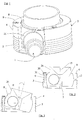
- Figure 1 shows an isometric view as a Articulated locking element according to the invention in an isometric representation.
- the locking element z. B. for the Connection of a prosthesis to a lower and / or Use the thigh stump.
- the embodiment of the locking element according to the Invention is a joint that has a relative movement between the feed mechanism 1 or that of the latter in the receptacle 3 fixed locking pin and a prosthesis-proof Admission 2 in three degrees of freedom.
- This is the Locking element with a connection between the Recording 2 and the feed mechanism 1 like a Ball joint provided, namely with a ball layer joint.
- the locking element is of a structural design according to the invention provided with a receptacle 2, which in a Upper part 4 and a lower part 5 is divided.
- the top 4 like the lower part 5 each have a half-shell trained sliding surfaces 6, 7 with which the receptacle 2 a joint body 8 according to FIGS. 8 to 11.
- This Joint body 8 is rotationally symmetrical, here spherical for the border formed by the sliding surfaces 6,7.
- a elliptical training would also be possible.
- the top 4 and the lower part 5 are particularly in terms of Sliding surfaces 6.7 largely symmetrical here.
- the joint body 8 is further than a spherical layer body 16 executed, i.e. two opposite polar caps are missing.
- the upper part 4 and the lower part 5 are by screws 9 connected with each other.
- the heads 30 of the screws 9 are in Recesses 10 recessed in the upper part 4 and are each against the force of a spring 31, for example as a compression spring or designed like a snap ring, tightened.
- a spring 31 for example as a compression spring or designed like a snap ring
- the upper part 4 has Embodiment a separating the sliding surfaces 6,7 circumferential groove 12.
- the groove 12 is radially as deep going that the screws 9 the groove 12 free enforce, cf. Fig. 2 and 3. This measure can almost a clamping effect of the upper part 4 on the Joint body 8 can be reached.
- the receptacle 2 like the joint body 8, preferably consists of a plastic, especially polyamide, it can be useful for the screws 9 separate To provide threaded inserts in the lower part 5. This also in With regard to the possibility of the exact setting of the Force on the joint body 8 via the sliding surfaces 6,7.
- the circumferential jacket wall 13 of the lower part 5 has one Surface structuring for a firm introduction into a appropriate recess of the prosthesis, e.g. like here circumferential grooves 14 which form an undercut positive connection with the prosthesis in axial Direction, with respect to an axis of symmetry 15, allow.
- the spherical layer body 16 takes the retraction and Ver. Unlocking device of the feed mechanism 1 in a receiving bore 17, see. Fig. 1.
- the axis 18 this receiving bore and the axis of symmetry 15 are Normal, i.e. H. axes perpendicular to a plane, which levels are preferably perpendicular to each other. Here these are the drawing plane with the axis 18 as normal and 8, a horizontal plane 19 as Normal of axis 15.
- a spacer ring 20 for the Move-in and move-in Unlocking device of the Feed mechanism 1 in conventional technology per se brought in.
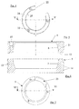
- the circumference this breakthrough, cf. 4 and 7, determines the possible rotation of the joint body 8 about its symmetry and Axis of rotation 15 by a stop of the spacer ring 20 and / or a pin-shaped retraction and or unlocking device on the in particular vertically rising edges of the openings 22,23. Through this Measure, the relative movement about this axis 15 is limited.
- a conventional feed mechanism that mostly a rotatable worm wheel for retracting the then a corresponding toothing Locking pin can also be removed if, for example toothed or even smooth locking pin provided by a suitably trained, articulated body-fixed clamping device is held.
- a suitably trained, articulated body-fixed clamping device Such Clamps with wedges, clamps or the same as they are, for example, in known cartridge pistols Finding use are well known in the art.
- An unlocking of such a clamping device can, like in the embodiment, tangential through the Openings 22, 23 and the receiving bore 17 are provided that can turn out to be considerably smaller, or also above and / or below the locking element, if suitable deflection devices for one Unlocking pin and / or an unlocking cable provided become.
- the upper part 4 also has one in its upper side 24 Opening 25 on that of an approach 26 of Joint body 8 is penetrated.
- the axial dimension of this Approach 26 is chosen so that by a stop of the Approach 26 to the edge of the opening 25 the Relative movement also in the two other degrees of freedom is limited, cf. Fig. 3.
- This limitation is one symmetrical, since the opening 25 as well as the approach 26 are circularly symmetrical.
- the maximum possible Opening angle 2 ⁇ is limited to a total of about 30 °, with which due to the symmetry with respect to the axis 15 a deflection ⁇ of about 15 ° is possible.
- the approach 26 can be of the conventional type of immediate Serve recording a locking pin of a stump and have or have a corresponding receptacle 3 for this purpose such recording can also be connected to the extension 26.
Landscapes
- Health & Medical Sciences (AREA)
- Cardiology (AREA)
- Oral & Maxillofacial Surgery (AREA)
- Transplantation (AREA)
- Engineering & Computer Science (AREA)
- Biomedical Technology (AREA)
- Heart & Thoracic Surgery (AREA)
- Vascular Medicine (AREA)
- Life Sciences & Earth Sciences (AREA)
- Animal Behavior & Ethology (AREA)
- General Health & Medical Sciences (AREA)
- Public Health (AREA)
- Veterinary Medicine (AREA)
- Prostheses (AREA)
Abstract
Description
- Fig. 1:
- in einer isometrischen Darstellung ein Verriegelungselement nach der Erfindung,
- Fig. 2:
- das Verriegelungselement nach Fig. 1 in einer geschnittenen Darstellung,
- Fig. 3:
- eine Ansicht gemäß Fig. 2 mit einer maximalen Auslenkung des Gelenkkörpers,
- Fig. 4:
- eine Draufsicht auf ein Oberteil einer Aufnahme,
- Fig. 5:
- einen Schnitt gemäß der Linie V,V in Fig. 4,
- Fig. 6:
- einen Schnitt durch ein Unterteil einer Aufnahme gemäß der Linie VI,VI in Fig. 7,
- Fig. 7:
- eine Draufsicht auf ein Unterteil,
- Fig. 8:
- eine seitliche Ansicht eines Gelenkkörpers,
- Fig. 9:
- eine Draufsicht auf den Gelenkkörper nach Fig. 8,
- Fig.10:
- einen Schnitt gemäß der Linie X,X in Fig. 8 durch einen Gelenkkörper und
- Fig.11:
- einen Schnitt gemäß der Linie XI, XI in Fig. 9.
Claims (25)
- Prothesenfestes Verriegelungselement für eine Verriegelung zwischen einem über einen Amputationsstumpf zu ziehenden Strumpf und einer Prothese, mit einer Einzugsmechanik für einen an dem Strumpf fest angeschlossenen Verriegelungsstift, gekennzeichnet durch eine eine Relativbewegung zwischen der Einzugsmechanik (1) und einer prothesenfeste Aufnahme (2) zulassenden Verbindung derselben.
- Verriegelungselement nach Anspruch 1, gekennzeichnet durch eine Relativbewegung mit drei Freiheitsgraden.
- Verriegelungselement nach einem oder mehreren der vorangehenden Ansprüche, dadurch gekennzeichnet, daß die Relativbewegung eine rotationssymmetrische Komponente aufweist.
- Verriegelungselement nach einem oder mehreren der vorangehenden Ansprüche, dadurch gekennzeichnet, daß die Relativbewegung eine kreissymmetrische Komponente aufweist.
- Verriegelungselement nach einem oder mehreren der vorangehenden Ansprüche, dadurch gekennzeichnet, daß die Relativbewegung gebremst erfolgt.
- Verriegelungselement nach einem oder mehreren der vorangehenden Ansprüche, dadurch gekennzeichnet, daß die Relativbewegung durch Reibungskraft gebremst wird.
- Verriegelungselement nach einem oder mehreren der vorangehenden Ansprüche, dadurch gekennzeichnet, daß die Wege der Relativbewegung begrenzt sind.
- Verriegelungselement nach einem oder mehreren der vorangehenden Ansprüche, dadurch gekennzeichnet, daß die Verbindung ein Gelenk ist.
- Verriegelungselement nach einem oder mehreren der vorangehenden Ansprüche, dadurch gekennzeichnet, daß die Verbindung ein kardanisches Gelenk ist.
- Verriegelungselement nach einem oder mehreren der vorangehenden Ansprüche, dadurch gekennzeichnet, daß die Verbindung ein Kugelgelenk ist.
- Verriegelungselement nach einem oder mehreren der vorangehenden Ansprüche, dadurch gekennzeichnet, daß die Verbindung ein Kugelschichtgelenk ist.
- Verriegelungselement nach einem oder mehreren der vorangehenden Ansprüche, dadurch gekennzeichnet, daß die Aufnahme (2) ein Ober- (4) und Unterteil (5) mit jeweils halbschalenartig ausgebildeten Gleitflächen (6, 7) aufweist zur Aufnahme eines rotationssymmetrischen, insbesondere kugelartigen, die Einzugsmechanik (1) aufweisenden Gelenkkörpers (8).
- Verriegelungselement nach einem oder mehreren der vorangehenden Ansprüche, dadurch gekennzeichnet, daß Ober- (4) und Unterteil (5) miteinander verschraubt sind derart, daß über die Schrauben (9) die Reibungskraft zwischen den Gleitflächen (6, 7) und dem Gelenkkörper (8) einstellbar ist.
- Verriegelungselement nach einem oder mehreren der vorangehenden Ansprüche, dadurch gekennzeichnet, daß die Schrauben (9) jeweils gegen die Kraft einer Feder (31) einschraubbar sind.
- Verriegelungselement nach einem oder mehreren der vorangehenden Ansprüche, dadurch gekennzeichnet, daß zwischen dem Ober- (4) und dem Unterteil (5) wenigstens eine umlaufende Nutung (12) die Gleitflächen (6, 7) trennt.
- Verriegelungselement nach einem oder mehreren der vorangehenden Ansprüche, dadurch gekennzeichnet, daß die Symmetrieachse (15) des Gelenkkörpers (8) und die Achse (18)einer stiftartig ausgebildeten Einzugs- und Ver- bez. Entriegelungsvorrichtung der Einzugsmechanik (1) Normale senkrecht aufeinander stehenden Ebenen sind.
- Verriegelungselement nach einem oder mehreren der vorangehenden Ansprüche, dadurch gekennzeichnet, daß das Ober- (4) und/oder das Unterteil (5) eine Durchbrechung (22, 23) in ihrer Mantelwand (13,21) aufweisen für die Durchführung der Einzugs- bzw. Ver- und Entriegelungsvorrichtung der Einzugsmechanik (1).
- Verriegelungselement nach einem oder mehreren der vorangehenden Ansprüche, dadurch gekennzeichnet, daß durch das Umfangsmaß der Durchbrechung(en) (22, 23) eine Rotation des Gelenkkörpers (8) um seine Symmetrieachse (15) begrenzt wird.
- Verriegelungselement nach einem oder mehreren der vorangehenden Ansprüche, dadurch gekennzeichnet, daß das Oberteil (4) eine Durchbrechung (25) aufweist, die von einem Ansatz (26) des Gelenkkörpers (8) durchsetzt wird.
- Verriegelungselement nach einem oder mehreren der vorangehenden Ansprüche, dadurch gekennzeichnet, daß der Ansatz (26) und die Durchbrechung (25) des Oberteils (4) rotationssymmetrisch, insbesondere kreissymmetrisch ausgebildet sind.
- Verriegelungselement nach einem oder mehreren der vorangehenden Ansprüche, dadurch gekennzeichnet, daß die Aufnahme (2) und/oder der Gelenkkörper (8) aus einem Kunststoff, insbesondere aus einem Polyamid, bestehen.
- Verriegelungselement nach einem oder mehreren der vorangehenden Ansprüche, dadurch gekennzeichnet, daß die Einzugsmechanik eine einen in eine Aufnahme (3) eingebrachten Verriegelungsstift gegen ein Ausziehen klemmend haltende Verriegelungsvorrichtung aufweist.
- Verriegelungselement nach einem oder mehreren der vorangehenden Ansprüche, dadurch gekennzeichnet, daß die Verriegelungsvorrichtung einen Klemmbacken, einen Klemmbügel oder dergleichen aufweist, der durch eine Keilwirkung den Verriegelungsstift in seiner Aufnahme (3) selbsttätig klemmend festlegt.
- Verriegelungselement nach einem oder mehreren der vorangehenden Ansprüche gekennzeichnet durch eine den Klemmbacken, den Klemmbügel oder dergleichen lösende Entriegelungsvorrichtung.
- Verriegelungselement nach einem oder mehreren der vorangehenden Ansprüche, gekennzeichnet durch einen prothesenfesten Auslaß für ein an dem Verriegelungsstift angebundene Zugvorrichtung.
Applications Claiming Priority (2)
| Application Number | Priority Date | Filing Date | Title |
|---|---|---|---|
| DE10009968 | 2000-03-02 | ||
| DE10009968 | 2000-03-02 |
Publications (2)
| Publication Number | Publication Date |
|---|---|
| EP1129678A2 true EP1129678A2 (de) | 2001-09-05 |
| EP1129678A3 EP1129678A3 (de) | 2003-04-16 |
Family
ID=7633108
Family Applications (1)
| Application Number | Title | Priority Date | Filing Date |
|---|---|---|---|
| EP01104245A Withdrawn EP1129678A3 (de) | 2000-03-02 | 2001-02-22 | Prothesenfestes Verriegelungselement für eine Verriegelung zwischen einem über einen Amputationsstumpf zu ziehenden Strumpf und einer Prothese |
Country Status (1)
| Country | Link |
|---|---|
| EP (1) | EP1129678A3 (de) |
Family Cites Families (3)
| Publication number | Priority date | Publication date | Assignee | Title |
|---|---|---|---|---|
| US5116382A (en) * | 1990-06-04 | 1992-05-26 | Victory Prosthetic Systems, Inc. | Prosthesis capture device |
| DE9321342U1 (de) * | 1992-08-25 | 1997-06-19 | Finn Gramnas | Befestigungsvorrichtung für eine Prothese |
| SE514357C2 (sv) * | 1999-06-08 | 2001-02-12 | Finn Gramnaes | Låsanordning avsedd som fästelement för proteser |
-
2001
- 2001-02-22 EP EP01104245A patent/EP1129678A3/de not_active Withdrawn
Also Published As
| Publication number | Publication date |
|---|---|
| EP1129678A3 (de) | 2003-04-16 |
Similar Documents
| Publication | Publication Date | Title |
|---|---|---|
| DE60100845T2 (de) | Schutzhelm mit vorrichtung zum verstellen der kopfweite | |
| DE2419637C3 (de) | Gelenk-Stativ | |
| EP2074957B1 (de) | Pedikelschraube mit einer Verschlusseinrichtung zur Befestigung eines Stabes zur Stabilisierung der Wirbelsäule | |
| DE112014001466T5 (de) | Flexibler Arm und Verfahren zu dessen Verwendung | |
| DE69518530T2 (de) | Stützunterlage für einen bohrer | |
| DE102004029509A1 (de) | Drückstation mit verschieden einstellbaren Weg-Merkmalen | |
| DE29608453U1 (de) | Hüftpfanne und chirurgisches Instrument zum Einsetzen derselben | |
| DE102014008219B4 (de) | Antriebskopf zur lösbaren Verbindung eines Antriebes mit einem Rotor einer Zentrifuge, diesen umfassendes Set und Zentrifuge | |
| DE2655896A1 (de) | Sicherheitsbindung | |
| DE112013003777T5 (de) | Struktur zum Verbinden eines oberen Beinprothesenteils und eines unteren Beinprothesenteils bei einer Beinprothese | |
| AT507577A1 (de) | Möbelbeschlag zum lösbaren verbinden zweier möbelteile | |
| DE102011116280B4 (de) | Verbindungssystem und Prothesensystem | |
| DE69722577T2 (de) | Schnellkupplung, insbesondere zur Befestigung eines WC-Sitz-Deckels am Klosett | |
| DE102017213045A1 (de) | Rollierwerkzeug | |
| DE2261173C3 (de) | Vorrichtung zum lösbaren Festlegen | |
| EP0500497A1 (de) | Ringförmig verbindbarer Schmuckträger | |
| DE3244475C2 (de) | Sicherheitsbindung für Ski | |
| DE102022134430A1 (de) | Sperrgelenk | |
| DE3718026C2 (de) | Vorrichtung zum Befestigen eines Werkzeuges an einem zahnärztlichen Instrument mit einer Vibrationsbewegung | |
| EP1129678A2 (de) | Prothesenfestes Verriegelungselement für eine Verriegelung zwischen einem über einen Amputationsstumpf zu ziehenden Strumpf und einer Prothese | |
| DE2910508A1 (de) | Sicherheitsbindung fuer ski | |
| EP2394622B1 (de) | Radaufhängungs-Vorrichtung und Rollstuhl mit solch einer Vorrichtung | |
| EP0303773A3 (de) | Stützvorrichtung für die Wirbel der menschlichen Wirbelsäule | |
| EP3781078B1 (de) | Zahnimplantat mit mehreren implantatteilen | |
| DE2218941A1 (de) | Vorrichtung zur neigungsverstellung der rueckenlehne eines stuhls |
Legal Events
| Date | Code | Title | Description |
|---|---|---|---|
| PUAI | Public reference made under article 153(3) epc to a published international application that has entered the european phase |
Free format text: ORIGINAL CODE: 0009012 |
|
| AK | Designated contracting states |
Kind code of ref document: A2 Designated state(s): AT BE CH CY DE DK ES FI FR GB GR IE IT LI LU MC NL PT SE TR |
|
| AX | Request for extension of the european patent |
Free format text: AL;LT;LV;MK;RO;SI |
|
| PUAL | Search report despatched |
Free format text: ORIGINAL CODE: 0009013 |
|
| AK | Designated contracting states |
Designated state(s): AT BE CH CY DE DK ES FI FR GB GR IE IT LI LU MC NL PT SE TR |
|
| AX | Request for extension of the european patent |
Extension state: AL LT LV MK RO SI |
|
| 17P | Request for examination filed |
Effective date: 20030710 |
|
| AKX | Designation fees paid |
Designated state(s): AT BE CH CY DE DK ES FI FR GB GR IE IT LI LU MC NL PT SE TR |
|
| STAA | Information on the status of an ep patent application or granted ep patent |
Free format text: STATUS: THE APPLICATION IS DEEMED TO BE WITHDRAWN |
|
| 18D | Application deemed to be withdrawn |
Effective date: 20040901 |