EP1128967B1 - Betätigungshebel für eine ordnermechanik sowie verfahren zu dessen herstellung - Google Patents
Betätigungshebel für eine ordnermechanik sowie verfahren zu dessen herstellung Download PDFInfo
- Publication number
- EP1128967B1 EP1128967B1 EP99950722A EP99950722A EP1128967B1 EP 1128967 B1 EP1128967 B1 EP 1128967B1 EP 99950722 A EP99950722 A EP 99950722A EP 99950722 A EP99950722 A EP 99950722A EP 1128967 B1 EP1128967 B1 EP 1128967B1
- Authority
- EP
- European Patent Office
- Prior art keywords
- bearing
- tubular rivet
- bearing part
- full tubular
- stub
- Prior art date
- Legal status (The legal status is an assumption and is not a legal conclusion. Google has not performed a legal analysis and makes no representation as to the accuracy of the status listed.)
- Expired - Lifetime
Links
- 238000004519 manufacturing process Methods 0.000 title claims abstract description 8
- 239000011230 binding agent Substances 0.000 title abstract 2
- 239000000463 material Substances 0.000 claims abstract description 11
- 238000000034 method Methods 0.000 claims description 15
- 238000001125 extrusion Methods 0.000 claims description 7
- 238000005452 bending Methods 0.000 claims description 3
- 230000007423 decrease Effects 0.000 claims description 2
- IHQKEDIOMGYHEB-UHFFFAOYSA-M sodium dimethylarsinate Chemical class [Na+].C[As](C)([O-])=O IHQKEDIOMGYHEB-UHFFFAOYSA-M 0.000 claims description 2
- 230000015572 biosynthetic process Effects 0.000 description 2
- 210000002414 leg Anatomy 0.000 description 2
- 239000002184 metal Substances 0.000 description 2
- 229910000831 Steel Inorganic materials 0.000 description 1
- 238000011161 development Methods 0.000 description 1
- 230000018109 developmental process Effects 0.000 description 1
- 210000003127 knee Anatomy 0.000 description 1
- 239000010959 steel Substances 0.000 description 1
Images


Classifications
-
- B—PERFORMING OPERATIONS; TRANSPORTING
- B42—BOOKBINDING; ALBUMS; FILES; SPECIAL PRINTED MATTER
- B42F—SHEETS TEMPORARILY ATTACHED TOGETHER; FILING APPLIANCES; FILE CARDS; INDEXING
- B42F13/00—Filing appliances with means for engaging perforations or slots
- B42F13/16—Filing appliances with means for engaging perforations or slots with claws or rings
- B42F13/20—Filing appliances with means for engaging perforations or slots with claws or rings pivotable about an axis or axes parallel to binding edges
- B42F13/22—Filing appliances with means for engaging perforations or slots with claws or rings pivotable about an axis or axes parallel to binding edges in two sections engaging each other when closed
- B42F13/24—Filing appliances with means for engaging perforations or slots with claws or rings pivotable about an axis or axes parallel to binding edges in two sections engaging each other when closed wherein one section is in the form of fixed rods
Definitions
- the invention relates to an operating lever for a Folder mechanism consisting of a round wire with one attached to it one end on the bearing side bent in a hook shape, flat embossed bearing part, the bearing part with a rivet on a bearing plate of the file mechanism articulated and with a hold-down device on a cranked, spring-supported web of a folding handle Folder mechanics can be supported.
- the invention further relates to a method for producing such an operating lever.
- the folder mechanism is intended for letter folders that are made from a folder spine and one each arranged on this Front and rear covers exist.
- the folder mechanics will so near the spine of the folder on the back cover of the letter folder attached that the folding handle by actuation the lever towards the back of the folder, releasing one Opening between alignment pins and folding legs in an open position can be pivoted. In this condition can have perforated documents on the side of the alignment pins be inserted or removed after any documents previously located above with the mechanism still closed, folded over onto the folding handle have been.
- the grips Folder mechanics with their line-up pins and their folding handle from the back cover through the folder to the front cover through and snaps with the bent if necessary Ends of the folding legs in provided with locking lugs Through the front cover.
- one is one bent round wire manufactured one-piece metal lever provided at its one end on the bearing side by means of a rivet on one of the base plates is bent out bearing plate and by means of one arranged eccentrically in a knee area of the lever, a plastic hose or a roll of profile carrying steel pin as a hold-down device from above against the crank of the folding bracket.
- the end of the round wire on the bearing side is bent in a hook shape, pressed flat with a bearing part and with Drill holes for the rivet and the hold-down device.
- the invention is based on the object an operating lever for a folder mechanism type specified at the beginning and a method for its To develop manufacturing, which is the number of for the Manufacturing required items reduced and the Manufacturing is simplified.
- the solution according to the invention is based on the idea that in the extrusion process from the material of the bearing part one-sided during or after the flat stamping process over one of the broad sides protruding rivet stub is formed, which is flanged to form the bearing rivet can be. It is useful that the material of the bearing part in the extrusion process from the Hollow rivet opposite broadside from under formation a depression is displaced towards the hollow rivet, whereby between the recess on one broad side of the Bearing part and the cavity of the rivet an intermediate floor is formed, whose wall thickness is smaller than that of the hollow rivet surrounding area of the bearing part. The Accordingly, the material of the hollow rivet becomes thinner displaced intermediate floor.
- the wall thickness of the intermediate floor formed during the extrusion process expediently less than 0.5 times, preferably less than 0.25 times the wall thickness of the hollow rivet surrounding area of the flat embossed bearing part.
- a further preferred embodiment of the invention provides before that the flat-stamped bearing part in the area of a preferably punched-out edge section to form a Foot part by about 90 ° after the opposite of the hollow rivet stub Broadside is bent. About the bending process to facilitate, the border area is appropriate embossed or pressed before bending the foot section, that they are opposite the adjacent bearing part in the wall thickness is reduced. When assembling the foot section forming the hold-down device with a slide be equipped.
- the actuating lever produced in the manner according to the invention is on the flat embossed bearing part protruding from the material on one broadside molded on the bearing part extruded hollow rivet stub, while at the opposite of the tubular rivet stub Broad side of the bearing part facing the rivet stub Depression is formed, the depression and the cavity of the rivet stub through an intermediate floor are separated from each other, the wall thickness is smaller than that of the recess and the hollow rivet surrounding Area of the flattened bearing part is.
- the hollow rivet stub is through the bearing bore of a bearing plate insertable and radial to form the bearing rivet can be flanged to the outside.
- the Hollow rivet stub has a substantially cylindrical outer surface and a flared from the mezzanine to the outside Inner surface, the wall thickness of the tubular rivet stub from the intermediate floor to its free end decreases by at least 50%, preferably by at least 70%.
- the depression faces one towards the intermediate floor converging towards conical wall surface.
- the bearing part an edge section with a by about 90 ° the broad side opposite the hollow rivet stub bent over Foot part, the one having the foot part Edge section a smaller wall thickness than the hollow rivet stub bearing bearing portion.
- the foot part can form the hold-down device with a sliding shoe be equipped.
- the actuating lever can be arranged in a file mechanism be used, the end shield as well one with a spring-supported bow offset Has a folding bracket.
- the operating lever according to the invention is with its hollow rivet stub through a bearing hole of the end shield and under there Formation of a rivet flanged while using a foot part of the operating lever equipped with a sliding shoe forming a hold-down device on the bow offset is supported.
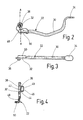
- the folder mechanism shown in the drawing exists essentially from a base plate 10 made of sheet metal, two at a distance from each other perpendicularly over the base plate protruding alignment pins 12, one by means of a Bearing web 14 on bearing tabs 16 of the base plate 10 a swivel axis fixed to the base plate between an open position and a closed position limited swiveling Folding bracket 18, one clamped on the base plate 10, against a crank 26 of the folding bracket under Prestressing spring acting in the direction of the open position 24 and one on a base plate-fixed end shield 20 pivoted, from above against the crank 26 of the folding bracket 18 with a hold-down device 28 acting actuating lever 22.
- the actuating lever 22 is made of a cut round wire 30 manufactured, the at its bearing end to form a bearing part 32 and on its handle side End stamped flat to form a handle part 34 is.
- On the flat embossed bearing part 32 is one on the a broad side protruding from the material of the bearing part extruded hollow rivet stub 36 formed, while at the opposite of the tubular rivet stub Broad side of the bearing part 32 one to the hollow rivet stub facing conical recess 38 is formed.
- the deepening 38 and the cavity 40 of the hollow rivet stub separated from each other by an intermediate floor 42.
- the Material of the hollow rivet stub 36 is used in the extrusion process predominantly from the area of the intermediate floor 42 repressed.
- the wall thickness of the intermediate floor 42 significantly smaller than that of the surrounding the rivet stub Area of the bearing part 32. From Fig. 4 it can be seen that the wall thickness of the intermediate floor is about that Corresponds to 0.2 times the wall thickness of the bearing part. Further can be seen from Fig. 4 that the hollow rivet stub an approximately cylindrical outer surface 44 and one of the intermediate floor 42 conically expanded inner surface 46 has.
- the wall thickness of the tubular rivet stub takes from the mezzanine in the embodiment shown towards its free end by at least 70%. This shape of the hollow rivet stub facilitates the flanging during the assembly process.
- the bearing part 32 of the actuating lever also has one edge portion 48 somewhat reduced in wall thickness one by 90 ° after the hollow rivet stub 36 Broadside bent foot portion 50, which for Inclusion of a slide shoe forming the hold-down member 28 is made of plastic.
- the invention relates to an operating lever for a folder mechanism and a process for its production.
- the Operating lever consists of a round wire 30 with a at its one end on the bearing side bent in a hook shape, flat stamped bearing part 32.
- On the flat stamped Bearing part 32 is a protruding on one broad side, more extruded from the material of the bearing part Hollow rivet stub 36 formed on the Hollow rivet stub opposite broad side of the bearing part a recess 38 facing the rivet stub is molded.
- the recess 38 and the cavity 40 of the Hollow rivet stubs 36 are through an intermediate floor 42 separated from each other, whose wall thickness is smaller than that of the rest of the stock.
- the bearing part 32 an edge section with a 90 ° after the hollow rivet stub 36 opposite broadside bent Foot part 50 on.
Landscapes
- Footwear And Its Accessory, Manufacturing Method And Apparatuses (AREA)
- Sheet Holders (AREA)
- Mechanical Control Devices (AREA)
- Mechanically-Actuated Valves (AREA)
Description
- Fig. 1a
- bis c eine Seitenansicht, eine Stirnseitenansicht und eine Draufsicht einer Ordnermechanik mit einem aus einem Runddraht hergestellten Betätigungshebel;
- Fig. 2
- eine Seitenansicht des Betätigungshebels der Ordnermechanik;
- Fig. 3
- eine Draufsicht auf den Betätigungshebel;
- Fig. 4
- einen Schnitt entlang der Schnittlinie A-A der Fig. 2.
Claims (16)
- Verfahren zur Herstellung eines Betätigungshebels (22) für eine Ordnermechanik, bei welchem ein abgelängter Runddraht (30) an seinem einen, lagerseitigen Ende hakenförmig gebogen, unter Bildung eines Lagerteils (32) flachgeprägt und mit einem Lagerniet (36) sowie einem Niederhalteorgan (28) versehen wird, dadurch gekennzeichnet, daß aus dem Material des Lagerteils (32) während oder nach dem Flachprägevorgang im Fließpreßverfahren ein einseitig über eine der Breitseiten überstehender Hohlnietstummel (36) geformt wird, der unter Bildung des Lagerniets umgebördelt wird.
- Verfahren nach Anspruch 1, dadurch gekennzeichnet, daß das Material des Lagerteils (32) beim Fließpreßvorgang von der dem Hohlnietstummel (36) gegenüberliegenden Breitseite aus unter Bildung einer Vertiefung (38) in Richtung Hohlnietstummel verdrängt wird.
- Verfahren nach Anspruch 2, dadurch gekennzeichnet, daß zwischen der Vertiefung (38) auf der einen Breitseite des Lagerteils (32) und dem Hohlraum (40) des Hohlnietstummels (36) ein Zwischenboden (42) gebildet wird, dessen Wandstärke kleiner als die des den Hohlnietstummel umgebenden Bereichs des flachgeprägten Lagerteils (32) ist.
- Verfahren nach einem der Ansprüche 1 bis 3, dadurch gekennzeichnet, daß das flach geprägte Lagerteil (32) in einer vorzugsweise frei gestanzten Randpartie (48) unter Bildung eines Fußteils (50) um 90° nach der dem Hohlnietstummel (36) gegenüberliegenden Breitseite umgebogen wird.
- Verfahren nach Anspruch 4, dadurch gekennzeichnet, daß die Randpartie (48) vor dem Biegevorgang unter Wandstärkenverminderung geprägt oder gepreßt wird.
- Verfahren nach Anspruch 4 oder 5, dadurch gekennzeichnet, daß das Fußteil (50) unter Bildung des Niederhalteorgans (28) mit einem Gleitschuh aus Kunststoff bestückt wird.
- Betätigungshebel für eine Ordnermechanik, der aus einem Runddraht (30) mit einem an seinem einen, lagerseitigen Ende hakenförmig gebogenen, flachgeprägten Lagerteil (32) besteht, wobei das Lagerteil mit einem Lagerniet an einem Lagerschild (20) der Ordnermechanik anlenkbar und mit einem Niederhalteorgan (28) auf einem gekröpften, federunterstützten Steg eines Umlegebügels (18) der Ordnermechanik abstützbar ist, dadurch gekennzeichnet, daß an dem flachgeprägten Lagerteil (32) ein auf der einen Breitseite überstehender, aus dem Material des Lagerteils heraus fließgepreßter Hohlnietstummel (36) angeformt ist, daß an der dem Hohlnietstummel (36) gegenüberliegenden Breitseite des Lagerteils eine zum Hohlnietstummel weisende Vertiefung (38) eingeformt ist, und daß die Vertiefung (38) und der Hohlraum (40) des Hohlnietstummels (36) durch einen Zwischenboden (42) getrennt sind, dessen Wandstärke kleiner als die des den Hohlnietstummel (36) umgebenden Bereichs des flachgeprägten Lagerteils (32) ist.
- Betätigungshebel nach Anspruch 7, dadurch gekennzeichnet, daß die Wandstärke des beim Fließpreßvorgang gebildeten Zwischenbodens (42) weniger als das 0,5-fache, vorzugsweise weniger als das 0,25-fache der Wandstärke des den Hohlnietstummel (36) umgebenden Bereichs des flachgeprägten Lagerteils (32) beträgt.
- Betätigungshebel nach Anspruch 7 oder 8, dadurch gekennzeichnet, daß der Hohlnietstummel (36) durch eine Lagerbohrung des Lagerschilds (20) der Ordnermechanik hindurchsteckbar und radial nach außen umbördelbar ist.
- Betätigungshebel nach einem der Ansprüche 7 bis 9, dadurch gekennzeichnet, daß der Hohlnietstummel (36) eine im wesentlichen zylindrische Außenfläche (44) und eine vom Zwischenboden (42) nach außen konisch erweiterte Innenfläche (46) aufweist.
- Betätigungshebel nach Anspruch 10, dadurch gekennzeichnet, daß die Wandstärke des Hohlnietstummels (36) vom Zwischenboden (42) zu seinem freien Ende hin um mindestens 50 %, vorzugsweise um mindestens 70 % abnimmt.
- Betätigungshebel nach einem der Ansprüche 7 bis 11, dadurch gekennzeichnet, daß die Vertiefung (38) eine zum Zwischenboden (42) hin konvergierende konische Wandfläche aufweist.
- Betätigungshebel nach einem der Ansprüche 7 bis 12, dadurch gekennzeichnet, daß das Lagerteil (32) eine Randpartie mit einem um etwa 90° nach der dem Hohlnietstummel (36) gegenüberliegenden Breitseite umgebogenen Fußteil (50) aufweist.
- Betätigungshebel nach Anspruch 13, dadurch gekennzeichnet, daß die das Fußteil (50) aufweisende Randpartie (48) eine kleinere Wandstärke als der den Hohlnietstummel (36) tragende Lagerteilbereich aufweist.
- Betätigungshebel nach Anspruch 13 oder 14, dadurch gekennzeichnet, daß das Fußteil (50) unter Bildung des Niederhalteorgans (28) mit einem Gleitschuh bestückt ist.
- Ordnermechanik mit einem Lagerschild (20), einem eine federunterstützte Bügelkröpfung (26) aufweisenden Umlegebügel (18) und einem Betätigungshebel (22) nach einem der Ansprüche 7 bis 15, wobei der Hohlnietstummel (36) des Betätigungshebels (22) durch eine Lagerbohrung des Lagerschilds (20) hindurchgesteckt und dort unter Bildung eines Lagerniets umgebördelt ist, und wobei das mit einem Gleitschuh bestückte Fußteil (50) des Betätigungshebels (22) unter Bildung eines Niederhalteorgans (28) auf der Bügelkröpfung (26) abgestützt ist.
Applications Claiming Priority (3)
| Application Number | Priority Date | Filing Date | Title |
|---|---|---|---|
| DE19851609A DE19851609A1 (de) | 1998-11-10 | 1998-11-10 | Betätigungshebel für eine Ordnermechanik sowie Verfahren zu dessen Herstellung |
| DE19851609 | 1998-11-10 | ||
| PCT/EP1999/007726 WO2000027649A1 (de) | 1998-11-10 | 1999-10-14 | Betätigungshebel für eine ordnermechanik sowie verfahren zu dessen herstellung |
Publications (2)
| Publication Number | Publication Date |
|---|---|
| EP1128967A1 EP1128967A1 (de) | 2001-09-05 |
| EP1128967B1 true EP1128967B1 (de) | 2003-02-12 |
Family
ID=7887174
Family Applications (1)
| Application Number | Title | Priority Date | Filing Date |
|---|---|---|---|
| EP99950722A Expired - Lifetime EP1128967B1 (de) | 1998-11-10 | 1999-10-14 | Betätigungshebel für eine ordnermechanik sowie verfahren zu dessen herstellung |
Country Status (5)
| Country | Link |
|---|---|
| EP (1) | EP1128967B1 (de) |
| AT (1) | ATE232475T1 (de) |
| DE (2) | DE19851609A1 (de) |
| TR (1) | TR200101284T2 (de) |
| WO (1) | WO2000027649A1 (de) |
Families Citing this family (1)
| Publication number | Priority date | Publication date | Assignee | Title |
|---|---|---|---|---|
| DE20306130U1 (de) | 2003-04-17 | 2003-07-03 | Lunz, Elke, 96047 Bamberg | Aktenordner mit verbesserter Öffnungs-/Schließmechanik |
Family Cites Families (2)
| Publication number | Priority date | Publication date | Assignee | Title |
|---|---|---|---|---|
| FR2672244B1 (fr) * | 1991-02-04 | 1995-02-03 | Hertschuh A Mecarex Sa | Levier de mecanisme de fermeture pour classeur. |
| DE4428113A1 (de) * | 1994-08-09 | 1996-02-15 | Leitz Louis Kg | Ordnermechanik |
-
1998
- 1998-11-10 DE DE19851609A patent/DE19851609A1/de not_active Withdrawn
-
1999
- 1999-10-14 AT AT99950722T patent/ATE232475T1/de active
- 1999-10-14 DE DE59904293T patent/DE59904293D1/de not_active Expired - Lifetime
- 1999-10-14 TR TR2001/01284T patent/TR200101284T2/xx unknown
- 1999-10-14 WO PCT/EP1999/007726 patent/WO2000027649A1/de not_active Ceased
- 1999-10-14 EP EP99950722A patent/EP1128967B1/de not_active Expired - Lifetime
Also Published As
| Publication number | Publication date |
|---|---|
| WO2000027649A1 (de) | 2000-05-18 |
| TR200101284T2 (tr) | 2002-01-21 |
| DE19851609A1 (de) | 2000-05-11 |
| EP1128967A1 (de) | 2001-09-05 |
| DE59904293D1 (de) | 2003-03-20 |
| ATE232475T1 (de) | 2003-02-15 |
Similar Documents
| Publication | Publication Date | Title |
|---|---|---|
| CH634131A5 (de) | Klammer aus kunststoff. | |
| DE2810844A1 (de) | Buegelmechanik fuer loseblatt-ordner | |
| AT409650B (de) | Türflügel-anschlagteil für möbelscharniere | |
| EP1596689A1 (de) | Griffleiste für eine schublade, insbesondere für eine schublade von lager- und betriebsmitteleinrichtungen | |
| DE29920171U1 (de) | Zange mit wenigstens zwei Gelenkeinstellungen | |
| DE3238898C1 (de) | Entklammerungszange | |
| AT392236B (de) | Verschlussmechanik | |
| DE19750206A1 (de) | Spanlos geformter Schlepphebel | |
| DE3230312A1 (de) | Locher fuer papier- und pappwaren aus im wesentlichen zweistrangpress- bzw. extrusionsprofilen | |
| EP1128967A1 (de) | Betätigungshebel für eine ordnermechanik sowie verfahren zu dessen herstellung | |
| EP0649361B1 (de) | Heftklammergerät | |
| DE8218793U1 (de) | Aufreihvorrichtung fuer briefordner oder dgl. | |
| EP0520188B1 (de) | Ordnermechanik | |
| WO1993011978A1 (de) | Wischarm, insbesondere zur reinigung von scheiben an kraftfahrzeugen | |
| DE10246448B4 (de) | Ordnermechanik | |
| AT404699B (de) | Verschlussmechanik | |
| WO1996005071A1 (de) | Ordnermechanik | |
| DE3026270C2 (de) | Scharnier | |
| DE10332764B3 (de) | Form zum Zubereiten oder Backen von Teigwaren, insbesondere Torten- oder Backring | |
| DE19640119C2 (de) | Biegewerkzeug | |
| DE102006057358B4 (de) | Gelenkanordnung mit einer Clipsverbindung | |
| EP0520189A1 (de) | Ordnermechanik | |
| DE3326479A1 (de) | Brieflocher | |
| AT500933B1 (de) | Verschlussmechanik für gelochte, lose blätter | |
| EP1365092A2 (de) | Schiebeverschluss für eine schwenkbare Abdeckklappe |
Legal Events
| Date | Code | Title | Description |
|---|---|---|---|
| PUAI | Public reference made under article 153(3) epc to a published international application that has entered the european phase |
Free format text: ORIGINAL CODE: 0009012 |
|
| 17P | Request for examination filed |
Effective date: 20010320 |
|
| AK | Designated contracting states |
Kind code of ref document: A1 Designated state(s): AT BE CH CY DE DK ES FI FR GB GR IE IT LI LU MC NL PT SE |
|
| GRAG | Despatch of communication of intention to grant |
Free format text: ORIGINAL CODE: EPIDOS AGRA |
|
| 17Q | First examination report despatched |
Effective date: 20020122 |
|
| RIN1 | Information on inventor provided before grant (corrected) |
Inventor name: GOLDERER, ALEXANDER Inventor name: FROEMEL, FRANZ |
|
| GRAG | Despatch of communication of intention to grant |
Free format text: ORIGINAL CODE: EPIDOS AGRA |
|
| GRAG | Despatch of communication of intention to grant |
Free format text: ORIGINAL CODE: EPIDOS AGRA |
|
| GRAH | Despatch of communication of intention to grant a patent |
Free format text: ORIGINAL CODE: EPIDOS IGRA |
|
| GRAH | Despatch of communication of intention to grant a patent |
Free format text: ORIGINAL CODE: EPIDOS IGRA |
|
| GRAA | (expected) grant |
Free format text: ORIGINAL CODE: 0009210 |
|
| AK | Designated contracting states |
Designated state(s): AT BE CH CY DE DK ES FI FR GB GR IE IT LI LU MC NL PT SE |
|
| PG25 | Lapsed in a contracting state [announced via postgrant information from national office to epo] |
Ref country code: NL Free format text: LAPSE BECAUSE OF FAILURE TO SUBMIT A TRANSLATION OF THE DESCRIPTION OR TO PAY THE FEE WITHIN THE PRESCRIBED TIME-LIMIT Effective date: 20030212 Ref country code: IT Free format text: LAPSE BECAUSE OF FAILURE TO SUBMIT A TRANSLATION OF THE DESCRIPTION OR TO PAY THE FEE WITHIN THE PRE;WARNING: LAPSES OF ITALIAN PATENTS WITH EFFECTIVE DATE BEFORE 2007 MAY HAVE OCCURRED AT ANY TIME BEFORE 2007. THE CORRECT EFFECTIVE DATE MAY BE DIFFERENT FROM THE ONE RECORDED.SCRIBED TIME-LIMIT Effective date: 20030212 Ref country code: IE Free format text: LAPSE BECAUSE OF FAILURE TO SUBMIT A TRANSLATION OF THE DESCRIPTION OR TO PAY THE FEE WITHIN THE PRESCRIBED TIME-LIMIT Effective date: 20030212 Ref country code: GR Free format text: LAPSE BECAUSE OF FAILURE TO SUBMIT A TRANSLATION OF THE DESCRIPTION OR TO PAY THE FEE WITHIN THE PRESCRIBED TIME-LIMIT Effective date: 20030212 Ref country code: GB Free format text: LAPSE BECAUSE OF FAILURE TO SUBMIT A TRANSLATION OF THE DESCRIPTION OR TO PAY THE FEE WITHIN THE PRESCRIBED TIME-LIMIT Effective date: 20030212 Ref country code: FR Free format text: LAPSE BECAUSE OF FAILURE TO SUBMIT A TRANSLATION OF THE DESCRIPTION OR TO PAY THE FEE WITHIN THE PRESCRIBED TIME-LIMIT Effective date: 20030212 Ref country code: FI Free format text: LAPSE BECAUSE OF FAILURE TO SUBMIT A TRANSLATION OF THE DESCRIPTION OR TO PAY THE FEE WITHIN THE PRESCRIBED TIME-LIMIT Effective date: 20030212 |
|
| REG | Reference to a national code |
Ref country code: GB Ref legal event code: FG4D Free format text: NOT ENGLISH |
|
| REG | Reference to a national code |
Ref country code: CH Ref legal event code: EP |
|
| REG | Reference to a national code |
Ref country code: GB Ref legal event code: 732E |
|
| REF | Corresponds to: |
Ref document number: 59904293 Country of ref document: DE Date of ref document: 20030320 Kind code of ref document: P |
|
| 111Z | Information provided on other rights and legal means of execution |
Free format text: ATBECHCYDEDKESFIFRGBGRIEITLILUMCNLPTSE Effective date: 20030211 |
|
| PG25 | Lapsed in a contracting state [announced via postgrant information from national office to epo] |
Ref country code: SE Free format text: LAPSE BECAUSE OF FAILURE TO SUBMIT A TRANSLATION OF THE DESCRIPTION OR TO PAY THE FEE WITHIN THE PRESCRIBED TIME-LIMIT Effective date: 20030512 Ref country code: PT Free format text: LAPSE BECAUSE OF FAILURE TO SUBMIT A TRANSLATION OF THE DESCRIPTION OR TO PAY THE FEE WITHIN THE PRESCRIBED TIME-LIMIT Effective date: 20030512 Ref country code: DK Free format text: LAPSE BECAUSE OF FAILURE TO SUBMIT A TRANSLATION OF THE DESCRIPTION OR TO PAY THE FEE WITHIN THE PRESCRIBED TIME-LIMIT Effective date: 20030512 |
|
| NLV1 | Nl: lapsed or annulled due to failure to fulfill the requirements of art. 29p and 29m of the patents act | ||
| GBV | Gb: ep patent (uk) treated as always having been void in accordance with gb section 77(7)/1977 [no translation filed] |
Effective date: 20030212 |
|
| PG25 | Lapsed in a contracting state [announced via postgrant information from national office to epo] |
Ref country code: ES Free format text: LAPSE BECAUSE OF FAILURE TO SUBMIT A TRANSLATION OF THE DESCRIPTION OR TO PAY THE FEE WITHIN THE PRESCRIBED TIME-LIMIT Effective date: 20030828 |
|
| REG | Reference to a national code |
Ref country code: IE Ref legal event code: FD4D Ref document number: 1128967E Country of ref document: IE |
|
| PG25 | Lapsed in a contracting state [announced via postgrant information from national office to epo] |
Ref country code: LU Free format text: LAPSE BECAUSE OF NON-PAYMENT OF DUE FEES Effective date: 20031014 Ref country code: CY Free format text: LAPSE BECAUSE OF FAILURE TO SUBMIT A TRANSLATION OF THE DESCRIPTION OR TO PAY THE FEE WITHIN THE PRESCRIBED TIME-LIMIT Effective date: 20031014 |
|
| PG25 | Lapsed in a contracting state [announced via postgrant information from national office to epo] |
Ref country code: MC Free format text: LAPSE BECAUSE OF NON-PAYMENT OF DUE FEES Effective date: 20031031 Ref country code: BE Free format text: LAPSE BECAUSE OF NON-PAYMENT OF DUE FEES Effective date: 20031031 |
|
| PLBE | No opposition filed within time limit |
Free format text: ORIGINAL CODE: 0009261 |
|
| STAA | Information on the status of an ep patent application or granted ep patent |
Free format text: STATUS: NO OPPOSITION FILED WITHIN TIME LIMIT |
|
| EN | Fr: translation not filed | ||
| 26N | No opposition filed |
Effective date: 20031113 |
|
| BERE | Be: lapsed |
Owner name: *ESSELTE LEITZ G.M.B.H. & CO. K.G. Effective date: 20031031 |
|
| PGFP | Annual fee paid to national office [announced via postgrant information from national office to epo] |
Ref country code: AT Payment date: 20101014 Year of fee payment: 12 |
|
| REG | Reference to a national code |
Ref country code: AT Ref legal event code: MM01 Ref document number: 232475 Country of ref document: AT Kind code of ref document: T Effective date: 20111014 |
|
| PG25 | Lapsed in a contracting state [announced via postgrant information from national office to epo] |
Ref country code: AT Free format text: LAPSE BECAUSE OF NON-PAYMENT OF DUE FEES Effective date: 20111014 |
|
| PGFP | Annual fee paid to national office [announced via postgrant information from national office to epo] |
Ref country code: CH Payment date: 20141021 Year of fee payment: 16 |
|
| REG | Reference to a national code |
Ref country code: DE Ref legal event code: R082 Ref document number: 59904293 Country of ref document: DE Representative=s name: PATENTANWAELTE BREGENZER UND REULE PARTNERSCHA, DE |
|
| PGFP | Annual fee paid to national office [announced via postgrant information from national office to epo] |
Ref country code: DE Payment date: 20150912 Year of fee payment: 17 |
|
| REG | Reference to a national code |
Ref country code: CH Ref legal event code: PL |
|
| PG25 | Lapsed in a contracting state [announced via postgrant information from national office to epo] |
Ref country code: CH Free format text: LAPSE BECAUSE OF NON-PAYMENT OF DUE FEES Effective date: 20151031 Ref country code: LI Free format text: LAPSE BECAUSE OF NON-PAYMENT OF DUE FEES Effective date: 20151031 |
|
| REG | Reference to a national code |
Ref country code: DE Ref legal event code: R119 Ref document number: 59904293 Country of ref document: DE |
|
| PG25 | Lapsed in a contracting state [announced via postgrant information from national office to epo] |
Ref country code: DE Free format text: LAPSE BECAUSE OF NON-PAYMENT OF DUE FEES Effective date: 20170503 |