EP1127677B1 - Vorrichtung zum Verformen von thermoplastischen Materialien - Google Patents
Vorrichtung zum Verformen von thermoplastischen Materialien Download PDFInfo
- Publication number
- EP1127677B1 EP1127677B1 EP01103880A EP01103880A EP1127677B1 EP 1127677 B1 EP1127677 B1 EP 1127677B1 EP 01103880 A EP01103880 A EP 01103880A EP 01103880 A EP01103880 A EP 01103880A EP 1127677 B1 EP1127677 B1 EP 1127677B1
- Authority
- EP
- European Patent Office
- Prior art keywords
- seal
- turntable
- wall
- supporting device
- box
- Prior art date
- Legal status (The legal status is an assumption and is not a legal conclusion. Google has not performed a legal analysis and makes no representation as to the accuracy of the status listed.)
- Expired - Lifetime
Links
- 239000012815 thermoplastic material Substances 0.000 title claims description 6
- 238000007493 shaping process Methods 0.000 title claims 2
- 238000000465 moulding Methods 0.000 claims description 13
- 238000007373 indentation Methods 0.000 claims description 9
- 238000010030 laminating Methods 0.000 claims description 5
- 238000007664 blowing Methods 0.000 claims 7
- KRTSDMXIXPKRQR-AATRIKPKSA-N monocrotophos Chemical compound CNC(=O)\C=C(/C)OP(=O)(OC)OC KRTSDMXIXPKRQR-AATRIKPKSA-N 0.000 claims 1
- 238000011017 operating method Methods 0.000 claims 1
- 238000005192 partition Methods 0.000 description 21
- 238000000034 method Methods 0.000 description 5
- 238000004080 punching Methods 0.000 description 2
- 238000007789 sealing Methods 0.000 description 2
- 238000006073 displacement reaction Methods 0.000 description 1
- 239000004744 fabric Substances 0.000 description 1
- 238000003780 insertion Methods 0.000 description 1
- 230000037431 insertion Effects 0.000 description 1
- 239000000463 material Substances 0.000 description 1
- 230000004048 modification Effects 0.000 description 1
- 238000012986 modification Methods 0.000 description 1
- 238000003825 pressing Methods 0.000 description 1
Images



Classifications
-
- B—PERFORMING OPERATIONS; TRANSPORTING
- B29—WORKING OF PLASTICS; WORKING OF SUBSTANCES IN A PLASTIC STATE IN GENERAL
- B29C—SHAPING OR JOINING OF PLASTICS; SHAPING OF MATERIAL IN A PLASTIC STATE, NOT OTHERWISE PROVIDED FOR; AFTER-TREATMENT OF THE SHAPED PRODUCTS, e.g. REPAIRING
- B29C51/00—Shaping by thermoforming, i.e. shaping sheets or sheet like preforms after heating, e.g. shaping sheets in matched moulds or by deep-drawing; Apparatus therefor
- B29C51/26—Component parts, details or accessories; Auxiliary operations
-
- B—PERFORMING OPERATIONS; TRANSPORTING
- B29—WORKING OF PLASTICS; WORKING OF SUBSTANCES IN A PLASTIC STATE IN GENERAL
- B29C—SHAPING OR JOINING OF PLASTICS; SHAPING OF MATERIAL IN A PLASTIC STATE, NOT OTHERWISE PROVIDED FOR; AFTER-TREATMENT OF THE SHAPED PRODUCTS, e.g. REPAIRING
- B29C31/00—Handling, e.g. feeding of the material to be shaped, storage of plastics material before moulding; Automation, i.e. automated handling lines in plastics processing plants, e.g. using manipulators or robots
- B29C31/006—Handling moulds, e.g. between a mould store and a moulding machine
-
- B—PERFORMING OPERATIONS; TRANSPORTING
- B29—WORKING OF PLASTICS; WORKING OF SUBSTANCES IN A PLASTIC STATE IN GENERAL
- B29C—SHAPING OR JOINING OF PLASTICS; SHAPING OF MATERIAL IN A PLASTIC STATE, NOT OTHERWISE PROVIDED FOR; AFTER-TREATMENT OF THE SHAPED PRODUCTS, e.g. REPAIRING
- B29C51/00—Shaping by thermoforming, i.e. shaping sheets or sheet like preforms after heating, e.g. shaping sheets in matched moulds or by deep-drawing; Apparatus therefor
- B29C51/26—Component parts, details or accessories; Auxiliary operations
- B29C51/30—Moulds
- B29C51/303—Moulds with sealing means or the like
-
- B—PERFORMING OPERATIONS; TRANSPORTING
- B29—WORKING OF PLASTICS; WORKING OF SUBSTANCES IN A PLASTIC STATE IN GENERAL
- B29C—SHAPING OR JOINING OF PLASTICS; SHAPING OF MATERIAL IN A PLASTIC STATE, NOT OTHERWISE PROVIDED FOR; AFTER-TREATMENT OF THE SHAPED PRODUCTS, e.g. REPAIRING
- B29C51/00—Shaping by thermoforming, i.e. shaping sheets or sheet like preforms after heating, e.g. shaping sheets in matched moulds or by deep-drawing; Apparatus therefor
- B29C51/16—Lining or labelling
- B29C51/162—Lining or labelling of deep containers or boxes
-
- B—PERFORMING OPERATIONS; TRANSPORTING
- B29—WORKING OF PLASTICS; WORKING OF SUBSTANCES IN A PLASTIC STATE IN GENERAL
- B29C—SHAPING OR JOINING OF PLASTICS; SHAPING OF MATERIAL IN A PLASTIC STATE, NOT OTHERWISE PROVIDED FOR; AFTER-TREATMENT OF THE SHAPED PRODUCTS, e.g. REPAIRING
- B29C51/00—Shaping by thermoforming, i.e. shaping sheets or sheet like preforms after heating, e.g. shaping sheets in matched moulds or by deep-drawing; Apparatus therefor
- B29C51/18—Thermoforming apparatus
- B29C51/20—Thermoforming apparatus having movable moulds or mould parts
- B29C51/22—Thermoforming apparatus having movable moulds or mould parts rotatable about an axis
Definitions
- the invention relates to a device for Deformation of thermoplastic materials or for Laminating support members
- a device for Deformation of thermoplastic materials or for Laminating support members comprising at least one portable carrying device for a lower tool or a molded part receptacle and at least one portable Carrying device for an upper tool and one against the Atmosphere sealable box for holding a Carrying device with lower tool or molding reception during a work process, being used for the transport of at least one support means a turntable is provided which has a receiving space for each carrying device, and wherein the receiving space of the respectively adjacent Recording place is separated by a partition and the one Closes the opening in the box except for a small gap, if a carrying device in the provided in the box Workstation is located below an upper tool.
- the object of the invention is to provide a device of the initially explained way to design that with ease of use the device, short cycle times and at a virtually unlimited molding height a faster Tool change is possible.
- a significant advantage of this embodiment of the invention is that after retracting a tool or a support member in the Vorblaskasten this through the partition and the associated gasket in the shortest possible time Time after reaching the working position of the tool or support member in the Vorblaskasten, sealed and therefore is operational, and that the outside of the pre-blow box remaining space immediately with a new carrier part can be occupied.
- Opposite a device with Sliding table has the advantage that at the same cycle time the time remaining for the insertion of the carrier part, is much longer in the embodiment according to the invention as in the known Schiebetischausesthesia operation, because at the Arrangement of sliding tables it is necessary to appropriate To bring closing flaps to the closed position seal the Vorblaskasten.
- the core of the invention is the arrangement a partition in conjunction with a seal, the one recording place of neighboring recording places separates, said partition wall, the passage opening for a Closes lower tool or a carrier part in the Vorblaskasten, so that in the Vorblaskasten both a negative pressure as also an overpressure according to the intended method of operation can be built.
- carrying device is For example, a base plate for a mold or a Meant carrier part.
- the seal is on the stationary Vorblaskastenwand arranged and pressed against the partition wall.
- the seal can also be arranged on the partition wall and be pressed against the fixed Vorblaskasten.
- a particularly preferred embodiment of the invention in that the seal is designed as an elastic seal and in a groove of the Vorblaskastenwand along the Opening edge is arranged and that the seal through a pressure medium can be pressed against the dividing wall.
- the Arrangement of the seal in the fixed wall of the Vorblaskastens has the advantage of fixed arrangement of supply lines for the pressure medium to the seal against to push the partition. If the seal is elastic Enough educated, it pulls itself by itself the elasticity back to the initial state, so that when turning the turntable, the seal no friction effect subject.
- the seal can be advantageous to strengthen the turning process of the turntable be when the seal after switching off the pressure medium is subjected to a restoring force.
- This can for example be generated by the fact that the seal Negative pressure can be acted upon.
- the basis the groove, in which an elastic seal is guided, to a Vacuum source can be connected, causing the seal stronger and faster in the groove is withdrawn and from the partition, freeing them from rotation not obstructed and also no wear by turning the turntable is subjected.
- the seal can use the turning earlier, which a shorter cycle time.
- a particularly simple embodiment results when the Seal is designed as a hose seal and the Hose interior to a pressure source and / or a vacuum source is connectable.
- a structurally simple embodiment of the turntable and Its sealing results in an advantageous manner that the turntable at the bottom has a pivot bearing and a Rotary drive has that facing the pivot bearing Wall of the pre-blow box forming a dome around the Swivel bearing and the rotary drive is guided around and that the Partition in the area of the indentation on both sides has a flange that covers this indentation, the with the seal arranged on the wall of the preblow box interacts.
- the turntable at each pickup place two for recording a support device for a lower tool or a Carrier part serving pads, which consists of a holding position for the carrying device in a passage position can be transferred, in which a tool change with lowering the carrying device is feasible.
- an additional Lifting table can then not only the lower tool, but also below the lowered to the recordings Upper tool in the working position of the turntable in picked up the workstation and thus a complete tool change complete with tenter frame change.
- a Upper tool arranged at one above the turntable be arranged upper lift table. This is it the arrangement of a single upper tool, the with, for example, two sub-tools arranged on the turntable works together in alternation.
- these can each be associated with a sliding table, which is height-adjustable.
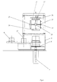
- the device for deformation of thermoplastic materials or for laminating support parts with either thermoplastic materials or with other materials, coated fabrics, for example, has a base frame 1, within which a rotary drive 2 for a Turntable 3 is arranged. On the base frame 1 is a Upper frame 4 arranged, the corresponding guides 5 an upper table 6 slidably held in the vertical direction.
- a lifting device 7 is provided below the support level of the base frame 1, ie within the bottom under the device.
- a lifting device 7 is provided for a lower lifting table 8.
- a Vorblaskasten 9 formed in its front wall 10 has an opening 11 which extends almost over the entire Front wall 10 extends between the corner posts 1.1 and 1.2, which is closed by a partition wall 12, firmly on arranged the turntable 3 and rotatable together with this is.
- the front wall 10 As in the Center of the turntable 3 of the rotary drive 2 with the corresponding Storage is provided for the table, the front wall 10 not arranged in a plane running, but this front wall 10 has a recess 20 which is indicated in Figure 3 with a dash-dotted line.
- This indentation surrounds the rotary drive so that this outside the Vorblaskastens lies.
- the seal 19 follows this Indentation, so that the opening 11 completely with a Seal is provided in a groove within the Front wall 10 is located and by means of a pressure medium this groove out and pressed against the partition 12 is.
- This seal is designed as a hose seal and is connected to a pressure source.
- this hose seal Also connectable to a vacuum source, so that They very quickly withdrew from their sealing position can be. In this withdrawn position can then the turntable will be twisted together with the dividing wall, without damaging the seal.
- the indentation 20 made a seal of the opening 11 can is at the bottom edge of the partition 12 after each Page excellently arranged a flange 21 and 22, which, like 3, the recess 20 completely covered, so that provided in this area seal 19 from below presses against the respective flange, which is located in the Area of this indentation of the front wall of the Vorblaskastens located.
- FIG. 6 shows an inflated state of FIG Front wall 10 recessed seal during the rest position the rotatable partition 12 to a seal of the Gap between the front wall 10 and the partition 12 to enable.
- the turntable 3 has on both sides of the line 23 designated symmetry axis, which also through the center of rotation goes, in each case two parallel rails 24 and 25, the equipped with swivel pads 26 and 27.
- holding position of the pads 26 and 27th serve these requirements for receiving a support device 28, i.e. a base plate, for a carrier part 15 or a lower tool, which is not shown in the drawing.
- the pads 26 and 27 allow the support to be picked up 28 to put this down together with one Lower mold and clamping frame, if the corresponding receiving space of the turntable 3 in Vorblaskasten 9 is located, so a tool change to carry out.
- a support 28 i. on a base plate located lower tool or the carrier part to be laminated 15 is after filing on the turntable 3 by turning of the turntable in the direction of arrow 29 in the Vorblaskasten 9 retracted and into the inside of the Vorblaskastens working position below the upper table 6 brought.
- the film 18 is not by means illustrated needle chains between the sub-frame 16th and the upper frame 17, whereby the collapse of the clamping frame of the Vorblaskasten 9 is sealed in the region of the opening 14 upwards.
- the seal on the front wall 10 takes place through the partition wall 12, the flange 21 and 22 and the circumferential seal 19, which presses in the inflated state against the partition and thus seals the Vorblaskasten in the region of the opening 11.
- either compressed air is used blown into the Vorblaskasten or the Vorblaskasten is subjected to a slight vacuum.
- the already previously heated film 18 either up in the direction of the upper table 6 bulged or sucked down into the Vorblaskasten.
- the support device 28 with the lower tool or a support member 15th pushed up against the film 18 and the film is in this condition by means of connectable to the support device Vacuum against the support member 15 or a corresponding Lower tool sucked and deformed.
- the upper table 6 can a corresponding to the lower tool or the support part 15 trained upper tool can be provided or it can Form aids are provided, the most critical Make the pressing of the film to the lower tool or cause the support member 15.
- the upper table 6 movable in height.
- Figure 4 shows a modified embodiment, wherein the modification it consists in that at a vertically displaceable Upper table 30 a holding device for a turnstile 31, or a rotatable tool receiving device, e.g. in Form of a square frame, is provided by means of a drive 32 about an axis 33 can be driven.
- the Turnstile has four arms, at the ends of different Tools 34 to 37 are arranged. These different ones Each tool is a mold assist tool, e.g. a Vorblas- or Vorsaugschale, a punching tool or a rigid or driven molding aid, as needed with the to be produced molding, which is located on the lower tool or carrier part is engaged.
Landscapes
- Engineering & Computer Science (AREA)
- Mechanical Engineering (AREA)
- Robotics (AREA)
- Blow-Moulding Or Thermoforming Of Plastics Or The Like (AREA)
- Casting Or Compression Moulding Of Plastics Or The Like (AREA)
- Moulds For Moulding Plastics Or The Like (AREA)
Description
- Figur 1:
- eine Vorderansicht einer Vorrichtung zum Verformen von thermoplastischen Materialen oder Kaschieren von Trägerteilen;
- Figur 2:
- eine Seitenansicht der Vorrichtung nach Figur 1;
- Figur 3:
- einen Schnitt nach der Linie III-III in Figur 1;
- Figur 4:
- eine der Figur 2 entsprechende Seitenansicht einer Vorrichtung in geänderter Ausgestaltung; und
- Figuren 5 und 6:
- eine Einzelheit des in Figur 2 mit V und VI bezeichneten Bereiches in vergrößerter Darstellung in zwei unterschiedlichen Betriebsstellungen.
Claims (13)
- Vorrichtung zum Verformen von thermoplastischen Materialien oder zum Kaschieren von Trägerteilen, umfassend mindestens eine ortsbewegliche Trageinrichtung für ein Unterwerkzeug oder eine Formteilaufnahme und mindestens eine ortsbewegliche Trageinrichtung für ein Oberwerkzeug sowie einen gegen die Atmosphäre abdichtbaren Kasten zur Aufnahme einer Trageinrichtung mit Unterwerkzeug oder Formteilaufnahme während eines Arbeitsvorganges, wobei für den Transport der zumindest einen Trageinrichtung (28) ein Drehtisch (3) vorgesehen ist, der für jede Trageinrichtung (28) einen Aufnahmeplatz aufweist, und wobei jeder Aufnahmeplatz von dem jeweils benachbarten Aufnahmeplatz durch eine Trennwand (12) getrennt ist und die eine Öffnung (11) im Kasten (9) bis auf einen geringen Spalt verschließt, wenn sich eine Trageinrichtung in der im Kasten vorgesehenen Arbeitsstation unterhalb eines Oberwerkzeuges befindet, dadurch gekennzeichnet, dass der Kasten ein Vorblaskasten ist, und dass der geringe Spalt zwischen der Trennwand (12) und der Vorblaskastenwand (10) durch eine Dichtung (19) abdichtbar ist.
- Vorrichtung nach Anspruch 1, wobei die Dichtung (19) an der ortsfesten Vorblaskastenwand (10) angeordnet und gegen die Trennwand (12) andrückbar ist.
- Vorrichtung nach Anspruch 1, wobei die Dichtung (19) an der Trennwand (12) angeordnet und gegen den ortsfesten Vorblaskasten (9) andrückbar ist.
- Vorrichtung nach einem der Ansprüche 1 bis 3, wobei die Dichtung (19) als elastische Dichtung ausgebildet und in einer Nut der Vorblaskastenwand (10) entlang des Öffnungsrandes angeordnet ist, und dass die Dichtung (19) durch ein Druckmedium gegen die Trennwand (12) andrückbar ist.
- Vorrichtung nach Anspruch 4, wobei die Dichtung (19) nach Abschalten des Druckmediums einer Rückstellkraft unterworfen ist.
- Vorrichtung nach Anspruch 4 oder 5, wobei die Dichtung (19) durch Unterdruck beaufschlagbar ist.
- Vorrichtung nach einem der Ansprüche 1 bis 6, wobei die Dichtung (19) als Schlauchdichtung ausgebildet ist und das Schlauchinnere an eine Druckquelle und/oder eine Unterdruckquelle anschließbar ist.
- Vorrichtung nach einem der Ansprüche 1 bis 7, wobei der Drehtisch (3) an der Unterseite ein Drehlager und einen Drehantrieb (2) aufweist, dass die dem Drehlager zugewandte Wand (10) des Vorblaskastens (9) eine Einbuchtung (20) bildend, um das Drehlager und den Drehantrieb (2) herumgeführt ist, und dass die Trennwand (12) im Bereich der Einbuchtung (20) an ihren beiden Seiten einen diese Einbuchtung überdeckenden Flansch (21, 22) aufweist, der mit der an der Wand (10, 20) des Vorblaskastens (9) angeordneten Dichtung (19) zusammenwirkt.
- Vorrichtung nach einem der Ansprüche 1 bis 8, wobei der Drehtisch (3) an jedem Aufnahmeplatz zwei für die Aufnahme einer Trageinrichtung (28) für ein Unterwerkzeug oder ein Trägerteil (15) dienende Auflagen (26, 27) aufweist, die aus einer Haltestellung für die Trageinrichtung (28) in eine Durchlassstellung überführbar sind, in welcher ein Werkzeugwechsel mit Absenkung der Trageinrichtung (28) durchführbar ist.
- Vorrichtung nach einem der Ansprüche 1 bis 8, wobei ein Oberwerkzeug an einem oberhalb des Drehtisches (3) angeordneten Hubtisch (6) angeordnet ist.
- Vorrichtung nach einem der Ansprüche 1 bis 8, wobei bei Verwendung mehrerer Oberwerkzeuge diese jeweils einem Schiebetisch zugeordnet sind, der höhenbeweglich ist.
- Vorrichtung nach einem der Ansprüche 1 bis 8, wobei Oberwerkzeuge an einer drehbar und antreibbar gelagerten Werkzeugaufnahme (31) angeordnet sind.
- Vorrichtung nach Anspruch 12, wobei die Werkzeugaufnahme (31) höhenbeweglich ist.
Applications Claiming Priority (2)
| Application Number | Priority Date | Filing Date | Title |
|---|---|---|---|
| DE10009403 | 2000-02-28 | ||
| DE10009403A DE10009403B4 (de) | 2000-02-28 | 2000-02-28 | Vorrichtung zum Verformen von thermoplastischen Materialien |
Publications (3)
| Publication Number | Publication Date |
|---|---|
| EP1127677A2 EP1127677A2 (de) | 2001-08-29 |
| EP1127677A3 EP1127677A3 (de) | 2003-10-08 |
| EP1127677B1 true EP1127677B1 (de) | 2005-05-04 |
Family
ID=7632742
Family Applications (1)
| Application Number | Title | Priority Date | Filing Date |
|---|---|---|---|
| EP01103880A Expired - Lifetime EP1127677B1 (de) | 2000-02-28 | 2001-02-16 | Vorrichtung zum Verformen von thermoplastischen Materialien |
Country Status (4)
| Country | Link |
|---|---|
| US (1) | US6589042B2 (de) |
| EP (1) | EP1127677B1 (de) |
| DE (2) | DE10009403B4 (de) |
| ES (1) | ES2242665T3 (de) |
Families Citing this family (10)
| Publication number | Priority date | Publication date | Assignee | Title |
|---|---|---|---|---|
| AU2004100000A4 (en) | 2004-01-02 | 2004-02-12 | Sands Innovations Pty Ltd | Dispensing stirring implement |
| AU2008210267B2 (en) | 2007-01-31 | 2014-06-12 | Sands Innovations Pty Ltd | A dispensing utensil and manufacturing method therefor |
| AU2008365185B2 (en) | 2008-12-09 | 2016-05-05 | Sands Innovations Pty Ltd | A dispensing container |
| USD636890S1 (en) | 2009-09-17 | 2011-04-26 | Sands Innovations Pty. Ltd. | Dispensing utensil |
| US8511500B2 (en) | 2010-06-07 | 2013-08-20 | Sands Innovations Pty. Ltd. | Dispensing container |
| US8485360B2 (en) | 2011-03-04 | 2013-07-16 | Sands Innovations Pty, Ltd. | Fracturable container |
| FI124947B (fi) * | 2012-03-19 | 2015-04-15 | Stora Enso Oyj | Syvävedetty paperivuoka, menetelmä ja laitteisto sen valmistamiseksi, ja vuokamallinen tuotepakkaus |
| DE102012105885A1 (de) * | 2012-07-03 | 2014-01-09 | Dr. Ing. H.C. F. Porsche Aktiengesellschaft | Kaschiervorrichtung und zugehöriges Verfahren |
| EP3034269B1 (de) | 2014-12-15 | 2018-03-21 | C.M.S. S.p.A. | Thermoformvorrichtung mit einer dichtung |
| US10576680B2 (en) | 2015-11-19 | 2020-03-03 | The Boeing Company | Modular thermoforming system |
Family Cites Families (6)
| Publication number | Priority date | Publication date | Assignee | Title |
|---|---|---|---|---|
| US2547275A (en) * | 1945-12-28 | 1951-04-03 | Lyon George Albert | Method of and apparatus for making plastic wheel trim |
| US4724113A (en) * | 1985-12-16 | 1988-02-09 | The Dow Chemical Company | Method of molding using an inflatable seal |
| AU589749B2 (en) * | 1987-03-26 | 1989-10-19 | Tachi-S Co., Ltd. | Apparatus for manufacturing a seat |
| DE3929135C1 (de) * | 1989-09-01 | 1990-10-18 | Paul Kiefel Gmbh, 8228 Freilassing, De | |
| US5453000A (en) * | 1993-08-30 | 1995-09-26 | Toymax Incorporated | Toy vacuum molding apparatus |
| US6315295B1 (en) * | 1997-03-04 | 2001-11-13 | Magna International Investments (Barbados) Inc. | Inflatable seals |
-
2000
- 2000-02-28 DE DE10009403A patent/DE10009403B4/de not_active Expired - Fee Related
-
2001
- 2001-02-16 ES ES01103880T patent/ES2242665T3/es not_active Expired - Lifetime
- 2001-02-16 EP EP01103880A patent/EP1127677B1/de not_active Expired - Lifetime
- 2001-02-16 DE DE50106062T patent/DE50106062D1/de not_active Expired - Lifetime
- 2001-02-28 US US09/795,837 patent/US6589042B2/en not_active Expired - Lifetime
Also Published As
| Publication number | Publication date |
|---|---|
| DE50106062D1 (de) | 2005-06-09 |
| US20010033877A1 (en) | 2001-10-25 |
| EP1127677A3 (de) | 2003-10-08 |
| US6589042B2 (en) | 2003-07-08 |
| DE10009403B4 (de) | 2008-02-21 |
| EP1127677A2 (de) | 2001-08-29 |
| DE10009403A1 (de) | 2001-08-30 |
| ES2242665T3 (es) | 2005-11-16 |
Similar Documents
| Publication | Publication Date | Title |
|---|---|---|
| DE3439660A1 (de) | Ausziehvorrichtung fuer mit warmformmaschinen hergestellte gegenstaende | |
| DE69702572T2 (de) | Vorrichtung zum Entformen und Nachbehandeln von in einer Thermoformmaschine warmgeformten Gegenständen | |
| DE10009403B4 (de) | Vorrichtung zum Verformen von thermoplastischen Materialien | |
| DE69311370T2 (de) | Vorrichtung zum entnehmen von hohlen gegenständen aus ihrer herstellform | |
| DE10108163A1 (de) | Vorrichtung an einer Tiefzieh-Verpackungsmaschine | |
| EP1842651A2 (de) | Formwerkzeug zum Tiefziehen und Ausstanzen von Behältern aus einer erwärmten thermoplastischen Kunststofffolie und Verfahren zum Tiefziehen und Ausstanzen von Behältern | |
| DE3827497C2 (de) | Vorrichtung zur Beschichtung von dreidimensionalen Körpern mit einer Folie | |
| DE3216332C2 (de) | Vorrichtung zum Herstellen eines dreidimensional geformten Schichtkörpers aus einer kompakten Kunststoffschicht und einer angeschäumten Schaumstoffschicht | |
| EP0557614A1 (de) | Verfahren zum Verschweissen von halogenfreien Thermoplastfolien | |
| WO1996033886A1 (de) | Vorrichtung zum falten und packen eines gassackes für airbagmodule | |
| DE1301466B (de) | Reifenvulkanisierpresse mit Vorrichtungen zum Erfassen und Einsetzen der Reifenrohlinge | |
| EP1854614A1 (de) | Verfahren zum Tiefziehen eines Behälters aus einer erwärmten thermoplastischen Kunststofffolie und Formwerkzeug zum Durchführen des Verfahrens | |
| EP0579937B1 (de) | Vakuumformmaschine zum gleichzeitigen Verformen und Verschweissen zweier Kunststoffplatten | |
| DE19750075C2 (de) | Verfahren zum Heraustrennen von Deckblattfolien aus einer Kunststoffolienbahn und Vorrichtung zum Durchführen des Verfahrens | |
| EP0383168B1 (de) | Grossteil-Stufenpresse | |
| DE2042937A1 (de) | Verpackungsbehälter | |
| DE2246445A1 (de) | Einspannvorrichtung fuer das formen von waermetauscherelementen durch hydraulischen druck | |
| DE202010014913U1 (de) | Vorrichtung zum Bearbeiten, insbesondere zum Stanzen und Verbinden, eines Werkstücks | |
| DE4338301C2 (de) | Vorrichtung zur Herstellung von profilierten Kunststoff-Hohlteilen | |
| EP3165347B1 (de) | Anlage und verfahren zum thermoformen einer folie zu einer vielzahl produkte | |
| DE102015011156A1 (de) | Verfahren und Anlage zum in-mould-graning- (IMG-) -Kaschieren einer Folie auf ein Trägerteil | |
| DE60105757T2 (de) | Vorrichtung und Verfahren zum Falten eines aufblasbaren Sackes | |
| DE19742107B4 (de) | Vorrichtung zum Formen, Stanzen und Stapeln von Behältern aus einer Folienbahn aus thermoplastischem Kunststoff | |
| DE7927975U1 (de) | Thermoformmaschine | |
| DE60017097T2 (de) | Vorrichtung sowie verfahren zur behandlung flexibler rohre |
Legal Events
| Date | Code | Title | Description |
|---|---|---|---|
| PUAI | Public reference made under article 153(3) epc to a published international application that has entered the european phase |
Free format text: ORIGINAL CODE: 0009012 |
|
| AK | Designated contracting states |
Kind code of ref document: A2 Designated state(s): AT BE CH CY DE DK ES FI FR GB GR IE IT LI LU MC NL PT SE TR |
|
| AX | Request for extension of the european patent |
Free format text: AL;LT;LV;MK;RO;SI |
|
| PUAL | Search report despatched |
Free format text: ORIGINAL CODE: 0009013 |
|
| AK | Designated contracting states |
Kind code of ref document: A3 Designated state(s): AT BE CH CY DE DK ES FI FR GB GR IE IT LI LU MC NL PT SE TR |
|
| AX | Request for extension of the european patent |
Extension state: AL LT LV MK RO SI |
|
| RIC1 | Information provided on ipc code assigned before grant |
Ipc: 7B 29C 51/26 A Ipc: 7B 29C 51/22 B |
|
| 17P | Request for examination filed |
Effective date: 20031014 |
|
| GRAP | Despatch of communication of intention to grant a patent |
Free format text: ORIGINAL CODE: EPIDOSNIGR1 |
|
| AKX | Designation fees paid |
Designated state(s): DE ES FR IT SE |
|
| GRAS | Grant fee paid |
Free format text: ORIGINAL CODE: EPIDOSNIGR3 |
|
| GRAA | (expected) grant |
Free format text: ORIGINAL CODE: 0009210 |
|
| AK | Designated contracting states |
Kind code of ref document: B1 Designated state(s): DE ES FR IT SE |
|
| REG | Reference to a national code |
Ref country code: IE Ref legal event code: FG4D Free format text: LANGUAGE OF EP DOCUMENT: GERMAN |
|
| REG | Reference to a national code |
Ref country code: SE Ref legal event code: TRGR |
|
| REF | Corresponds to: |
Ref document number: 50106062 Country of ref document: DE Date of ref document: 20050609 Kind code of ref document: P |
|
| REG | Reference to a national code |
Ref country code: ES Ref legal event code: FG2A Ref document number: 2242665 Country of ref document: ES Kind code of ref document: T3 |
|
| PLBE | No opposition filed within time limit |
Free format text: ORIGINAL CODE: 0009261 |
|
| STAA | Information on the status of an ep patent application or granted ep patent |
Free format text: STATUS: NO OPPOSITION FILED WITHIN TIME LIMIT |
|
| ET | Fr: translation filed | ||
| 26N | No opposition filed |
Effective date: 20060207 |
|
| REG | Reference to a national code |
Ref country code: DE Ref legal event code: R082 Ref document number: 50106062 Country of ref document: DE Representative=s name: SCHIEBER - FARAGO, DE |
|
| REG | Reference to a national code |
Ref country code: DE Ref legal event code: R082 Ref document number: 50106062 Country of ref document: DE Representative=s name: SCHIEBER - FARAGO, DE |
|
| REG | Reference to a national code |
Ref country code: DE Ref legal event code: R082 Ref document number: 50106062 Country of ref document: DE Representative=s name: FARAGO PATENTANWAELTE, DE Effective date: 20140121 Ref country code: DE Ref legal event code: R082 Ref document number: 50106062 Country of ref document: DE Representative=s name: FARAGO PATENTANWAELTE, DE Effective date: 20141029 Ref country code: DE Ref legal event code: R082 Ref document number: 50106062 Country of ref document: DE Representative=s name: SCHIEBER - FARAGO, DE Effective date: 20140121 Ref country code: DE Ref legal event code: R082 Ref document number: 50106062 Country of ref document: DE Representative=s name: SCHIEBER - FARAGO, DE Effective date: 20141029 Ref country code: DE Ref legal event code: R081 Ref document number: 50106062 Country of ref document: DE Owner name: KIEFEL GMBH, DE Free format text: FORMER OWNER: PAUL KIEFEL GMBH, 83395 FREILASSING, DE Effective date: 20141029 Ref country code: DE Ref legal event code: R082 Ref document number: 50106062 Country of ref document: DE Representative=s name: FARAGO PATENTANWALTS- UND RECHTSANWALTSGESELLS, DE Effective date: 20140121 Ref country code: DE Ref legal event code: R082 Ref document number: 50106062 Country of ref document: DE Representative=s name: FARAGO PATENTANWALTS- UND RECHTSANWALTSGESELLS, DE Effective date: 20141029 |
|
| REG | Reference to a national code |
Ref country code: FR Ref legal event code: PLFP Year of fee payment: 16 |
|
| REG | Reference to a national code |
Ref country code: FR Ref legal event code: PLFP Year of fee payment: 17 |
|
| REG | Reference to a national code |
Ref country code: FR Ref legal event code: CA Effective date: 20170725 Ref country code: FR Ref legal event code: CD Owner name: KIEFEL GMBH, DE Effective date: 20170725 Ref country code: FR Ref legal event code: TP Owner name: KIEFEL GMBH, DE Effective date: 20170725 |
|
| REG | Reference to a national code |
Ref country code: FR Ref legal event code: PLFP Year of fee payment: 18 |
|
| PGFP | Annual fee paid to national office [announced via postgrant information from national office to epo] |
Ref country code: SE Payment date: 20200220 Year of fee payment: 20 Ref country code: DE Payment date: 20200229 Year of fee payment: 20 Ref country code: ES Payment date: 20200322 Year of fee payment: 20 Ref country code: IT Payment date: 20200225 Year of fee payment: 20 |
|
| PGFP | Annual fee paid to national office [announced via postgrant information from national office to epo] |
Ref country code: FR Payment date: 20200219 Year of fee payment: 20 |
|
| REG | Reference to a national code |
Ref country code: DE Ref legal event code: R071 Ref document number: 50106062 Country of ref document: DE |
|
| REG | Reference to a national code |
Ref country code: SE Ref legal event code: EUG |
|
| REG | Reference to a national code |
Ref country code: ES Ref legal event code: FD2A Effective date: 20220128 |
|
| PG25 | Lapsed in a contracting state [announced via postgrant information from national office to epo] |
Ref country code: ES Free format text: LAPSE BECAUSE OF EXPIRATION OF PROTECTION Effective date: 20210217 |