EP1126353A2 - Pedal - Google Patents
Pedal Download PDFInfo
- Publication number
- EP1126353A2 EP1126353A2 EP01100945A EP01100945A EP1126353A2 EP 1126353 A2 EP1126353 A2 EP 1126353A2 EP 01100945 A EP01100945 A EP 01100945A EP 01100945 A EP01100945 A EP 01100945A EP 1126353 A2 EP1126353 A2 EP 1126353A2
- Authority
- EP
- European Patent Office
- Prior art keywords
- pedal
- friction
- arm
- lever
- end region
- Prior art date
- Legal status (The legal status is an assumption and is not a legal conclusion. Google has not performed a legal analysis and makes no representation as to the accuracy of the status listed.)
- Granted
Links
Images


Classifications
-
- G—PHYSICS
- G05—CONTROLLING; REGULATING
- G05G—CONTROL DEVICES OR SYSTEMS INSOFAR AS CHARACTERISED BY MECHANICAL FEATURES ONLY
- G05G1/00—Controlling members, e.g. knobs or handles; Assemblies or arrangements thereof; Indicating position of controlling members
- G05G1/30—Controlling members actuated by foot
-
- G—PHYSICS
- G05—CONTROLLING; REGULATING
- G05G—CONTROL DEVICES OR SYSTEMS INSOFAR AS CHARACTERISED BY MECHANICAL FEATURES ONLY
- G05G5/00—Means for preventing, limiting or returning the movements of parts of a control mechanism, e.g. locking controlling member
- G05G5/03—Means for enhancing the operator's awareness of arrival of the controlling member at a command or datum position; Providing feel, e.g. means for creating a counterforce
-
- Y—GENERAL TAGGING OF NEW TECHNOLOGICAL DEVELOPMENTS; GENERAL TAGGING OF CROSS-SECTIONAL TECHNOLOGIES SPANNING OVER SEVERAL SECTIONS OF THE IPC; TECHNICAL SUBJECTS COVERED BY FORMER USPC CROSS-REFERENCE ART COLLECTIONS [XRACs] AND DIGESTS
- Y10—TECHNICAL SUBJECTS COVERED BY FORMER USPC
- Y10T—TECHNICAL SUBJECTS COVERED BY FORMER US CLASSIFICATION
- Y10T74/00—Machine element or mechanism
- Y10T74/20—Control lever and linkage systems
- Y10T74/20528—Foot operated
-
- Y—GENERAL TAGGING OF NEW TECHNOLOGICAL DEVELOPMENTS; GENERAL TAGGING OF CROSS-SECTIONAL TECHNOLOGIES SPANNING OVER SEVERAL SECTIONS OF THE IPC; TECHNICAL SUBJECTS COVERED BY FORMER USPC CROSS-REFERENCE ART COLLECTIONS [XRACs] AND DIGESTS
- Y10—TECHNICAL SUBJECTS COVERED BY FORMER USPC
- Y10T—TECHNICAL SUBJECTS COVERED BY FORMER US CLASSIFICATION
- Y10T74/00—Machine element or mechanism
- Y10T74/20—Control lever and linkage systems
- Y10T74/20528—Foot operated
- Y10T74/20534—Accelerator
-
- Y—GENERAL TAGGING OF NEW TECHNOLOGICAL DEVELOPMENTS; GENERAL TAGGING OF CROSS-SECTIONAL TECHNOLOGIES SPANNING OVER SEVERAL SECTIONS OF THE IPC; TECHNICAL SUBJECTS COVERED BY FORMER USPC CROSS-REFERENCE ART COLLECTIONS [XRACs] AND DIGESTS
- Y10—TECHNICAL SUBJECTS COVERED BY FORMER USPC
- Y10T—TECHNICAL SUBJECTS COVERED BY FORMER US CLASSIFICATION
- Y10T74/00—Machine element or mechanism
- Y10T74/20—Control lever and linkage systems
- Y10T74/20576—Elements
- Y10T74/20888—Pedals
Definitions
- the invention relates to a pedal, in particular for a motor vehicle a pedal arm, which is at its first end region of a force, in particular a foot force, deflectable and at its second end region pivotable about a pivot axis mounted in a housing stored and by a return spring element enclosing the pivot axis is pivoted back into a basic position, wherein the return spring element on a first lever arm pivoted lever is supported, the second lever arm via a friction body on a pivotable about the pivot axis and arranged at the second end region of the pedal arm in Facility is.
- Pedals of the type mentioned above are often used today as accelerators Motor vehicles used to control the speed.
- Motor vehicles used to control the speed directs the driver of the motor vehicle when operating the motor vehicle Pedal arm of the pedal by foot force to a certain speed to reach the motor vehicle.
- the deflection of the pedal arm is usually mechanically or electronically to a control unit coupled, via which the speed of the motor vehicle adjustable is.
- the greater the deflection of the pedal arm the greater greater the speed of the motor vehicle.
- the invention is therefore based on the object of a pedal of the above Specify the type mentioned, the particularly low manufacturing costs requires and where the coefficient of friction from the Friction body and the friction surface friction pairing formed in one particular large range of values is adjustable.
- the invention is based on the consideration that a particular easy to manufacture and particularly easy to assemble pedal should have a particularly small number of elements that the Final assembly of the pedal are to be joined together. However, it should be for a particularly large range of values for the coefficient of friction of the Friction pairing both the material of the friction body and the material the friction surface can be freely selected. This condition is for the friction body fulfilled, the vibration damper on the second lever arm of the to attach the pivoted lever when mounting the pedal is. The material of the friction surface can be freely selected if it is not Is part of the second end portion of the pedal arm. The friction surface is then not part of the pedal arm if they are separately on one Friction element is arranged.
- the adhesive is advantageously designed as a double-sided adhesive film.
- a self-adhesive film creates a homogeneous adhesive surface and can be cut to size.
- a slide in front of the Attachment of the friction element comprising the friction surface on the second end portion of the pedal arm either on the bottom of the Friction elements or attached to the second end portion of the pedal arm are, so that only one pressing of the final assembly areas to be connected is required. This makes the for Installation of the friction element comprising the friction surface in or on the Second end of the pedal arm required effort low.
- the friction element comprising the friction surface is advantageous arranged positively on or in the second end region of the pedal arm. This proves the fit of the friction surface on or in the second end region of the pedal arm as particularly simple. By a positive connection is also the friction surface on or in held the second end portion of the pedal arm. This embodiment additionally secures the friction element on the second end region of the Pedal arms and therefore complements the sticking of the friction element on or in the second end region of the pedal arm.
- the surface of the second end region of the Pedal arms and the friction surface different material properties.
- these are the friction element and the friction surface second end region of the pedal arm can be produced from one material.
- the manufacture of the friction surface Friction elements and the second end region of the pedal arm in particular inexpensive, because then for the production of the friction element and the to provide only a single material in the second end region of the pedal arm is.
- a special treatment of the surface of the friction element, the friction surface then changes its material properties. are for example the second end region of the pedal arm and the friction element Made of aluminum, hardening can be done by anodizing the friction surface, which then causes the surface of the friction element has a different material property than that of aluminum manufactured second end portion of the pedal arm.
- the second end region of the pedal arm is advantageously made of one first material and the friction surface from one of the first material different second material.
- the second end region of the pedal arm is made of a plastic and the friction surface is made of metal.
- plastic is particularly easy to adapt to a wide variety of geometric shapes Characteristics adaptable, whereby special shape requests of the second End area of the pedal arm can be realized in a particularly simple manner are.
- the friction surface Friction elements made of metal, such as stainless steel, the friction resistance of the Friction surface ensured.
- the first lever arm of the lever advantageously points to the Pedal arm facing away from the pivoting range of the lever limiting wear stop on against a stop is acted upon.
- the concern of the wear stop of the first Lever arm of the lever on the stop prevents wedging of the second lever arm of the lever with the second end region of the pedal arm.
- the attack can be arranged on the housing of the pivot axis or a component the housing of the pivot axis.
- the second end region of the pedal arm advantageously has one Lead on in which the return spring element is arranged.
- the guide can be made in one piece with the second end region of the pedal arm executed or a separately on the second end area of the pedal arm to be arranged guide body. This is a wear-related change in shape of the Return spring element avoided.
- the guide for the return spring element a predetermined force the return spring element particularly easy to adjust.
- the return spring element is advantageously at one end against an abutment formed on the first lever arm of the lever actable.
- the abutment specifies the area where this End of the return spring element can be acted against the lever.
- the return spring element is advantageously wound as a biferal Torsion spring formed.
- a biferally wound torsion spring particularly easy to fit into the guide for the return spring element, because only one end of the torsion spring and not two ends like one Arrange or attach double leg spring in the guide are. This requires the assembly of the return spring element in the Leadership a particularly low effort.
- the pedal 2 according to FIG. 1 is an accelerator pedal of a motor vehicle trained and operated by foot force 4 of a driver. With the Pressing the pedal controls the speed of the Motor vehicle.
- the driver and the motor vehicle are in the drawing not shown in detail.
- the pedal 2 comprises a pedal arm 6 with a first end region 8 and a second end region 10.
- the first end region 8 of the pedal 2 has a pedal plate 12 by the foot force 4 of the not shown Driver of the motor vehicle, also not shown in detail can be actuated.
- the second end region 10 of the pedal arm 6 is in one a housing 16 mounted pivot axis 18 pivotally mounted. Furthermore, the second end region 10 of the pedal arm 6 is one of the Return spring element 20 enclosing pivot axis 18 into a Basic position swung back.
- the lever 38 has on its first lever arm 36 on the a side facing away from the second end region 10 of the pedal arm 6 Wear stop 52 on.
- the wear stop 52 is against one Actuated stop 54 on the housing 16 of the pivot axis 18 is arranged.
- the stop 54 is integral with the Housing 16 of the pivot axis 18 executed.
- the Stop 54 also in two pieces with the housing 16 of the pivot axis 18 be executed.
- the design of the wear stop 52 and of the stop 54 is chosen so that the second lever arm 44 of the Lever 38 is only up to a minimum distance from the second end region 10 of the pedal arm 6 can approach.
- the friction body 50 forms with one arranged on a friction element 55 Friction surface 56 a friction pairing.
- the comprising the friction surface 56 The friction element 55 is on the second end region 10 of the pedal arm 6 arranged.
- the friction surface 56 of the friction element 55 is in the Arched in such a way that its curvature faces the friction body 50. So that one particularly large range of values of the friction coefficient of the friction pairing is adjustable, the friction surface 56 and the second end region 10 of the pedal arm 6 executed in two parts.
- the second end area 10 of the pedal arm 6 to achieve a particularly low weight of the pedal 2 from a first formed as a plastic Material 58 made.
- the friction element 55 comprising the friction surface 56 is made of a second material 60 made of stainless steel.
- the second end region 10 of the pedal arm 6 has the friction element 55 Captive device 62 on.
- the captive device 62 engages in corresponding Recesses 64 of the second end portion 10 of the pedal arm 6.
- Die Recesses 64 are formed so that the captive device 62 engages positively in this when the friction element 55 in the second End portion 10 of the pedal arm 6 is inserted.
- the friction element 55 In order to connect the second end region 10 of the To achieve pedal arms 6 with the friction element 55 is the friction element 55 by means of an adhesive 66 on the second end region 10 of the pedal arm 6 arranged.
- the adhesive 66 is in this case adhesive on both sides Foil formed.
- Figure 1 shows Figure 2.
- the pivot axis 18 according to Figure 2 is in the Housing 16 mounted by means of a bearing 72.
- the Guide 22 arranged, the groove 24 approximately centrally to the pivot axis 18 runs.
- this is a double leg spring trained return spring element 20 arranged.
- Figure 2 is again in the region of the support device 40th torn open. The two are in the additionally opened area Leg springs of the return spring element 20 visible as rods, in the remaining area, however, are only shown in cross-section. It is recognizable that the screw used as a support device 40 is not in is aligned with the pivot axis 18.
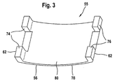
- the friction element 55 is shown in detail in FIG. 3.
- the grater menu 55 is domed and not flat.
- the friction element 55 comprises a front side 78 and a back 80.
- the back 80 is before the assembly of the Friction elements 55 on the second end region 10 of the pedal arm 6
- Adhesive 66 is applied, which is designed as an adhesive film.
- the friction element 55 with Help of the captive 62 designed as webs 74 and 76 in the Recesses 64 of the second end region 10 of the pedal arm 6 are fitted.
- the front side 78 of the friction element 55 then forms in the pedal 2 the friction surface 56.
- the separate version of the Friction elements 56 and the second end region 10 of the pedal arm 6 also enables a lightweight construction of the second end region 10 of the pedal arm 6.
- the wear resistance of the friction surface 56 due to the material of the friction element 55 which is designed as a metal reliably guaranteed.
- one Surface treatment of the front 78 of the friction element 56 die Ensure wear resistance of the friction surface 56. Due to the Space-saving design, such a pedal is particularly suitable for Use in motor vehicles as an accelerator pedal.
Landscapes
- Physics & Mathematics (AREA)
- General Physics & Mathematics (AREA)
- Engineering & Computer Science (AREA)
- Automation & Control Theory (AREA)
- Mechanical Control Devices (AREA)
- Auxiliary Drives, Propulsion Controls, And Safety Devices (AREA)
Abstract
Description
- FIG 1
- schematisch eine Seitenansicht eines Pedals,
- FIG 2
- schematisch einen Schnitt durch die Seitenansicht des Pedals gemäß Figur 1 und
- FIG 3
- schematisch ein Reibelement gemäß den Figuren 1 und 2.
Claims (12)
- Pedal (2), insbesondere für ein Kraftfahrzeug, mit einem Pedalarm (6), welcher an seinem ersten Endbereich (8) von einer Kraft (4), insbesondere einer Fußkraft, auslenkbar und an seinem zweiten Endbereich (10) um eine in einem Gehäuse (16) gelagerte Schwenkachse (18) schwenkbar gelagert und von einem die Schwenkachse (18) umschließenden Rückstellfederelement (20) in eine Grundstellung zurückschwenkbar beaufschlagt ist, wobei das Rückstellfederelement (20) an einem ersten Hebelarm (36) eines schwenkbar gelagerten Hebels (38) abgestützt ist, dessen zweiter Hebelarm (44) über einen Reibkörper (50) an einer um die Schwenkachse (18) des Pedalarms (2) schwenkbaren und an dem zweiten Endbereich (10) des Pedalarms angeordneten Reibfläche (56) in Anlage ist dadurch gekennzeichnet, daß die Reibfläche (56) Bestandteil eines Reibelements (55) ist und der zweite Endbereich (10) des Pedalarms (6) mit dem Reibelement (55) über einen Haftstoff (66) fest verbunden ist.
- Pedal (2) nach Anspruch 1, dadurch gekennzeichnet, daß der Haftstoff (66) als beidseitig klebende Folie ausgebildet ist.
- Pedal (2) nach Anspruch 1 oder 2 dadurch gekennzeichnet, daß das die Reibfläche (56) umfassende Reibelement (55) formschlüssig an dem zweiten Endbereich (10) des Pedalarms (6) angeordnet ist.
- Pedal (2) nach einem der Ansprüche 1 bis 3 dadurch gekennzeichnet, daß die Oberfläche des zweiten Endbereichs (10) des Pedalarms (6) und die Reibfläche (56) verschiedene Materialeigenschaften aufweisen.
- Pedal (2) nach einem der Ansprüche 1 bis 4 dadurch gekennzeichnet, daß der zweite Endbereich (10) des Pedalarms (6) aus einem ersten Material (58) und das die Reibfläche (56) umfassende Reibelement (55) aus einem von dem ersten Material (58) verschiedenen zweiten Material (60) gefertigt ist.
- Pedal (2) nach Anspruch 5 dadurch gekennzeichnet, daß das erste Material (58) Kunststoff und das zweite Material (60) Metall ist.
- Pedal (2) nach einem der Ansprüche 1 bis 6 dadurch gekennzeichnet, daß der erste Hebelarm (36) des Hebels (38) an der dem Pedalarm (6) abgewandten Seite einen den Schwenkbereich des Hebels (38) begrenzenden Verschleißanschlag (52) aufweist, der gegen einen Anschlag (54) beaufschlagbar ist.
- Pedal (2) nach einem der Ansprüche 1 bis 7 dadurch gekennzeichnet, daß der zweite Endbereich (10) des Pedalarms (6) eine Führung (22) aufweist, in der das Rückstellfederelement (20) angeordnet ist.
- Pedal (2) nach einem der Ansprüche 1 bis 8 dadurch gekennzeichnet, daß das Rückstellfederelement (20) an seinem äußeren Ende (32) gegen ein an dem ersten Hebelarm (36) des Hebels (38) ausgebildetes Widerlager (34) beaufschlagbar ist.
- Pedal (2) nach Anspruch 9 dadurch gekennzeichnet, daß das äußere Ende (30) des Rückstellfederelements (20) gegen einen die Richtung der Kraft des Rückstellfederelements (20) bestimmenden Stützkörper (40) in Anlage ist.
- Pedal (2) nach einem der Ansprüche 1 bis 10 dadurch gekennzeichnet, daß das Rückstellfederelement (20) als doppelte Schenkelfeder ausgebildet ist.
- Pedal (2) nach Anspruch 11 dadurch gekennzeichnet, daß das Rückstellfederelement (20) als biferal gewickelte Torsionsfeder ausgebildet ist.
Applications Claiming Priority (2)
| Application Number | Priority Date | Filing Date | Title |
|---|---|---|---|
| DE10007743 | 2000-02-19 | ||
| DE10007743A DE10007743A1 (de) | 2000-02-19 | 2000-02-19 | Pedal |
Publications (3)
| Publication Number | Publication Date |
|---|---|
| EP1126353A2 true EP1126353A2 (de) | 2001-08-22 |
| EP1126353A3 EP1126353A3 (de) | 2002-05-22 |
| EP1126353B1 EP1126353B1 (de) | 2006-08-02 |
Family
ID=7631642
Family Applications (1)
| Application Number | Title | Priority Date | Filing Date |
|---|---|---|---|
| EP01100945A Expired - Lifetime EP1126353B1 (de) | 2000-02-19 | 2001-01-17 | Pedal |
Country Status (5)
| Country | Link |
|---|---|
| US (1) | US6453768B2 (de) |
| EP (1) | EP1126353B1 (de) |
| JP (1) | JP2001260697A (de) |
| KR (1) | KR100780114B1 (de) |
| DE (2) | DE10007743A1 (de) |
Cited By (4)
| Publication number | Priority date | Publication date | Assignee | Title |
|---|---|---|---|---|
| EP1943577A4 (de) * | 2005-10-31 | 2009-11-25 | Grand Haven Stamped Prod | Pedal mit hysteresemechanismus |
| WO2013079249A1 (de) * | 2011-12-01 | 2013-06-06 | Robert Bosch Gmbh | Pedalwertgeberanordnung |
| US10296037B2 (en) | 2015-09-18 | 2019-05-21 | Kongsberg Power Products Systems I, Inc. | Pedal assembly with identical first and second housing components |
| US10551866B2 (en) | 2015-09-18 | 2020-02-04 | Kongsberg Power Products Systems I, Inc. | Pedal assembly with debris filtering mechanism |
Families Citing this family (12)
| Publication number | Priority date | Publication date | Assignee | Title |
|---|---|---|---|---|
| SE518099C2 (sv) | 1997-11-21 | 2002-08-27 | Claes Johansson Automotive Ab | Inställbart pedalställ för ett fordon |
| US6622589B1 (en) * | 1999-11-19 | 2003-09-23 | Aptek Williams, Inc. | Manual control apparatus |
| DE10007743A1 (de) * | 2000-02-19 | 2001-08-23 | Mannesmann Vdo Ag | Pedal |
| WO2004007929A2 (en) * | 2002-07-17 | 2004-01-22 | Ksr International Co. | Electronic throttle control with hysteresis device |
| KR100614524B1 (ko) * | 2005-08-22 | 2006-08-25 | (주) 동희산업 | 가속페달의 반력 조절 장치 |
| JP4831472B2 (ja) * | 2006-02-09 | 2011-12-07 | 株式会社デンソー | ペダルモジュール |
| DE102008003296B4 (de) | 2008-01-05 | 2016-04-28 | Hella Kgaa Hueck & Co. | Fahrpedal |
| DE102008018140B4 (de) | 2008-04-10 | 2021-01-28 | HELLA GmbH & Co. KGaA | Fahrpedal |
| DE102009032664B4 (de) | 2009-07-09 | 2016-05-12 | Hella Kgaa Hueck & Co. | Fahrpedal |
| FI20095868A0 (fi) * | 2009-08-24 | 2009-08-24 | Polar Electro Oy | Poljinmittaus |
| DE102014102758A1 (de) * | 2014-03-03 | 2015-09-03 | Hella Kgaa Hueck & Co. | Fahrpedalgeber |
| DE102014106329B4 (de) | 2014-05-07 | 2025-02-13 | HELLA GmbH & Co. KGaA | Fahrpedal |
Citations (1)
| Publication number | Priority date | Publication date | Assignee | Title |
|---|---|---|---|---|
| DE19811442A1 (de) | 1998-03-17 | 1999-09-23 | Mannesmann Vdo Ag | Pedal |
Family Cites Families (21)
| Publication number | Priority date | Publication date | Assignee | Title |
|---|---|---|---|---|
| DE2327548A1 (de) * | 1973-05-30 | 1974-12-19 | Jurid Werke Gmbh | Reibungs-bremse oder -kupplung |
| JPH0790756B2 (ja) * | 1987-06-08 | 1995-10-04 | 日本発条株式会社 | 足踏み式駐車ブレーキ |
| JPH03284455A (ja) * | 1990-03-31 | 1991-12-16 | Oi Seisakusho Co Ltd | 足踏み式パーキングブレーキ装置 |
| US5233882A (en) * | 1990-07-12 | 1993-08-10 | General Motors Corporation | Remote control lever module |
| KR100251977B1 (ko) * | 1991-10-29 | 2000-04-15 | 구로이시 이쿠오 | 자동차용 발놀림 파킹 브레이크 및 이것에 사용되는 일방향 댐퍼 |
| US5261512A (en) * | 1992-09-08 | 1993-11-16 | Rome Tool & Die Co., Inc. | Brake shoe assembly with sealing liner |
| DE4300096C2 (de) * | 1993-01-05 | 1998-02-05 | Mannesmann Vdo Ag | Fahrpedal mit Drehpotentiometer |
| DE4426549C2 (de) * | 1994-07-27 | 1999-05-20 | Mannesmann Vdo Ag | Fahrpedal mit Sollwertgeber |
| DE19514541C2 (de) * | 1995-04-20 | 1998-01-15 | Daimler Benz Ag | Gaspedal mit Reibkörper |
| DE19517172B4 (de) * | 1995-05-10 | 2009-07-16 | Continental Automotive Gmbh | Fahrpedal für eine Leistungssteuerung einer Brennkraftmaschine |
| US6003404A (en) * | 1995-05-10 | 1999-12-21 | Vdo Adolf Schindling Ag | Accelerator pedal assembly for controlling the power of an internal combustion engine |
| JP3284455B2 (ja) | 1995-06-27 | 2002-05-20 | 日本ビクター株式会社 | ブラシレスモータ |
| US5819593A (en) * | 1995-08-09 | 1998-10-13 | Comcorp Technologies, Inc. | Electronic adjustable pedal assembly |
| DE19536699A1 (de) * | 1995-09-30 | 1997-04-03 | Bosch Gmbh Robert | Fahrpedalmodul |
| DE19536606A1 (de) * | 1995-09-30 | 1997-04-03 | Bosch Gmbh Robert | Fahrpedalmodul |
| GB9604039D0 (en) * | 1996-02-26 | 1996-04-24 | Rearsby Automotive Ltd | Damped pedal mounting |
| DE19720390A1 (de) * | 1997-05-15 | 1998-11-19 | Mannesmann Vdo Ag | Pedal |
| DE19737289A1 (de) * | 1997-08-27 | 1999-03-04 | Mannesmann Vdo Ag | Steuereinrichtung |
| DE19755980A1 (de) * | 1997-12-17 | 1999-06-24 | Mannesmann Vdo Ag | Pedal |
| US6186025B1 (en) * | 1999-03-24 | 2001-02-13 | Teleflex, Inc. | Break away pedal |
| DE10007743A1 (de) * | 2000-02-19 | 2001-08-23 | Mannesmann Vdo Ag | Pedal |
-
2000
- 2000-02-19 DE DE10007743A patent/DE10007743A1/de not_active Ceased
-
2001
- 2001-01-17 DE DE50110575T patent/DE50110575D1/de not_active Expired - Lifetime
- 2001-01-17 EP EP01100945A patent/EP1126353B1/de not_active Expired - Lifetime
- 2001-02-09 US US09/780,562 patent/US6453768B2/en not_active Expired - Fee Related
- 2001-02-19 KR KR1020010008120A patent/KR100780114B1/ko not_active Expired - Fee Related
- 2001-02-19 JP JP2001042483A patent/JP2001260697A/ja not_active Withdrawn
Patent Citations (1)
| Publication number | Priority date | Publication date | Assignee | Title |
|---|---|---|---|---|
| DE19811442A1 (de) | 1998-03-17 | 1999-09-23 | Mannesmann Vdo Ag | Pedal |
Cited By (5)
| Publication number | Priority date | Publication date | Assignee | Title |
|---|---|---|---|---|
| EP1943577A4 (de) * | 2005-10-31 | 2009-11-25 | Grand Haven Stamped Prod | Pedal mit hysteresemechanismus |
| US7793566B2 (en) | 2005-10-31 | 2010-09-14 | Grand Haven Stamped Products Company, Division Of Jsj Corporation | Pedal with hysteresis mechanism |
| WO2013079249A1 (de) * | 2011-12-01 | 2013-06-06 | Robert Bosch Gmbh | Pedalwertgeberanordnung |
| US10296037B2 (en) | 2015-09-18 | 2019-05-21 | Kongsberg Power Products Systems I, Inc. | Pedal assembly with identical first and second housing components |
| US10551866B2 (en) | 2015-09-18 | 2020-02-04 | Kongsberg Power Products Systems I, Inc. | Pedal assembly with debris filtering mechanism |
Also Published As
| Publication number | Publication date |
|---|---|
| KR20010082748A (ko) | 2001-08-30 |
| US6453768B2 (en) | 2002-09-24 |
| EP1126353A3 (de) | 2002-05-22 |
| US20010029805A1 (en) | 2001-10-18 |
| JP2001260697A (ja) | 2001-09-26 |
| EP1126353B1 (de) | 2006-08-02 |
| DE10007743A1 (de) | 2001-08-23 |
| DE50110575D1 (de) | 2006-09-14 |
| KR100780114B1 (ko) | 2007-11-27 |
Similar Documents
| Publication | Publication Date | Title |
|---|---|---|
| EP1126353B1 (de) | Pedal | |
| DE10121317B4 (de) | Pedaleinrichtung | |
| DE102016000023B4 (de) | Kraftfahrzeug-Reduziereinrichtung | |
| DE102017207417B4 (de) | Vorrichtung zur Kraftsimulation an einem Betätigungselement eines Fahrzeugs und elektrisch betätigtes Kupplungssystem | |
| EP0924591A2 (de) | Pedal | |
| EP3477154B1 (de) | Spannvorrichtung | |
| DE69919100T2 (de) | Gaspedal-mechanismus für fahrzeug | |
| EP3338155B1 (de) | Pedalvorrichtung mit dämpfung der betätigung | |
| EP0981786B1 (de) | Pedal | |
| EP0995624B1 (de) | Fahrpedalmodul | |
| WO2008046563A1 (de) | Ventilvorrichtung | |
| DE10297538B4 (de) | Pedal mit unmittelbarer Kraftrückkopplung | |
| DE102008018140B4 (de) | Fahrpedal | |
| DE10065329B4 (de) | Beschleunigungsvorrichtung mit Anbringung an Pedalarm | |
| EP0923015A2 (de) | Pedal | |
| DE19936733C2 (de) | Betätigungseinrichtung für eine Feststellbremse | |
| DE102010056007A1 (de) | Vorspanneinrichtung, Servoeinheit, Lenksystem und Kraftfahrzeug | |
| EP1063403B1 (de) | Lastverstellvorrichtung | |
| DE19517172B4 (de) | Fahrpedal für eine Leistungssteuerung einer Brennkraftmaschine | |
| EP0981459B1 (de) | Pedal | |
| EP3724056B1 (de) | Elektrisch verstellbare lenksäule für ein kraftfahrzeug | |
| EP3943778B1 (de) | Riemenspannvorrichtung und riementrieb mit einer solchen riemenspannvorrichtung | |
| WO1998051529A1 (de) | Beidseitig wirkender antrieb | |
| EP2861478A2 (de) | Arretiervorrichtung zum arretieren einer bewegbaren komponente | |
| DE10328554A1 (de) | Pedal |
Legal Events
| Date | Code | Title | Description |
|---|---|---|---|
| PUAI | Public reference made under article 153(3) epc to a published international application that has entered the european phase |
Free format text: ORIGINAL CODE: 0009012 |
|
| AK | Designated contracting states |
Kind code of ref document: A2 Designated state(s): AT BE CH CY DE DK ES FI FR GB GR IE IT LI LU MC NL PT SE TR |
|
| AX | Request for extension of the european patent |
Free format text: AL;LT;LV;MK;RO;SI |
|
| RAP1 | Party data changed (applicant data changed or rights of an application transferred) |
Owner name: SIEMENS AKTIENGESELLSCHAFT |
|
| PUAL | Search report despatched |
Free format text: ORIGINAL CODE: 0009013 |
|
| AX | Request for extension of the european patent |
Free format text: AL;LT;LV;MK;RO;SI |
|
| 17P | Request for examination filed |
Effective date: 20020618 |
|
| AKX | Designation fees paid |
Designated state(s): DE FR GB |
|
| GRAP | Despatch of communication of intention to grant a patent |
Free format text: ORIGINAL CODE: EPIDOSNIGR1 |
|
| GRAS | Grant fee paid |
Free format text: ORIGINAL CODE: EPIDOSNIGR3 |
|
| GRAA | (expected) grant |
Free format text: ORIGINAL CODE: 0009210 |
|
| AK | Designated contracting states |
Kind code of ref document: B1 Designated state(s): DE FR GB |
|
| REG | Reference to a national code |
Ref country code: GB Ref legal event code: FG4D Free format text: NOT ENGLISH |
|
| REF | Corresponds to: |
Ref document number: 50110575 Country of ref document: DE Date of ref document: 20060914 Kind code of ref document: P |
|
| GBT | Gb: translation of ep patent filed (gb section 77(6)(a)/1977) |
Effective date: 20061018 |
|
| ET | Fr: translation filed | ||
| PLBE | No opposition filed within time limit |
Free format text: ORIGINAL CODE: 0009261 |
|
| STAA | Information on the status of an ep patent application or granted ep patent |
Free format text: STATUS: NO OPPOSITION FILED WITHIN TIME LIMIT |
|
| 26N | No opposition filed |
Effective date: 20070503 |
|
| PGFP | Annual fee paid to national office [announced via postgrant information from national office to epo] |
Ref country code: GB Payment date: 20090122 Year of fee payment: 9 |
|
| GBPC | Gb: european patent ceased through non-payment of renewal fee |
Effective date: 20100117 |
|
| PG25 | Lapsed in a contracting state [announced via postgrant information from national office to epo] |
Ref country code: GB Free format text: LAPSE BECAUSE OF NON-PAYMENT OF DUE FEES Effective date: 20100117 |
|
| REG | Reference to a national code |
Ref country code: FR Ref legal event code: TP |
|
| REG | Reference to a national code |
Ref country code: FR Ref legal event code: PLFP Year of fee payment: 15 |
|
| PGFP | Annual fee paid to national office [announced via postgrant information from national office to epo] |
Ref country code: DE Payment date: 20150131 Year of fee payment: 15 |
|
| PGFP | Annual fee paid to national office [announced via postgrant information from national office to epo] |
Ref country code: FR Payment date: 20150122 Year of fee payment: 15 |
|
| REG | Reference to a national code |
Ref country code: DE Ref legal event code: R119 Ref document number: 50110575 Country of ref document: DE |
|
| REG | Reference to a national code |
Ref country code: FR Ref legal event code: ST Effective date: 20160930 |
|
| PG25 | Lapsed in a contracting state [announced via postgrant information from national office to epo] |
Ref country code: DE Free format text: LAPSE BECAUSE OF NON-PAYMENT OF DUE FEES Effective date: 20160802 |
|
| PG25 | Lapsed in a contracting state [announced via postgrant information from national office to epo] |
Ref country code: FR Free format text: LAPSE BECAUSE OF NON-PAYMENT OF DUE FEES Effective date: 20160201 |