EP1124091A2 - Luminaire - Google Patents
Luminaire Download PDFInfo
- Publication number
- EP1124091A2 EP1124091A2 EP00125160A EP00125160A EP1124091A2 EP 1124091 A2 EP1124091 A2 EP 1124091A2 EP 00125160 A EP00125160 A EP 00125160A EP 00125160 A EP00125160 A EP 00125160A EP 1124091 A2 EP1124091 A2 EP 1124091A2
- Authority
- EP
- European Patent Office
- Prior art keywords
- holding part
- drag chain
- lamp
- hollow profile
- power lines
- Prior art date
- Legal status (The legal status is an assumption and is not a legal conclusion. Google has not performed a legal analysis and makes no representation as to the accuracy of the status listed.)
- Granted
Links
- 230000015572 biosynthetic process Effects 0.000 description 2
- 229920002457 flexible plastic Polymers 0.000 description 2
- WYTGDNHDOZPMIW-RCBQFDQVSA-N alstonine Natural products C1=CC2=C3C=CC=CC3=NC2=C2N1C[C@H]1[C@H](C)OC=C(C(=O)OC)[C@H]1C2 WYTGDNHDOZPMIW-RCBQFDQVSA-N 0.000 description 1
- 238000013459 approach Methods 0.000 description 1
Images


Classifications
-
- F—MECHANICAL ENGINEERING; LIGHTING; HEATING; WEAPONS; BLASTING
- F21—LIGHTING
- F21V—FUNCTIONAL FEATURES OR DETAILS OF LIGHTING DEVICES OR SYSTEMS THEREOF; STRUCTURAL COMBINATIONS OF LIGHTING DEVICES WITH OTHER ARTICLES, NOT OTHERWISE PROVIDED FOR
- F21V21/00—Supporting, suspending, or attaching arrangements for lighting devices; Hand grips
- F21V21/34—Supporting elements displaceable along a guiding element
Definitions
- the invention relates to a lamp with a holding part and a positionable on the holding part in different positions Lighting part.
- Such adjustable lights have, for example, as a holding part a horizontal rail with a slot in which the Luminous part is kept displaceable.
- the lighting part contains the lamp.
- the lamp can thus together with the lighting part can be moved continuously.
- the power lines are at led such lights through the holding part to the lighting part.
- the length of the Power lines the maximum distance between the lighting part and the inlet opening through which the power lines in the rails are guided.
- the Power lines at one end of the substantially cuboid Rail inserted into the rail. If the distance between the lighting part and the entry opening less than is the maximum distance, form the energy lines in the Rail forcibly a loop. It can therefore happen that when moving the luminaire part the power lines to be damaged. Furthermore, the loose in the rail lying power lines cause jamming of the lighting part. In both cases, the lamp must be completely dismantled become.
- the object of the invention is to provide a lamp in which prevents pinching or damage to the power lines is.
- the holding part has a drag chain which the power lines leading through the holding part to the lighting part wearing.
- a drag chain preferably consists of several stiff chain links that are articulated together are.
- the drag chain does not necessarily have to be a link chain.
- a drag chain also a flexible plastic pipe with predetermined kinks or a flexible plastic strip that lines the power lines bears, used.
- the drag chain has a corresponding one Rigidity so that the power lines always be kept at a distance from the lighting part.
- the power lines therefore have an orderly in every position of the light part Course. It is thus ensured that the power lines not damaged when moving the light part become or a jamming of the lighting part by the power lines occurs.
- the drag chain is preferably designed such that the Power lines are arranged within the drag chain. There the energy lines are therefore surrounded by the drag chain or are shielded by the drag chain is damaging the Energy conduction, for example, by friction between the holding part and prevents energy conduction.
- the holding part is a hollow profile
- the drag chain within the hollow profile is arranged.
- the drag chain is therefore not visible.
- the position of the drag chain in the hollow profile defined, for example, by side walls of the hollow profile.
- guides for the drag chain can be in the hollow profile be provided. A deflection of the drag chain in the direction the adjustment of the lighting part does not occur, so that jamming of the lamp part by the power lines or the drag chain is excluded.
- a drag chain consisting of several chain links are the individual links against each other by only one limited swivel angle pivotable, with adjacent chain links have a common pivot axis.
- the drag chain is designed so that all pivot axes essentially are parallel to each other when the drag chain is in the hollow profile is arranged.
- the individual are preferred Chain links designed so that they from a swivel angle can only be pivoted in one direction from 0 °. This means, that such a drag chain from an uncurved position can only be curved in one direction. This is the Risk of loop formation and the possibility of deflection the drag chain in the adjustment path is also reduced. Because such a drag chain can be used without any special Guides when moving the light part only in certain Moving areas is also the possibility of snagging the drag chain, e.g. with others provided in the holding part Components reduced.
- the holding part has a Guided tour in which one connected to the lighting part Carriage is slidably guided. With the leadership it can it is an elongated projection or individual lugs, engage the corresponding recesses on the carriage.
- the guide is preferably one in the Holding part provided slot, the slide inside of the holding part designed as a hollow profile is arranged.
- the Power lines are here through the slot to the lighting part guided.
- the sled can use appropriate approaches for guidance have, which protrude into the slot.
- the Provide power lines in the area of the slot with a sleeve so that they serve as guide pins.
- the structure of the sled is simplified.
- Luminaire part not continuously adjustable but in different Positions can be connected to the holding part.
- the holding part has several individual fastening elements.
- the fasteners are, for example Hook into which a corresponding one connected to the lighting part Counterpart can be hung.
- the drag chain can again within a holding part designed as a hollow profile be arranged, the holding part also having a slot has through which the power lines out of the holding part are led to the lighting part.
- the lamp according to the invention can be designed as a ceiling lamp be, with a rail then preferably as a holding part longitudinal slot is provided.
- the holding part can also be attached vertically or diagonally to a wall become.
- continuously adjustable Luminaire part is a clamping device or the like. intended, to be able to fix the light part in any position.
- the slot along which the light part can be moved can have different courses, e.g. along a circular line or serpentine. In the embodiment with different fasteners this is not necessary.
- the vertical arrangement of the holding part is also possible with a floor lamp.
- the invention Lamp be a table lamp in which the holding part any Assumes position, and if necessary is also pivotable.
- the in Figs. 1 to 3 shown lamp has a holding part 10 and a light part 12 on.
- the light part points a reflector screen 14 and one within the reflector screen 14 arranged lamp 16 on.
- lead from the holding part 10 power lines 18.20 to the lighting part 12.
- Die Power lines 18, 20 are on the left in FIG. 1 of the Holding part 10 out in the holding part and run inside of the holding part 10.
- the lighting part 12 is in the direction of Arrow 22 displaceable with respect to the holding part 10.
- the holding part 10 designed as a cuboid hollow profile has a longitudinal slot 24.
- a carriage 26 is provided with connected to the lighting part via the power lines 18, 20 is.
- the carriage 26 faces the slot 24 Page has a nose-shaped shoulder 28 that fits into the slot 24 protrudes.
- the nose-shaped projection 28 serves to guide the carriage 26. The carriage 26 can thus along the slot 24th can be moved continuously in the direction of arrow 22.
- the drag chain 30 is provided within the hollow profile 10.
- the drag chain 30 extends from an opening 32 of the holding part 10 to the Carriage 26.
- the length of the arranged in the holding part 10 Lines 18, 20 and the drag chain 30 is dimensioned such that the carriage 26 in both extreme positions, i.e. in Fig. 3 of can be moved from the far left to the far right.
- the drag chain 30 consists of several chain links 34 that are vertical to the longitudinal direction of the drag chain 30 arranged pivot axes 36 are pivotally connected to one another. Because the drag chain 30 is relatively stiff, it runs parallel to a side wall 38 of the rectangular holding part 10.
- Drag chain 30 Depending on the position of the The position of an arc region 40 of the carriage 26 changes Drag chain 30. If the carriage 26 is in the position shown in FIG. 3 Right extreme position, the drag chain 30 is on the side wall 38 and on an end face 42 of the holding part 10. It should be noted here that the drag chain 30 is not may be too long, since the arc region 40 of the Drag chain 30 would otherwise touch the end face 42 before the carriage 26 in the extreme right position in FIG. 3 located. The further the carriage 26 in Fig. 3 after is shifted to the left, the further the arc region 40 moves to the left. In the left extreme position of the carriage in FIG. 3 26 is the drag chain 30 on the side wall 38, the Arc region runs further to the left than shown in FIG. 3 and the remaining part of the drag chain 30 lies on one side wall 44 opposite side wall 38.
- the drag chain 30 is connected to the holding part via a pin 46 10 connected.
- the position of the first chain link 34 is thus relative of the holding part 10 fixed.
- the other end of the drag chain 30 is firmly connected to the carriage 26.
- the power lines 18.20 thus run from a power supply source to the opening 32 of the holding part 10 and are then in the hollow drag chain 30 guided and run through the entire drag chain 30 to the carriage 26.
- the lines 18, 20 then run through corresponding holes in the carriage through this through and leave the carriage 26 at its bottom (Fig. 2). From there, the lines 18, 20 lead to the lighting part 12th
- a U-shaped cover 48 is provided on the side walls the drag chain 30 abuts so that the drag chain 30 can't break out.
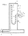
- a holding part 50 of the Floor lamp is also designed as a hollow profile and with a lamp base 52 firmly connected.
- the holding part is for example also cuboid. It can also be about a circular cylinder or around any cylinder act in another form.
- fasteners 54 are provided on a front side 53 of the holding part 50 .
- a light part 56 has a reflector screen 58 and one within the reflector screen 58 arranged lamp 60 on. With the reflector screen 58 a fastening arm 62 is connected.
- the mounting arm 62 has a bore 64. The lighting part 56 can thus in different heights on a corresponding fastener 54 are inserted, then in the bore 64 of the mounting arm 62 protrudes.
- the energy lines 18, 20 are through in this embodiment an opening 66 in the lamp base 52. Run from this them along an inside of the holding member 50 therein upwards, the lines 18, 20 in this area on the Are fixed inside of the holding part 30. In the upper area of the holding part 50, the lines 18, 20 are in the drag chain 30 introduced. The lines 18, 20 run through the drag chain 30, emerge from the end of the drag chain 30 and are provided by a in the front 53 of the holding part 50 Slot led to the light part.
- the beginning of the drag chain 30 is via a bolt 68 with the Holding part 50 firmly connected, so that the first chain link 34 the drag chain 30 is fixed. Otherwise the drag chain hangs 30 free in the holding part 50.
- a clamp connection for strain relief between the lines 18, 20 and the last chain link 34 of the Drag chain can be provided.
Landscapes
- Engineering & Computer Science (AREA)
- General Engineering & Computer Science (AREA)
- Non-Portable Lighting Devices Or Systems Thereof (AREA)
- Vessels And Coating Films For Discharge Lamps (AREA)
- Fastening Of Light Sources Or Lamp Holders (AREA)
- Electric Cable Arrangement Between Relatively Moving Parts (AREA)
Applications Claiming Priority (2)
| Application Number | Priority Date | Filing Date | Title |
|---|---|---|---|
| DE20002141U DE20002141U1 (de) | 2000-02-08 | 2000-02-08 | Leuchte |
| DE20002141U | 2000-02-08 |
Publications (3)
| Publication Number | Publication Date |
|---|---|
| EP1124091A2 true EP1124091A2 (fr) | 2001-08-16 |
| EP1124091A3 EP1124091A3 (fr) | 2003-04-09 |
| EP1124091B1 EP1124091B1 (fr) | 2005-06-01 |
Family
ID=7936957
Family Applications (1)
| Application Number | Title | Priority Date | Filing Date |
|---|---|---|---|
| EP00125160A Expired - Lifetime EP1124091B1 (fr) | 2000-02-08 | 2000-11-18 | Luminaire |
Country Status (3)
| Country | Link |
|---|---|
| EP (1) | EP1124091B1 (fr) |
| AT (1) | ATE296992T1 (fr) |
| DE (2) | DE20002141U1 (fr) |
Cited By (3)
| Publication number | Priority date | Publication date | Assignee | Title |
|---|---|---|---|---|
| DE20205809U1 (de) | 2002-04-12 | 2002-06-27 | Neuhaus Licht GmbH, 59519 Möhnesee | Ausziehbare Pendelleuchte |
| EP1617137A1 (fr) * | 2004-07-15 | 2006-01-18 | Zumtobel Staff GmbH | Dispositif d'éclairage comprenant un boîtier d'alimentation et une armature d'éclairage coulissante |
| CN112490962A (zh) * | 2020-11-09 | 2021-03-12 | 临沂矿业集团有限责任公司 | 一种采煤机电缆保护装置 |
Families Citing this family (3)
| Publication number | Priority date | Publication date | Assignee | Title |
|---|---|---|---|---|
| DE202004013118U1 (de) * | 2004-08-21 | 2006-01-05 | B+M Leuchten Gerd Bonus Gmbh & Co. Kg | Leuchtenhalterung und elektrisches Kontaktelement |
| CN111162498B (zh) * | 2019-12-02 | 2025-02-11 | 赛尔富电子有限公司 | 一种导线可伸缩的防水取电轨道 |
| DE102020116755A1 (de) | 2020-06-25 | 2021-12-30 | Matthias Zundel | Linearantrieb |
Family Cites Families (8)
| Publication number | Priority date | Publication date | Assignee | Title |
|---|---|---|---|---|
| US1606870A (en) * | 1925-03-18 | 1926-11-16 | Harley G Corwin | Adjustable electric fixture with concealed wiring |
| GB942502A (en) * | 1961-07-04 | 1963-11-20 | Rotaflex Ltd | Improvements in electric lighting or like fittings |
| US3284036A (en) * | 1965-05-06 | 1966-11-08 | Nat Crane Corp | Carrier link chain assembly for hoses |
| DE2354544A1 (de) * | 1973-10-31 | 1975-05-15 | Simon & Schelle Lampen Und Met | Leuchte |
| US4118760A (en) * | 1977-01-07 | 1978-10-03 | Cohon Bertram J | Adjustable hanger for electric lights |
| DE3820953A1 (de) | 1988-06-16 | 1989-12-28 | Mannesmann Ag | Einrichtung zum steuern eines krans |
| DE9217204U1 (de) | 1992-12-16 | 1993-04-08 | Kosak, Günter, 8903 Bobingen | Verstellbare Deckenlampenhalterung |
| US5649415A (en) * | 1995-02-02 | 1997-07-22 | Hubbell Incorporated | Power supply chain and chain carriage system |
-
2000
- 2000-02-08 DE DE20002141U patent/DE20002141U1/de not_active Expired - Lifetime
- 2000-11-18 AT AT00125160T patent/ATE296992T1/de not_active IP Right Cessation
- 2000-11-18 DE DE50010451T patent/DE50010451D1/de not_active Expired - Lifetime
- 2000-11-18 EP EP00125160A patent/EP1124091B1/fr not_active Expired - Lifetime
Non-Patent Citations (1)
| Title |
|---|
| None |
Cited By (4)
| Publication number | Priority date | Publication date | Assignee | Title |
|---|---|---|---|---|
| DE20205809U1 (de) | 2002-04-12 | 2002-06-27 | Neuhaus Licht GmbH, 59519 Möhnesee | Ausziehbare Pendelleuchte |
| EP1617137A1 (fr) * | 2004-07-15 | 2006-01-18 | Zumtobel Staff GmbH | Dispositif d'éclairage comprenant un boîtier d'alimentation et une armature d'éclairage coulissante |
| CN112490962A (zh) * | 2020-11-09 | 2021-03-12 | 临沂矿业集团有限责任公司 | 一种采煤机电缆保护装置 |
| CN112490962B (zh) * | 2020-11-09 | 2022-03-11 | 临沂矿业集团有限责任公司 | 一种采煤机电缆保护装置 |
Also Published As
| Publication number | Publication date |
|---|---|
| DE20002141U1 (de) | 2000-03-30 |
| ATE296992T1 (de) | 2005-06-15 |
| DE50010451D1 (de) | 2005-07-07 |
| EP1124091B1 (fr) | 2005-06-01 |
| EP1124091A3 (fr) | 2003-04-09 |
Similar Documents
| Publication | Publication Date | Title |
|---|---|---|
| DE3318365C2 (fr) | ||
| EP2427401B1 (fr) | Elément de suspension d'un dispositif à câble pendant | |
| EP1124091B1 (fr) | Luminaire | |
| DE2736037A1 (de) | Steigschutzvorrichtung zum besteigen einer leiter | |
| DE685079C (de) | Kratzfoerderer | |
| DE2608289B2 (de) | Befestigung von Kratzern an einer als Rundgliederkette ausgebildeten Langstrangkette eines Kettenkratzförderers | |
| DE3319773C2 (de) | Bauteil für Rundgliederketten | |
| EP0885995B1 (fr) | Dispositif pour sécher le linge | |
| DE4300415C2 (de) | Reflektorverbinder für ein Lichtband | |
| DE202010005647U1 (de) | Mehrteilige Kettenfestsetzeinrichtung, Rinnenelement und Teile hierfür | |
| DE2228059C3 (de) | Schienenlager für einen Kettfadenwächter | |
| EP0693638B1 (fr) | Chaine de support d'au moins un conducteur d'énergie et procédé d'introduction du conducteur dans la chaine | |
| DE3816305A1 (de) | Rueckenschutz fuer eine leiter | |
| DE3710609A1 (de) | Aufhaengevorrichtung fuer haengeleuchten | |
| EP0278266B1 (fr) | Raccord à charniére et son application | |
| DE10337126B3 (de) | Kranbahnschiene | |
| DE19740498A1 (de) | Werkzeuggreifer für einen Speicherplatz eines Kettenmagazines an einer Werkzeugmaschine | |
| DE29505055U1 (de) | Haltevorrichtung | |
| DE19547221B4 (de) | Endlasche für Energieführungskette | |
| DE19808914B4 (de) | Hängeleuchte mit einer Seilsicherung und zugehöriger Seilhalter | |
| DE3902261C2 (de) | Fädel- und Halterungsgerät zum Auf- oder Abfädeln von an Gardinen befestigten Gardinenrollen | |
| DE2513118A1 (de) | Leitvorrichtung fuer versorgungsleitungen bei gewinnungsmaschinen im bergbau | |
| DE1073177B (de) | Klemmvorrichtung für die Verbindung des Förderseils mit einer im Schacht angeordneten Tragbühne | |
| DE9206550U1 (de) | Hängefördersystem | |
| DE2944024C2 (de) | Innenbeleuchtetes Verkehrszeichen o.dgl. |
Legal Events
| Date | Code | Title | Description |
|---|---|---|---|
| PUAI | Public reference made under article 153(3) epc to a published international application that has entered the european phase |
Free format text: ORIGINAL CODE: 0009012 |
|
| AK | Designated contracting states |
Kind code of ref document: A2 Designated state(s): AT BE CH CY DE DK ES FI FR GB GR IE IT LI LU MC NL PT SE TR |
|
| AX | Request for extension of the european patent |
Free format text: AL;LT;LV;MK;RO;SI |
|
| PUAL | Search report despatched |
Free format text: ORIGINAL CODE: 0009013 |
|
| AK | Designated contracting states |
Kind code of ref document: A3 Designated state(s): AT BE CH CY DE DK ES FI FR GB GR IE IT LI LU MC NL PT SE TR |
|
| AX | Request for extension of the european patent |
Extension state: AL LT LV MK RO SI |
|
| RIC1 | Information provided on ipc code assigned before grant |
Ipc: 7F 21V 27/00 B Ipc: 7F 21V 21/34 A Ipc: 7H 02G 11/00 B Ipc: 7F 16G 13/16 B |
|
| 17P | Request for examination filed |
Effective date: 20030523 |
|
| 17Q | First examination report despatched |
Effective date: 20030812 |
|
| AKX | Designation fees paid |
Designated state(s): AT CH DE IT LI NL |
|
| GRAP | Despatch of communication of intention to grant a patent |
Free format text: ORIGINAL CODE: EPIDOSNIGR1 |
|
| GRAS | Grant fee paid |
Free format text: ORIGINAL CODE: EPIDOSNIGR3 |
|
| GRAA | (expected) grant |
Free format text: ORIGINAL CODE: 0009210 |
|
| AK | Designated contracting states |
Kind code of ref document: B1 Designated state(s): AT CH DE IT LI NL |
|
| PG25 | Lapsed in a contracting state [announced via postgrant information from national office to epo] |
Ref country code: IT Free format text: LAPSE BECAUSE OF FAILURE TO SUBMIT A TRANSLATION OF THE DESCRIPTION OR TO PAY THE FEE WITHIN THE PRESCRIBED TIME-LIMIT;WARNING: LAPSES OF ITALIAN PATENTS WITH EFFECTIVE DATE BEFORE 2007 MAY HAVE OCCURRED AT ANY TIME BEFORE 2007. THE CORRECT EFFECTIVE DATE MAY BE DIFFERENT FROM THE ONE RECORDED. Effective date: 20050601 |
|
| REG | Reference to a national code |
Ref country code: CH Ref legal event code: EP Ref country code: CH Ref legal event code: NV Representative=s name: ISLER & PEDRAZZINI AG |
|
| REG | Reference to a national code |
Ref country code: IE Ref legal event code: FG4D Free format text: LANGUAGE OF EP DOCUMENT: GERMAN |
|
| REF | Corresponds to: |
Ref document number: 50010451 Country of ref document: DE Date of ref document: 20050707 Kind code of ref document: P |
|
| PGFP | Annual fee paid to national office [announced via postgrant information from national office to epo] |
Ref country code: NL Payment date: 20051117 Year of fee payment: 6 |
|
| PGFP | Annual fee paid to national office [announced via postgrant information from national office to epo] |
Ref country code: AT Payment date: 20051122 Year of fee payment: 6 |
|
| PGFP | Annual fee paid to national office [announced via postgrant information from national office to epo] |
Ref country code: CH Payment date: 20051123 Year of fee payment: 6 |
|
| PLBE | No opposition filed within time limit |
Free format text: ORIGINAL CODE: 0009261 |
|
| STAA | Information on the status of an ep patent application or granted ep patent |
Free format text: STATUS: NO OPPOSITION FILED WITHIN TIME LIMIT |
|
| 26N | No opposition filed |
Effective date: 20060302 |
|
| PG25 | Lapsed in a contracting state [announced via postgrant information from national office to epo] |
Ref country code: AT Free format text: LAPSE BECAUSE OF NON-PAYMENT OF DUE FEES Effective date: 20061118 |
|
| PG25 | Lapsed in a contracting state [announced via postgrant information from national office to epo] |
Ref country code: CH Free format text: LAPSE BECAUSE OF NON-PAYMENT OF DUE FEES Effective date: 20061130 Ref country code: LI Free format text: LAPSE BECAUSE OF NON-PAYMENT OF DUE FEES Effective date: 20061130 |
|
| PG25 | Lapsed in a contracting state [announced via postgrant information from national office to epo] |
Ref country code: NL Free format text: LAPSE BECAUSE OF NON-PAYMENT OF DUE FEES Effective date: 20070601 |
|
| REG | Reference to a national code |
Ref country code: CH Ref legal event code: PL |
|
| NLV4 | Nl: lapsed or anulled due to non-payment of the annual fee |
Effective date: 20070601 |
|
| PGFP | Annual fee paid to national office [announced via postgrant information from national office to epo] |
Ref country code: DE Payment date: 20121207 Year of fee payment: 13 |
|
| REG | Reference to a national code |
Ref country code: DE Ref legal event code: R119 Ref document number: 50010451 Country of ref document: DE Effective date: 20140603 |
|
| PG25 | Lapsed in a contracting state [announced via postgrant information from national office to epo] |
Ref country code: DE Free format text: LAPSE BECAUSE OF NON-PAYMENT OF DUE FEES Effective date: 20140603 |