EP1123515B1 - Bloc-batterie dote d'un indicateur d'etat de charge - Google Patents
Bloc-batterie dote d'un indicateur d'etat de charge Download PDFInfo
- Publication number
- EP1123515B1 EP1123515B1 EP99955060A EP99955060A EP1123515B1 EP 1123515 B1 EP1123515 B1 EP 1123515B1 EP 99955060 A EP99955060 A EP 99955060A EP 99955060 A EP99955060 A EP 99955060A EP 1123515 B1 EP1123515 B1 EP 1123515B1
- Authority
- EP
- European Patent Office
- Prior art keywords
- battery
- charge
- discharge
- battery pack
- display
- Prior art date
- Legal status (The legal status is an assumption and is not a legal conclusion. Google has not performed a legal analysis and makes no representation as to the accuracy of the status listed.)
- Expired - Lifetime
Links
Images


Classifications
-
- H—ELECTRICITY
- H01—ELECTRIC ELEMENTS
- H01M—PROCESSES OR MEANS, e.g. BATTERIES, FOR THE DIRECT CONVERSION OF CHEMICAL ENERGY INTO ELECTRICAL ENERGY
- H01M10/00—Secondary cells; Manufacture thereof
- H01M10/42—Methods or arrangements for servicing or maintenance of secondary cells or secondary half-cells
- H01M10/48—Accumulators combined with arrangements for measuring, testing or indicating the condition of cells, e.g. the level or density of the electrolyte
-
- H—ELECTRICITY
- H02—GENERATION; CONVERSION OR DISTRIBUTION OF ELECTRIC POWER
- H02J—CIRCUIT ARRANGEMENTS OR SYSTEMS FOR SUPPLYING OR DISTRIBUTING ELECTRIC POWER; SYSTEMS FOR STORING ELECTRIC ENERGY
- H02J7/00—Circuit arrangements for charging or depolarising batteries or for supplying loads from batteries
- H02J7/0047—Circuit arrangements for charging or depolarising batteries or for supplying loads from batteries with monitoring or indicating devices or circuits
- H02J7/0048—Detection of remaining charge capacity or state of charge [SOC]
-
- H—ELECTRICITY
- H01—ELECTRIC ELEMENTS
- H01M—PROCESSES OR MEANS, e.g. BATTERIES, FOR THE DIRECT CONVERSION OF CHEMICAL ENERGY INTO ELECTRICAL ENERGY
- H01M6/00—Primary cells; Manufacture thereof
- H01M6/50—Methods or arrangements for servicing or maintenance, e.g. for maintaining operating temperature
- H01M6/5044—Cells or batteries structurally combined with cell condition indicating means
-
- Y—GENERAL TAGGING OF NEW TECHNOLOGICAL DEVELOPMENTS; GENERAL TAGGING OF CROSS-SECTIONAL TECHNOLOGIES SPANNING OVER SEVERAL SECTIONS OF THE IPC; TECHNICAL SUBJECTS COVERED BY FORMER USPC CROSS-REFERENCE ART COLLECTIONS [XRACs] AND DIGESTS
- Y02—TECHNOLOGIES OR APPLICATIONS FOR MITIGATION OR ADAPTATION AGAINST CLIMATE CHANGE
- Y02E—REDUCTION OF GREENHOUSE GAS [GHG] EMISSIONS, RELATED TO ENERGY GENERATION, TRANSMISSION OR DISTRIBUTION
- Y02E60/00—Enabling technologies; Technologies with a potential or indirect contribution to GHG emissions mitigation
- Y02E60/10—Energy storage using batteries
Definitions
- This invention relates to batteries for portable devices such as computers, camcorders and cellular phones.
- Batteries are used to power portable electronic equipment. Often batteries are used with equipment that give an indication of an amount of charge left in the battery.
- the charge indicator displays an indication of a percentage of useful power remaining compared to that the full charged battery.
- these indicators are carried by the battery cell and are often of the chemical type.
- the indicators are produced by circuits contained in the electronic device such as the cell phone or the like. When the indicator is produced by the device, the indicator is often a display such as an LCD display of a battery divided into segments. Each segment is lit or enabled to represent a percentage of power left in the battery. As power is drained from the battery segments are turned off with remaining lit ones indicating the remaining power in the battery.
- FR-A-2-615 627 describes a battery monitor that is capable of indicating the remaining discharge time on a display.
- EP 0731 546 describes a battery charger capable of displaying the necessary charging time.
- a battery pack for a portable electronic device includes a case for carrying a battery.
- the case supports a charge sensing circuit carried by the case, the charge sensing circuit producing a discharge signal corresponding to a measurement of an amount of charge removed from a battery.
- the case also supports a processor responsive to the discharge signal from the charge sensor circuit to produce a signal corresponding to an amount of time prior to discharge of the battery based on a current rate of discharge and a display responsive to the signal to display a time period corresponding to the amount of time to discharge the battery based upon the current rate of discharge of the battery.
- the battery pack can include a charge sensor circuit that measures the amount of charge removed from the battery.
- the sensor circuit can be a Coulomb counting circuit that counts an amount of charge units removed from the battery.
- the display can be a liquid crystal display, electrophoretic, or electronic ink display.
- the battery pack can carry at least one battery cell within the case.
- the processor is responsive to a charge signal and produces the signal corresponding to an amount of time prior to discharge based on the charge signal and a discharge signal from the charge sensor circuit.
- the processor produces a signal corresponding to a message that indicates a mode of operation of the battery and the message is displayed by the display.
- the message can correspond to an operation mode or a diagnostic mode.
- a battery pack for a portable electronic device includes a case carrying a battery, the case supporting a charge sensing circuit to produce an electrical signal corresponding to a measurement of an amount of charge removed from the battery and a processor responsive to the electrical signal from the charge sensor circuit to produce a signal corresponding to an amount of time prior to discharge of the battery in accordance with a history of operation of the battery.
- the battery pack also includes a display responsive to the signal indicating the amount of time prior to discharge, to display a time period corresponding to the amount of time to discharge the battery based upon a current mode of operation of the battery.
- a method of indicating time remaining to discharge a battery includes measuring and accumulating an amount of charge removed from the battery, determining the time remaining to discharge the battery from the amount of accumulated charge removed from the battery and from a current mode of operation of the battery and displaying a time period corresponding to the amount of time to discharge the battery.
- a method of indicating time remaining to charge a battery contained in a battery case includes measuring and accumulating an amount of charge inserted into the battery during charging of the battery and determining the time remaining to charge the battery from the amount of accumulated charge inserted into the battery. The method also includes displaying, on a display carried by the battery case, a time period corresponding to the amount of time to charge the battery.
- the display can have fields for displaying several status type messages.
- the processor can cause measurements of charge being removed from a rechargeable battery cell or being added to a rechargeable battery cell. These measurements are used to determine the amount of time that the battery cells have for discharging and charging. The time is calculated in accordance with the maximum capacity of the battery cells, and either the rate of charge or the rate of discharge of the battery cells in accordance with the mode of use, i.e., talk or a standby mode. This simplifies a user's estimate of the ability of the battery to last for a particular use before reaching discharge. Further, because the display is on the battery, its time to discharge can be ascertained by a user without having to attach the battery to a device such as a camcorder or cell phone.
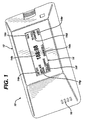
- a battery pack 10 includes a case 12 carrying a display 14.
- the case 12 houses rechargeable battery cells, a controller (as will be described in conjunction with FIG. 2) and an electrical terminal 16 for connection to a user appliance such as a cellular telephone, video camcorder, etc.
- the case 12 can be configured to fit the user appliance.
- the case 12 carries the display 14.
- the display 14 includes a numeric message field which indicates, generally, in hours and minutes, the amount of time left to charge the battery, or to discharge the battery in accordance with the mode of operation of the battery. That is, the display will display a first time to discharge when the battery is in a use mode and a second time remaining to discharge when in a standby mode. These first and second times are determined in accordance with the capacity of the battery and the drain of charge from the battery depending on the mode. Alternatively, the display can display the time to charge the battery during charging operations.
- the display 14 can have fields for displaying several status type messages.
- the display 14 can have a field that indicates the current mode of operation of the battery.
- the "TALK" message 14c can be displayed on a battery used in cellular telephones and indicates that the battery is connected to a phone currently in use, whereas, the "STDY,” message i.e., standby 14e, can be displayed when the battery is in a standby mode of operation.
- the battery can display messages such as "FULL CHARGE NEEDED" 14f, "REPLACE SOON” 14g and "INT EXT” 14a that can be used to indicate whether an internal or external charger in being used.
- the display 14 can display the time "TO FULL CHARGE", and so forth.
- the microprocessor based controller 20 for generating signals to cause appropriate messages to be displayed on display 14 is shown.
- the microprocessor based controller 20 includes a processor 22 fed via a memory 24 having a computer program 40 in the form of software or firmware stored therein which controls operation of the processor 22 and permits the processor 22 to cause measurements of energy being removed from a rechargeable battery cell or being added to a rechargeable battery cell 36. These measurements are used to ascertain the amount of time that the battery cells have for discharging and charging in accordance with the maximum capacity of the battery cells, and either the rate of charge, or the rate of discharge of the battery cells in accordance with the mode or use, i.e., talk or a standby mode.
- leakage of charge from the battery can also calculated. Charge leakage can be based on known or estimated leakage rates.
- the processor controls an A/D converter 26 that provides data corresponding to measurements made of the state of the battery cells 36.
- the A/D converter 26 senses current fed to the battery cells via a charger 30 and also senses current drawn from the rechargeable battery cell via an energy monitor circuit 28.
- the energy monitoring circuit can operate using various known modes. A preferred mode is the so-called "Coulomb counting mode" in which charge that is removed from the battery is determined. Under control of the program 40, the A/D converter will sample these signals and feed these signals to the processor 22 to permit the processor to make the necessary measurements of these parameters.
- the controller 20 as well as charging can be performed via a solar panel 32.
- the rechargeable battery cells 36 can supply current to the controller electronics 20.
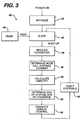
- the program 40 includes an initialization routine 42 which initializes various components in the controller 20, as needed.
- the controller 20 will enter a sleep mode 24 and will remain in that mode unless awakened by a timer signal 43 or some other event.
- the program 40 can exit the sleep mode via an interrupt from the energy monitoring circuit or from software or hardware timers.
- the program causes the processor to read 46 outputs from the analog-to-digital converter (26, FIG. 2).
- the A/D converter (26, FIG. 2) will be fed via the discharge current from the rechargeable battery cells 36 via the energy monitoring circuit 28, as well as, a charging current from the charger 30 depending upon the use of the battery.
- the processor will determine the mode of operation 48 of the battery and call an average current routine that will calculate the average current being drawn from the battery over a period of time. Details on one approach for determining mode of operation are set out in FIG. 4.
- the processor will calculate 50 the remaining capacity of the battery (using a routine 80 FIG. 5, or equivalent) and will determine the end of charge and end of discharge states of the battery 36.
- the processor will calculate the time remaining to discharge or charge the battery in accordance with the mode of operation of the battery and produce signals that are used by a display control routine to enable the various messages 14a-14g on the display 14. Thereafter, the processor resets the operation and returns to a sleep mode 34 awaiting the next event.
- the process 48 for determining the mode of operation of the battery 10 includes determining 60 a direction of current flow from the battery.
- the direction of current flow determines whether the battery is in a use or standby state, or in a charging state. If the direction of current flow is negative, i.e., the battery is being discharged, the process will determine 62 if the current being drawn from the battery exceeds some predetermined threshold for a specified period of time.
- batteries used in cellular telephones or video camcorders have maximum standby currents that can exceed the minimum use currents. Therefore, in order to provide accurate representations of the amount of time available in each mode, it is necessary to filter the current consumption and add current consumption to the proper mode.
- the process 48 determines 62 the amount of current drawn from the battery over a specified period of time. This assumes that the peak currents are exceeded for a specified period of time in a "use" mode; whereas those peak currents are not exceeded over a long period of time during standby mode.
- the process determines 62 that the currents do exceed some threshold for a specified period of time, that indicates that the battery is in a "use” mode such as a "talk" mode for a cellular telephone. Therefore, the current consumed in the "use" mode, i.e., talk, is summed 66 with previous use currents and the time spent in that mode is also incremented. If the threshold was not exceeded for the specified period of time, the battery is in a standby mode and standby currents are added 68 and time in that mode is incremented.
- the mode detection process 48 calculates 72 an average current by dividing total current by the total time in which the battery has been operated.
- the mode detection process 48 then calls a time remaining calculation process 80.
- the time remaining process 80 determines the amount of time remaining to fully discharge the battery or charge the battery depending upon the mode of operation, as determined in FIG. 4.
- One model is a floating average technique in which a moving average of current consumption is calculated separately for the current when the battery is in a "use" mode or a "standby" mode.
- One disadvantage with this approach is that since the process is a moving average, the amount of time to discharge may in fact go up when an average current value goes down relatively quickly. To dampen this effect, a non-floating average can be used in which the average current is updated over very large time intervals with actually learned values. This model provides a smoother output because the amount of current used in the calculations is constant during a calculation cycle.
- An alternative model is a time count model.
- a time count register is decremented to count down the amount of time remaining in the time count register. This technique provides a precise count of time that the battery spends in the various modes.
- the time count model embodiment of the remaining time calculation 80 calculates 82 the remaining time to discharge the battery once per charging cycle and initializes 84 a pair "time remaining to discharge registers" (not shown) with the time value corresponding to the amount of time needed to discharge the battery in accordance with each mode such as "USE” e.g., talk and "STB” e.g., standby, as in Equations 1 and 2.
- REMT,USE CAP/Iavg
- USE REMT,STB CAP/Iavg,STB
- the remaining time is calculated 86 by dividing the capacity of the battery by the average current consumed per time period.
- the use and standby mode time registers contain the remaining time to discharge the battery in accordance with the mode. As a mode is determined 86, each mode register is decremented. Thus for the standby mode, the mode standby register is decremented as in Equation 3, and the use mode register is decremented as in Equation 4.
- RemT,STB RemT,USE - l/min
- RemT,TLK RemT,TLK-Iavg,STB/Iave,USE/min
- the process decrements the standby register, as given in Equation 5 and decrements the use register by an amount of time, as given by Equation 6.
Claims (11)
- Module d'accumulateur (10) pour un dispositif électronique portable, comprenant :caractérisé en ce que le carter supporte :un carter (12) pour contenir un accumulateur,un circuit de détection de charge qui est contenu dans le carter (12), le circuit de détection de charge produisant un signal de décharge correspondant à une charge mesurée qui est enlevée depuis un accumulateur ;un processeur (20) qui est sensible au signal de décharge en provenance du circuit de détection de charge pour produire un signal qui correspond à une quantité de temps restant avant la décharge de l'accumulateur sur la base du niveau de courant de décharge ; etun affichage (14) qui est sensible au signal qui indique la quantité de temps restant avant la décharge de l'accumulateur sur la base du niveau de courant de décharge de l'accumulateur.
- Module d'accumulateur (10) selon la revendication 1, dans lequel le circuit de détection de charge est un circuit de comptage de Coulomb qui compte la quantité d'unités de charge qui sont enlevées depuis l'accumulateur.
- Module d'accumulateur (10) selon la revendication 1, dans lequel l'affichage (14) est un affichage faible puissance.
- Module d'accumulateur (10) selon l'une quelconque des revendications précédentes, dans lequel l'affichage (14) est un affichage à cristaux liquides, un affichage électrophorétique ou un affichage à encre électronique.
- Module d'accumulateur (10) selon l'une quelconque des revendications précédentes, comprenant en outre au moins une cellule d'accumulateur qui est contenue à l'intérieur du carter (12)
- Module d'accumulateur (10) selon l'une quelconque des revendications précédentes, dans lequel le circuit de détection de charge produit un signal de charge qui correspond à la quantité de charges qui sont alimentées sur un accumulateur pendant un mode de fonctionnement de charge.
- Module d'accumulateur (10) selon la revendication 6, dans lequel le processeur (20) est sensible au signal de charge et il produit ledit signal qui correspond à une quantité de temps restant avant la décharge sur la base du signal de charge et du niveau de courant de décharge en provenance du circuit de détecteur de charge.
- Module d'accumulateur (10) selon l'une quelconque des revendications précédentes, dans lequel :le processeur (20) produit un signal qui correspond à un message qui indique un mode de fonctionnement de l'accumulateur ;et dans lequelledit message est affiché par le dispositif d'affichage (14).
- Module d'accumulateur (10) selon la revendication 8, dans lequel le message correspond à un mode de fonctionnement et à un mode par schémas.
- Module d'accumulateur (10) selon l'une quelconque des revendications précédentes, dans lequel le module d'accumulateur comprend en outre un module d'accumulateur et le circuit de détection de charge et le processeur (20) dérivent un courant d'alimentation à partir d'une cellule dans le module d'accumulateur.
- Module d'accumulateur (10) selon l'une quelconque des revendications précédentes, dans lequel :le circuit de détection produit un signal électrique qui correspond à une charge mesurée qui est enlevée depuis l'accumulateur ;le processeur (20) est sensible au signal électrique en provenance du circuit de détection de charge et il produit un signal qui correspond à la quantité de temps restant avant la décharge de l'accumulateur conformément à un historique de fonctionnement de l'accumulateur ; etl'affichage (14) est sensible au signal qui indique la quantité de temps restant avant la décharge, afin d'afficher la période temporelle qui correspond à la quantité de temps restant avant la décharge de l'accumulateur sur la base d'un mode de fonctionnement courant de l'accumulateur.
Applications Claiming Priority (3)
| Application Number | Priority Date | Filing Date | Title |
|---|---|---|---|
| US176574 | 1998-10-21 | ||
| US09/176,574 US6051957A (en) | 1998-10-21 | 1998-10-21 | Battery pack having a state of charge indicator |
| PCT/US1999/024470 WO2000023810A1 (fr) | 1998-10-21 | 1999-10-20 | Bloc-batterie dote d'un indicateur d'etat de charge |
Publications (2)
| Publication Number | Publication Date |
|---|---|
| EP1123515A1 EP1123515A1 (fr) | 2001-08-16 |
| EP1123515B1 true EP1123515B1 (fr) | 2005-04-20 |
Family
ID=22644912
Family Applications (1)
| Application Number | Title | Priority Date | Filing Date |
|---|---|---|---|
| EP99955060A Expired - Lifetime EP1123515B1 (fr) | 1998-10-21 | 1999-10-20 | Bloc-batterie dote d'un indicateur d'etat de charge |
Country Status (10)
| Country | Link |
|---|---|
| US (1) | US6051957A (fr) |
| EP (1) | EP1123515B1 (fr) |
| JP (1) | JP2002528850A (fr) |
| CN (1) | CN1201162C (fr) |
| AR (1) | AR025810A1 (fr) |
| AT (1) | ATE293798T1 (fr) |
| AU (1) | AU1125100A (fr) |
| CA (1) | CA2349570A1 (fr) |
| DE (1) | DE69924860T2 (fr) |
| WO (1) | WO2000023810A1 (fr) |
Families Citing this family (52)
| Publication number | Priority date | Publication date | Assignee | Title |
|---|---|---|---|---|
| JPH10304578A (ja) * | 1997-04-21 | 1998-11-13 | Canon Inc | 電気機器及び電気機器の運用制御方法 |
| US6704133B2 (en) | 1998-03-18 | 2004-03-09 | E-Ink Corporation | Electro-optic display overlays and systems for addressing such displays |
| US7075502B1 (en) | 1998-04-10 | 2006-07-11 | E Ink Corporation | Full color reflective display with multichromatic sub-pixels |
| DE69904185T2 (de) * | 1998-07-08 | 2003-03-27 | E Ink Corp | Verfahren und vorrichtung zum messen des zustandes einer elektrophoretischen anzeigevorrichtung |
| US20030102858A1 (en) * | 1998-07-08 | 2003-06-05 | E Ink Corporation | Method and apparatus for determining properties of an electrophoretic display |
| WO2000013066A1 (fr) * | 1998-08-31 | 2000-03-09 | Citizen Watch Co., Ltd. | Montre electronique ayant une fonction de generation d'electricite |
| US6411911B1 (en) * | 1999-06-30 | 2002-06-25 | Tyco Electronics Logistics Ag | Battery diagnostic method utilizing a universal normalized discharge curve for predicting battery reserve time |
| JP4423764B2 (ja) * | 2000-07-25 | 2010-03-03 | 株式会社ニコン | 電子カメラ |
| US6658270B1 (en) * | 2000-08-18 | 2003-12-02 | Chang-Jung Lee | Displayer-embedded cellular phone battery |
| FR2826125B1 (fr) * | 2001-06-19 | 2003-09-19 | St Microelectronics Sa | Procede et dispositif de controle de l'etat de charge d'un batterie, en particulier une batterie rechargeable pour un telephone mobile cellulaire |
| JP4157317B2 (ja) * | 2002-04-10 | 2008-10-01 | 株式会社日立製作所 | 状態検知装置及びこれを用いた各種装置 |
| KR100532273B1 (ko) * | 2002-10-11 | 2005-11-29 | 삼성전자주식회사 | 복합 단말기에서 동작 모드에 따른 배터리 가용 시간 알림방법 |
| US7140546B1 (en) * | 2002-12-12 | 2006-11-28 | Symbol Technologies, Inc. | Battery pack with integrated human interface devices |
| US6859012B2 (en) * | 2003-02-21 | 2005-02-22 | Thomson Licensing, S.A. | Battery charging apparatus |
| JP3980509B2 (ja) * | 2003-04-01 | 2007-09-26 | 株式会社マキタ | 二次電池装置 |
| WO2005124497A2 (fr) * | 2004-06-14 | 2005-12-29 | Powerprecise Solutions, Inc. | Procede et dispositif servant a controler l'intensite de feux de signalisation |
| US7321521B2 (en) * | 2004-07-02 | 2008-01-22 | Seagate Technology Llc | Assessing energy requirements for a refreshed device |
| DE102004033836B3 (de) * | 2004-07-13 | 2005-09-29 | Siemens Ag | Vorrichtung und Verfahren zur Ermittlung von Betriebsparametern einer Batterie |
| CN100426907C (zh) * | 2004-07-23 | 2008-10-15 | 中兴通讯股份有限公司 | 一种cdma移动终端耗电时长的有线连接测量方法 |
| US7176806B2 (en) * | 2005-02-23 | 2007-02-13 | Eaglepicher Energy Products Corporation | Physical key to facilitate an inactive mode for a state-of-charge indicator within a battery |
| JP4827457B2 (ja) * | 2005-08-11 | 2011-11-30 | 富士通株式会社 | 電子機器およびバッテリ装置 |
| US20080042861A1 (en) * | 2006-08-16 | 2008-02-21 | Bruno Dacquay | Safety battery meter system for surgical hand piece |
| US20080136654A1 (en) * | 2006-12-12 | 2008-06-12 | Motorola, Inc. | Methods and devices for power source life value calculation and representation |
| US7622689B2 (en) * | 2006-12-21 | 2009-11-24 | Integrated Device Technology Inc. | Switch actuator |
| TW200845461A (en) * | 2007-05-04 | 2008-11-16 | Iwei Technology Co Ltd | Recharging apparatus with battery capacity analyzing function |
| FR2916049B1 (fr) * | 2007-05-11 | 2009-07-03 | Commissariat Energie Atomique | Procede de diagnostic d'elements defectueux dans un systeme autonome, alimente par une source d'alimentation intermittente |
| US8358108B2 (en) * | 2007-09-05 | 2013-01-22 | Black & Decker Inc. | System and method for re-initiating charge cycle for battery pack left in a charger |
| US8367235B2 (en) | 2008-01-18 | 2013-02-05 | Mophie, Inc. | Battery pack, holster, and extendible processing and interface platform for mobile devices |
| US20090249095A1 (en) * | 2008-03-26 | 2009-10-01 | Rajesh Poornachandran | User driven power conservation in processor-based systems |
| US7888908B2 (en) * | 2008-04-30 | 2011-02-15 | Visteon Global Technologies, Inc. | Photovoltaic charging system |
| US20100198537A1 (en) * | 2008-12-26 | 2010-08-05 | Panasonic Corporation | Electronic device and method for calculating remaining usable time of battery |
| JP2010246225A (ja) * | 2009-04-03 | 2010-10-28 | Sony Corp | 電池パックおよび充電方法 |
| AT508692B1 (de) | 2009-09-10 | 2015-05-15 | Fronius Int Gmbh | Verfahren und vorrichtung zur energieumwandlung sowie schweissgerät |
| ES2361548B1 (es) * | 2009-10-06 | 2012-04-23 | Viva Developments, S.L | Dispositivo para la presentacion digital de la carga electrica almacenada en dispositivos de almacenamiento de energia electrica |
| WO2011061682A2 (fr) * | 2009-11-17 | 2011-05-26 | Steve Carkner | Indicateur automatique pour la sécurité au cours d'un vol et procédé d'utilisation destiné aux batteries |
| DE102010010443A1 (de) * | 2010-02-25 | 2011-08-25 | Dr. Ing. h.c. F. Porsche Aktiengesellschaft, 70435 | Anzeigevorrichtung eines Kraftfahrzeugs |
| JP5108964B2 (ja) * | 2011-01-14 | 2012-12-26 | 株式会社エヌ・ティ・ティ・ドコモ | 移動機の電池持ち時間を算出する装置及び方法 |
| FR2975543B1 (fr) * | 2011-05-19 | 2015-01-02 | Renault Sa | Systeme et procede d'estimation de l'instant de fin de charge d'une batterie |
| US9190862B2 (en) * | 2012-08-23 | 2015-11-17 | Qualcomm Incorporated | Charging current calibration |
| JP6040743B2 (ja) * | 2012-12-07 | 2016-12-07 | 日立工機株式会社 | 充電装置 |
| WO2014150555A1 (fr) | 2013-03-15 | 2014-09-25 | Mophie, Inc. | Boîtier protecteur pour un dispositif mobile |
| US9889066B2 (en) | 2013-07-01 | 2018-02-13 | Good Fortune 5, Llc | Massaging device having a heat sink |
| BR112016002911A2 (pt) * | 2013-08-13 | 2017-08-01 | Koninklijke Philips Nv | bateria, sistema, e, método |
| US9369656B2 (en) * | 2014-03-31 | 2016-06-14 | Echostar Technologies L.L.C. | Predicting end of battery life for a remote controller device |
| US10079496B2 (en) | 2014-09-03 | 2018-09-18 | Mophie Inc. | Systems for managing charging devices based on battery health information |
| USD861653S1 (en) | 2015-05-27 | 2019-10-01 | Mophie Inc. | Protective battery case for mobile communications device |
| US10416753B1 (en) * | 2015-12-10 | 2019-09-17 | Amazon Technologies, Inc. | Date-based computing device charge management |
| US10429917B2 (en) * | 2017-04-21 | 2019-10-01 | Dell Products L.P. | Calculating a throttle rate for battery current limiting |
| US10516431B2 (en) | 2017-11-21 | 2019-12-24 | Mophie Inc. | Mobile device case for receiving wireless signals |
| USD940647S1 (en) | 2019-01-07 | 2022-01-11 | Mophie Inc. | Battery pack |
| CN111257781A (zh) * | 2020-03-17 | 2020-06-09 | 上海度普新能源科技有限公司 | 下电休眠搁置时间确定方法、健康状态值确定方法及装置 |
| KR102554673B1 (ko) * | 2020-10-13 | 2023-07-13 | 삼성에스디아이 주식회사 | 배터리 팩 |
Citations (1)
| Publication number | Priority date | Publication date | Assignee | Title |
|---|---|---|---|---|
| EP0731546A1 (fr) * | 1995-02-28 | 1996-09-11 | Nec Corporation | Chargeur de batterie capable d'afficher le temps de charge nécessaire |
Family Cites Families (47)
| Publication number | Priority date | Publication date | Assignee | Title |
|---|---|---|---|---|
| US1497388A (en) * | 1922-11-03 | 1924-06-10 | Edward M Sterling | Method of and apparatus for indicating the electrical condition of a cell |
| US2980754A (en) * | 1959-03-23 | 1961-04-18 | Union Carbide Corp | Cell exhaustion indicator |
| US3563806A (en) * | 1967-12-11 | 1971-02-16 | Wayne R Hruden | Battery capacity and activation indicating structure |
| JPS5421537A (en) * | 1977-07-18 | 1979-02-17 | Canon Kk | Electronic device |
| US4295097A (en) * | 1979-05-07 | 1981-10-13 | Arthur H. Thompson | Battery capacity measuring method and apparatus |
| US4323849A (en) * | 1980-01-11 | 1982-04-06 | Hybricon, Inc. | Coulometer |
| US4497881A (en) * | 1983-01-31 | 1985-02-05 | Bertolino Renee Z | Battery charge indicator |
| US4515873A (en) * | 1983-07-28 | 1985-05-07 | Cordis Corporation | Lithium cell having continuous depletion gauge |
| US4595880A (en) * | 1983-08-08 | 1986-06-17 | Ford Motor Company | Battery state of charge gauge |
| US4679000A (en) * | 1985-06-20 | 1987-07-07 | Robert Clark | Bidirectional current time integration device |
| GB2213600B (en) * | 1986-01-14 | 1990-02-21 | Eikoh Giken Co Ltd | A circuit arrangement for judging the lifetime of a battery in a no-break power supply system |
| FR2615627A1 (fr) * | 1987-05-21 | 1988-11-25 | Robotconsult Sarl | Analyseur d'autonomie de batteries d'accumulateur |
| US4835453A (en) * | 1987-07-07 | 1989-05-30 | U.S. Philips Corp. | Battery-powered device |
| JPH02171669A (ja) * | 1988-12-23 | 1990-07-03 | Matsushita Electric Works Ltd | 電池容量表示装置 |
| US5216371A (en) * | 1989-06-12 | 1993-06-01 | Ricoh Company, Ltd. | Battery pack including measuring and indicating |
| JPH0386744U (fr) * | 1989-06-12 | 1991-09-03 | ||
| US4952862A (en) * | 1989-09-29 | 1990-08-28 | At&T Bell Laboratories | Apparatus and method for adaptively predicting battery discharge reserve time |
| JPH0422073A (ja) * | 1990-05-16 | 1992-01-27 | Casio Comput Co Ltd | 電池パック装置及び電池状態報知装置 |
| GB9017668D0 (en) * | 1990-08-11 | 1990-09-26 | Kodak Ltd | Batteries |
| JPH04262277A (ja) * | 1991-01-28 | 1992-09-17 | Mitsubishi Electric Corp | 電池 |
| CA2054008A1 (fr) * | 1991-01-31 | 1992-08-01 | Harry R. Huhndorff | Verificateur d'epuisement des batteries |
| JP2593253B2 (ja) * | 1991-05-29 | 1997-03-26 | 富士通株式会社 | 電流測定回路 |
| US5244754A (en) * | 1991-06-04 | 1993-09-14 | Display Matrix Corporation | Battery charge indicator |
| US5348813A (en) * | 1991-06-04 | 1994-09-20 | Display Matrix Corporation | Battery charge indicator |
| US5250905A (en) * | 1991-09-24 | 1993-10-05 | Duracell Inc. | Battery with electrochemical tester |
| JP3027644B2 (ja) * | 1991-12-12 | 2000-04-04 | 富士通株式会社 | 電池残量表示方法及び装置 |
| US5315228A (en) * | 1992-01-24 | 1994-05-24 | Compaq Computer Corp. | Battery charge monitor and fuel gauge |
| US5321627A (en) * | 1992-03-11 | 1994-06-14 | Globe-Union, Inc. | Battery monitor and method for providing operating parameters |
| JP3225580B2 (ja) * | 1992-04-03 | 2001-11-05 | ソニー株式会社 | バッテリ装置 |
| US5284719A (en) * | 1992-07-08 | 1994-02-08 | Benchmarq Microelectronics, Inc. | Method and apparatus for monitoring battery capacity |
| JP2794003B2 (ja) * | 1992-07-23 | 1998-09-03 | 4シー テクノロジーズ インコーポレイティド | ニッケル−カドミウム電池の残留容量表示装置 |
| JP3209457B2 (ja) * | 1992-12-11 | 2001-09-17 | 本田技研工業株式会社 | バッテリの残容量検出方法 |
| US5371682A (en) * | 1993-02-04 | 1994-12-06 | At&T Corp. | Method and apparatus for predicting battery reserve time to a specified end-voltage |
| FR2702885B1 (fr) * | 1993-03-15 | 1995-04-21 | Alcatel Converters | Système de contrôle de vieillissement d'une batterie et procédé mis en Óoeuvre dans un tel système. |
| JP3182248B2 (ja) * | 1993-04-30 | 2001-07-03 | 三洋電機株式会社 | パック電池と充電器 |
| US5460902A (en) * | 1993-05-07 | 1995-10-24 | Parker; Robert | Temperature responsive battery tester |
| US5418086A (en) * | 1993-08-09 | 1995-05-23 | Eveready Battery Company, Inc. | Battery with coulometric state of charge indicator |
| US5372898A (en) * | 1994-02-17 | 1994-12-13 | The United States Of America As Represented By The Secretary Of The Army | Universal inexpensive battery state-of-charge indicator |
| JP2951196B2 (ja) * | 1994-03-23 | 1999-09-20 | 三洋電機株式会社 | バッテリ残量検出用電流検出装置 |
| US5578915A (en) * | 1994-09-26 | 1996-11-26 | General Motors Corporation | Dynamic battery state-of-charge and capacity determination |
| US5633573A (en) * | 1994-11-10 | 1997-05-27 | Duracell, Inc. | Battery pack having a processor controlled battery operating system |
| US5572110A (en) * | 1994-12-15 | 1996-11-05 | Intel Corporation | Smart battery charger system |
| US5563004A (en) * | 1995-03-21 | 1996-10-08 | Aer Energy Resources, Inc. | Rechargeable metal-air electrochemical cell with hydrogen recombination and end-of-charge indicator |
| US5640150A (en) * | 1995-08-17 | 1997-06-17 | The United States Of America As Represented By The Secretary Of The Army | Resettable state-of-charge indicator for rechargeable batteries |
| US5641587A (en) * | 1995-12-15 | 1997-06-24 | Compaq Computer Corporation | Battery pack with a monitoring circuit for a known system |
| JPH09167638A (ja) * | 1995-12-15 | 1997-06-24 | Hitachi Ltd | 残量表示機能付電池および残量表示機能付組電池 |
| JPH09285022A (ja) * | 1996-04-10 | 1997-10-31 | Honda Motor Co Ltd | 電気自動車の充電表示装置 |
-
1998
- 1998-10-21 US US09/176,574 patent/US6051957A/en not_active Expired - Lifetime
-
1999
- 1999-10-20 JP JP2000577499A patent/JP2002528850A/ja not_active Revoked
- 1999-10-20 AT AT99955060T patent/ATE293798T1/de not_active IP Right Cessation
- 1999-10-20 DE DE69924860T patent/DE69924860T2/de not_active Expired - Lifetime
- 1999-10-20 CN CNB998133434A patent/CN1201162C/zh not_active Expired - Fee Related
- 1999-10-20 WO PCT/US1999/024470 patent/WO2000023810A1/fr active IP Right Grant
- 1999-10-20 EP EP99955060A patent/EP1123515B1/fr not_active Expired - Lifetime
- 1999-10-20 CA CA002349570A patent/CA2349570A1/fr not_active Abandoned
- 1999-10-20 AU AU11251/00A patent/AU1125100A/en not_active Abandoned
- 1999-10-21 AR ARP990105315A patent/AR025810A1/es unknown
Patent Citations (1)
| Publication number | Priority date | Publication date | Assignee | Title |
|---|---|---|---|---|
| EP0731546A1 (fr) * | 1995-02-28 | 1996-09-11 | Nec Corporation | Chargeur de batterie capable d'afficher le temps de charge nécessaire |
Also Published As
| Publication number | Publication date |
|---|---|
| CN1326550A (zh) | 2001-12-12 |
| CN1201162C (zh) | 2005-05-11 |
| AR025810A1 (es) | 2002-12-18 |
| ATE293798T1 (de) | 2005-05-15 |
| US6051957A (en) | 2000-04-18 |
| AU1125100A (en) | 2000-05-08 |
| DE69924860T2 (de) | 2006-03-02 |
| JP2002528850A (ja) | 2002-09-03 |
| EP1123515A1 (fr) | 2001-08-16 |
| WO2000023810A1 (fr) | 2000-04-27 |
| CA2349570A1 (fr) | 2000-04-27 |
| DE69924860D1 (de) | 2005-05-25 |
Similar Documents
| Publication | Publication Date | Title |
|---|---|---|
| EP1123515B1 (fr) | Bloc-batterie dote d'un indicateur d'etat de charge | |
| US6157169A (en) | Monitoring technique for accurately determining residual capacity of a battery | |
| EP1243934B1 (fr) | Estimation de la vie d'une batterie | |
| US7456613B2 (en) | Battery remaining capacity calculating method, battery remaining capacity calculating device, and battery remaining capacity calculating program | |
| EP1344074B1 (fr) | Etalonnage de la capacite d'une batterie | |
| JPH0759135B2 (ja) | 再充電できるニッケル―カドミウムバッテリの充電状態の変化を指示する装置 | |
| US5140251A (en) | Device for monitoring the charging of a battery | |
| US5723971A (en) | Apparatus for charging a battery for a charge time determined based on the depth of discharge | |
| US6163132A (en) | Battery charging status indicator apparatus | |
| JP2723873B2 (ja) | 電池残量表示装置付携帯無線機 | |
| JP2001051029A (ja) | 充電電池あるいは充電電池パック | |
| JP2001056362A (ja) | 充電電池あるいは充電電池パック | |
| JP2005195388A (ja) | 電池の残量計測装置 | |
| JPH11344544A (ja) | バッテリーパックの電池容量測定方法 | |
| JPH10260236A (ja) | 二次電池の残存容量の監視方法 | |
| JP2002078211A (ja) | バッテリー駆動型の電子機器 | |
| KR100630055B1 (ko) | 이동통신단말기의 배터리 사용 가능 시간 표시장치 및 방법 | |
| MXPA01004005A (en) | Battery pack having a state of charge indicator | |
| JPH0864254A (ja) | 電池パックの充電方式 | |
| JP2003185720A (ja) | 電池残量測定方法および該測定方法を用いた小型電気機器並びに電池パック | |
| JPH077858A (ja) | 電子機器 | |
| JP3119952B2 (ja) | 充電制御装置および充電制御方法 | |
| JP4513790B2 (ja) | 充電装置および充電制御方法ならびにプログラム | |
| JP2004364419A (ja) | 充電装置 | |
| JPH09308113A (ja) | 二次電池の容量演算表示装置 |
Legal Events
| Date | Code | Title | Description |
|---|---|---|---|
| PUAI | Public reference made under article 153(3) epc to a published international application that has entered the european phase |
Free format text: ORIGINAL CODE: 0009012 |
|
| 17P | Request for examination filed |
Effective date: 20010516 |
|
| AK | Designated contracting states |
Kind code of ref document: A1 Designated state(s): AT BE CH CY DE DK ES FI FR GB GR IE IT LI LU MC NL PT SE |
|
| 17Q | First examination report despatched |
Effective date: 20040128 |
|
| GRAP | Despatch of communication of intention to grant a patent |
Free format text: ORIGINAL CODE: EPIDOSNIGR1 |
|
| GRAS | Grant fee paid |
Free format text: ORIGINAL CODE: EPIDOSNIGR3 |
|
| GRAA | (expected) grant |
Free format text: ORIGINAL CODE: 0009210 |
|
| AK | Designated contracting states |
Kind code of ref document: B1 Designated state(s): AT BE CH CY DE DK ES FI FR GB GR IE IT LI LU MC NL PT SE |
|
| PG25 | Lapsed in a contracting state [announced via postgrant information from national office to epo] |
Ref country code: NL Free format text: LAPSE BECAUSE OF FAILURE TO SUBMIT A TRANSLATION OF THE DESCRIPTION OR TO PAY THE FEE WITHIN THE PRESCRIBED TIME-LIMIT Effective date: 20050420 Ref country code: LI Free format text: LAPSE BECAUSE OF FAILURE TO SUBMIT A TRANSLATION OF THE DESCRIPTION OR TO PAY THE FEE WITHIN THE PRESCRIBED TIME-LIMIT Effective date: 20050420 Ref country code: IT Free format text: LAPSE BECAUSE OF FAILURE TO SUBMIT A TRANSLATION OF THE DESCRIPTION OR TO PAY THE FEE WITHIN THE PRESCRIBED TIME-LIMIT;WARNING: LAPSES OF ITALIAN PATENTS WITH EFFECTIVE DATE BEFORE 2007 MAY HAVE OCCURRED AT ANY TIME BEFORE 2007. THE CORRECT EFFECTIVE DATE MAY BE DIFFERENT FROM THE ONE RECORDED. Effective date: 20050420 Ref country code: FI Free format text: LAPSE BECAUSE OF FAILURE TO SUBMIT A TRANSLATION OF THE DESCRIPTION OR TO PAY THE FEE WITHIN THE PRESCRIBED TIME-LIMIT Effective date: 20050420 Ref country code: ES Free format text: LAPSE BECAUSE OF FAILURE TO SUBMIT A TRANSLATION OF THE DESCRIPTION OR TO PAY THE FEE WITHIN THE PRESCRIBED TIME-LIMIT Effective date: 20050420 Ref country code: CH Free format text: LAPSE BECAUSE OF FAILURE TO SUBMIT A TRANSLATION OF THE DESCRIPTION OR TO PAY THE FEE WITHIN THE PRESCRIBED TIME-LIMIT Effective date: 20050420 Ref country code: AT Free format text: LAPSE BECAUSE OF FAILURE TO SUBMIT A TRANSLATION OF THE DESCRIPTION OR TO PAY THE FEE WITHIN THE PRESCRIBED TIME-LIMIT Effective date: 20050420 |
|
| REG | Reference to a national code |
Ref country code: GB Ref legal event code: FG4D |
|
| REG | Reference to a national code |
Ref country code: CH Ref legal event code: EP |
|
| REG | Reference to a national code |
Ref country code: IE Ref legal event code: FG4D |
|
| REF | Corresponds to: |
Ref document number: 69924860 Country of ref document: DE Date of ref document: 20050525 Kind code of ref document: P |
|
| PG25 | Lapsed in a contracting state [announced via postgrant information from national office to epo] |
Ref country code: SE Free format text: LAPSE BECAUSE OF FAILURE TO SUBMIT A TRANSLATION OF THE DESCRIPTION OR TO PAY THE FEE WITHIN THE PRESCRIBED TIME-LIMIT Effective date: 20050720 Ref country code: GR Free format text: LAPSE BECAUSE OF FAILURE TO SUBMIT A TRANSLATION OF THE DESCRIPTION OR TO PAY THE FEE WITHIN THE PRESCRIBED TIME-LIMIT Effective date: 20050720 Ref country code: DK Free format text: LAPSE BECAUSE OF FAILURE TO SUBMIT A TRANSLATION OF THE DESCRIPTION OR TO PAY THE FEE WITHIN THE PRESCRIBED TIME-LIMIT Effective date: 20050720 |
|
| PG25 | Lapsed in a contracting state [announced via postgrant information from national office to epo] |
Ref country code: PT Free format text: LAPSE BECAUSE OF FAILURE TO SUBMIT A TRANSLATION OF THE DESCRIPTION OR TO PAY THE FEE WITHIN THE PRESCRIBED TIME-LIMIT Effective date: 20050920 |
|
| PG25 | Lapsed in a contracting state [announced via postgrant information from national office to epo] |
Ref country code: IE Free format text: LAPSE BECAUSE OF NON-PAYMENT OF DUE FEES Effective date: 20051020 Ref country code: CY Free format text: LAPSE BECAUSE OF FAILURE TO SUBMIT A TRANSLATION OF THE DESCRIPTION OR TO PAY THE FEE WITHIN THE PRESCRIBED TIME-LIMIT Effective date: 20051020 |
|
| PG25 | Lapsed in a contracting state [announced via postgrant information from national office to epo] |
Ref country code: MC Free format text: LAPSE BECAUSE OF NON-PAYMENT OF DUE FEES Effective date: 20051031 Ref country code: LU Free format text: LAPSE BECAUSE OF NON-PAYMENT OF DUE FEES Effective date: 20051031 |
|
| REG | Reference to a national code |
Ref country code: CH Ref legal event code: PL |
|
| NLV1 | Nl: lapsed or annulled due to failure to fulfill the requirements of art. 29p and 29m of the patents act | ||
| PLBE | No opposition filed within time limit |
Free format text: ORIGINAL CODE: 0009261 |
|
| STAA | Information on the status of an ep patent application or granted ep patent |
Free format text: STATUS: NO OPPOSITION FILED WITHIN TIME LIMIT |
|
| 26N | No opposition filed |
Effective date: 20060123 |
|
| EN | Fr: translation not filed | ||
| REG | Reference to a national code |
Ref country code: IE Ref legal event code: MM4A |
|
| BECA | Be: change of holder's address |
Owner name: THE *GILLETTE CYPRUDENTIAL TOWER BUILDING, US-BOST Effective date: 20050420 |
|
| BECH | Be: change of holder |
Owner name: THE *GILLETTE CY Effective date: 20050420 |
|
| REG | Reference to a national code |
Ref country code: GB Ref legal event code: 732E |
|
| REG | Reference to a national code |
Ref country code: HK Ref legal event code: WD Ref document number: 1036323 Country of ref document: HK |
|
| PG25 | Lapsed in a contracting state [announced via postgrant information from national office to epo] |
Ref country code: FR Free format text: LAPSE BECAUSE OF NON-PAYMENT OF DUE FEES Effective date: 20051031 |
|
| PG25 | Lapsed in a contracting state [announced via postgrant information from national office to epo] |
Ref country code: FR Free format text: LAPSE BECAUSE OF NON-PAYMENT OF DUE FEES Effective date: 20050420 |
|
| PGFP | Annual fee paid to national office [announced via postgrant information from national office to epo] |
Ref country code: GB Payment date: 20090914 Year of fee payment: 11 |
|
| PGFP | Annual fee paid to national office [announced via postgrant information from national office to epo] |
Ref country code: DE Payment date: 20091030 Year of fee payment: 11 |
|
| PGFP | Annual fee paid to national office [announced via postgrant information from national office to epo] |
Ref country code: BE Payment date: 20091118 Year of fee payment: 11 |
|
| BERE | Be: lapsed |
Owner name: THE *GILLETTE CY Effective date: 20101031 |
|
| GBPC | Gb: european patent ceased through non-payment of renewal fee |
Effective date: 20101020 |
|
| PG25 | Lapsed in a contracting state [announced via postgrant information from national office to epo] |
Ref country code: BE Free format text: LAPSE BECAUSE OF NON-PAYMENT OF DUE FEES Effective date: 20101031 Ref country code: GB Free format text: LAPSE BECAUSE OF NON-PAYMENT OF DUE FEES Effective date: 20101020 |
|
| REG | Reference to a national code |
Ref country code: DE Ref legal event code: R119 Ref document number: 69924860 Country of ref document: DE Effective date: 20110502 |
|
| PG25 | Lapsed in a contracting state [announced via postgrant information from national office to epo] |
Ref country code: DE Free format text: LAPSE BECAUSE OF NON-PAYMENT OF DUE FEES Effective date: 20110502 |