EP1121237B2 - Spritzgiessmaschine mit einem mehrere antriebsgruppen umfassenden modularen aufbau - Google Patents
Spritzgiessmaschine mit einem mehrere antriebsgruppen umfassenden modularen aufbau Download PDFInfo
- Publication number
- EP1121237B2 EP1121237B2 EP99952546A EP99952546A EP1121237B2 EP 1121237 B2 EP1121237 B2 EP 1121237B2 EP 99952546 A EP99952546 A EP 99952546A EP 99952546 A EP99952546 A EP 99952546A EP 1121237 B2 EP1121237 B2 EP 1121237B2
- Authority
- EP
- European Patent Office
- Prior art keywords
- drive
- injection
- injection moulding
- moulding machine
- machine according
- Prior art date
- Legal status (The legal status is an assumption and is not a legal conclusion. Google has not performed a legal analysis and makes no representation as to the accuracy of the status listed.)
- Expired - Lifetime
Links
Images


Classifications
-
- B—PERFORMING OPERATIONS; TRANSPORTING
- B29—WORKING OF PLASTICS; WORKING OF SUBSTANCES IN A PLASTIC STATE IN GENERAL
- B29C—SHAPING OR JOINING OF PLASTICS; SHAPING OF MATERIAL IN A PLASTIC STATE, NOT OTHERWISE PROVIDED FOR; AFTER-TREATMENT OF THE SHAPED PRODUCTS, e.g. REPAIRING
- B29C45/00—Injection moulding, i.e. forcing the required volume of moulding material through a nozzle into a closed mould; Apparatus therefor
- B29C45/17—Component parts, details or accessories; Auxiliary operations
- B29C45/46—Means for plasticising or homogenising the moulding material or forcing it into the mould
- B29C45/47—Means for plasticising or homogenising the moulding material or forcing it into the mould using screws
- B29C45/50—Axially movable screw
- B29C45/5008—Drive means therefor
-
- B—PERFORMING OPERATIONS; TRANSPORTING
- B29—WORKING OF PLASTICS; WORKING OF SUBSTANCES IN A PLASTIC STATE IN GENERAL
- B29C—SHAPING OR JOINING OF PLASTICS; SHAPING OF MATERIAL IN A PLASTIC STATE, NOT OTHERWISE PROVIDED FOR; AFTER-TREATMENT OF THE SHAPED PRODUCTS, e.g. REPAIRING
- B29C45/00—Injection moulding, i.e. forcing the required volume of moulding material through a nozzle into a closed mould; Apparatus therefor
- B29C45/03—Injection moulding apparatus
- B29C45/07—Injection moulding apparatus using movable injection units
-
- B—PERFORMING OPERATIONS; TRANSPORTING
- B29—WORKING OF PLASTICS; WORKING OF SUBSTANCES IN A PLASTIC STATE IN GENERAL
- B29C—SHAPING OR JOINING OF PLASTICS; SHAPING OF MATERIAL IN A PLASTIC STATE, NOT OTHERWISE PROVIDED FOR; AFTER-TREATMENT OF THE SHAPED PRODUCTS, e.g. REPAIRING
- B29C45/00—Injection moulding, i.e. forcing the required volume of moulding material through a nozzle into a closed mould; Apparatus therefor
- B29C45/17—Component parts, details or accessories; Auxiliary operations
- B29C45/20—Injection nozzles
- B29C45/23—Feed stopping equipment
- B29C45/231—Needle valve systems therefor
-
- B—PERFORMING OPERATIONS; TRANSPORTING
- B29—WORKING OF PLASTICS; WORKING OF SUBSTANCES IN A PLASTIC STATE IN GENERAL
- B29C—SHAPING OR JOINING OF PLASTICS; SHAPING OF MATERIAL IN A PLASTIC STATE, NOT OTHERWISE PROVIDED FOR; AFTER-TREATMENT OF THE SHAPED PRODUCTS, e.g. REPAIRING
- B29C45/00—Injection moulding, i.e. forcing the required volume of moulding material through a nozzle into a closed mould; Apparatus therefor
- B29C45/17—Component parts, details or accessories; Auxiliary operations
- B29C45/40—Removing or ejecting moulded articles
- B29C45/4005—Ejector constructions; Ejector operating mechanisms
-
- B—PERFORMING OPERATIONS; TRANSPORTING
- B29—WORKING OF PLASTICS; WORKING OF SUBSTANCES IN A PLASTIC STATE IN GENERAL
- B29C—SHAPING OR JOINING OF PLASTICS; SHAPING OF MATERIAL IN A PLASTIC STATE, NOT OTHERWISE PROVIDED FOR; AFTER-TREATMENT OF THE SHAPED PRODUCTS, e.g. REPAIRING
- B29C45/00—Injection moulding, i.e. forcing the required volume of moulding material through a nozzle into a closed mould; Apparatus therefor
- B29C45/17—Component parts, details or accessories; Auxiliary operations
- B29C45/64—Mould opening, closing or clamping devices
- B29C45/68—Mould opening, closing or clamping devices hydro-mechanical
Definitions
- the invention relates to an injection molding machine for processing plastics and other plasticizable materials such as ceramic or powdery masses with a modular structure comprising a plurality of drive groups according to the preamble of claim 1.
- the present invention seeks to provide in an injection molding machine of the type mentioned the structural requirements for increased modularity using largely identical components.
- a rotation transmission element can be provided in the injection bridge, which is provided both for the fact that a rotary motor is connected at the back or at another point a drive wheel can be set, so that via a transmission of this element can be controlled. For all drives while sufficient space is provided on the injection molding machine.
- injection bridge structural elements can be provided, which are even passive depending on the type of drive and are not needed at all, but on the other hand create the opportunity; easy to change the drive.
- the space required for the various drive types can be obtained by allowing these components, which are required for the various types of drive, to be combined in the smallest possible space.
- the movable mold carrier may be formed so; that both electromechanical drives and hydraulic or pneumatic drives can be connected to the same components. It should not be underestimated that the component must be prepared so far for the different requirements, which must be ensured for the hydraulic tightness as well as for the electromechanical drive, the introduction of force.
- the injection molding machine serves, for example, as a plastic injection molding machine for the processing of plasticizable materials such as plastics, powdery or ceramic materials.
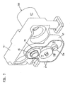
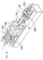
- the injection molding machine has according to Fig. 16 a modular construction with multiple drive groups, which are assigned to the mold closing unit F and partly the injection molding unit S partly. Mold closing unit F and injection molding unit are arranged on the machine base 35.
- the mold clamping unit F has a stationary mold carrier 34 and a movable mold carrier 13. Between the two mold carriers, a mold clamping space R is formed in which molded parts of an injection mold M or an injection mold are accommodated on the stationary mold carrier 34 and on the movable mold carrier 13.
- the mold clamping unit has a lock mechanism C which at the same time constitutes the first drive group 100 for moving the movable mold carrier toward and away from the stationary mold carrier 34.
- a first support element 25 is provided, wherein in "serial closing" also a further support element may be provided. In this serial closing, the movable mold carrier is transferred to the form-fit via the first drive group 100, while the closing force is applied by a separate drive group.
- the second drive group 200 As means for applying the closing force is the second drive group 200, which is used in particular when the first drive group 100 has transferred the movable mold carrier 13 to the positive connection of the injection mold M. If desired, however, the first drive group 100 may be formed with the second drive group 200 combined by one and the same drive group, which may be e.g. especially in a hydraulic solution is possible.
- power transmission means are provided. These power transmission means are the spars 86, which serve at the same time the closing mechanism C and the movable mold carrier 13 as a guide.
- the force transmission element other elements may be provided, such as e.g. so-called “C-brackets", which guide the forces occurring during closing and during injection molding around the mold clamping space R from the stationary mold carrier 34 to the movable mold carrier 13, as is known to the person skilled in the art.
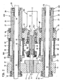
- the injection molding unit S has according to Fig.1 a plasticizing unit P, which has a plasticizing cylinder 11 and a conveyor 12 received in the plasticizing cylinder. At the end, the injection molding unit ends with a nozzle body 52, which has a nozzle orifice 52a, which lies in a spray axis ss ( Fig. 11 . 12 ).
- the plasticizing unit P is detachably fastened to a carrier block 10 arranged movably on the machine base 35 along the axis of injection ss.
- the injection molding unit S further comprises an injection bridge 14 and a metering drive 41, 41 ', 41 "for the conveying means 12 and the plasticizing unit P as the third drive group 300, which can be connected to the injection bridge 14.
- the metering drive serves in particular for rotating the conveying means, since this If a delivery piston is provided here, the third drive group 300 coincides with the injection center 43 of the fifth drive group 500.
- injection means at least one to the injection axis s-s parallel axis drive - usually to achieve a symmetrical force but several drives - provided, which serves as a fifth drive group 500 for relative movement of the conveyor 12 relative to the plasticizing cylinder 11.
- the plasticized material located in front of the conveyor screw is injected into the mold cavity of the injection mold M.
- the fourth drive group 400 is at least one nozzle traveling drive 42 which is parallel to the injection axis s-s. Again, several drives can be provided as in the embodiment.
- the plasticized material injected into the mold cavity has hardened, it is ejected as a molded article via an ejector unit 24, which is arranged on the mold closing side at any desired location within the injection molding machine, but usually in the injection axis s-s.
- the ejector unit 24 can also be designed as a core pull.
- the drive of ejector unit 24 or core pull takes place via a sixth drive group 600.
- a seventh drive group 700 is provided, via which a nozzle needle 51 can be actuated via a linkage 50 in order to close the nozzle orifice 52a in the case of a closure nozzle as required.
- Distributed over the injection molding machine can be arranged multifunction elements. At least one of the drive groups 100, 200, 300, 400, 500, 600, 700 is connected to the injection molding machine via at least one of these multifunction elements.
- the multifunction element serves as an interface for connecting different types of drives. It optionally allows the connection of at least two different drive types, e.g. electromechanical drives, hydraulic drives, pneumatic drives, linear motor drives or electromagnetic drives.
- electromechanical drives, hydraulic drives, pneumatic drives, linear motor drives or electromagnetic drives e.g. electromechanical drives, hydraulic drives, pneumatic drives, linear motor drives or electromagnetic drives.
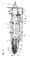
- Fig. 1 shows a purely hydraulic injection molding unit.
- This injection molding unit is partly enlarged in section also in Fig. 2 shown.
- the fifth drive group 500 serves as injection means an injection cylinder 60 with cylinder chamber 61 and 62.
- This injection cylinder is closed by cylinder covers 63 and 64 which slide on the cylinder 27 of a nozzle drive unit of the fourth drive group 400.
- the injection bridge 14 By pressurizing the cylinder chambers 61, 62 with hydraulic medium or pneumatically, the injection bridge 14 'is moved along the spray axis ss, the conveying means 12 being moved axially in the plasticizing cylinder 11 during this movement.
- the plasticizing cylinder 11 is releasably secured to the support block 10, on which the cylinder 27 is fixed.
- the cylinder 27 is coaxially penetrated by bars 31, which also carry the piston 30 for the fourth drive group 400 of the nozzle travel drives.
- bars 31, which also carry the piston 30 for the fourth drive group 400 of the nozzle travel drives are arranged coaxially with each other in the injection cylinder and nozzle drive.
- the injection bridge 14 ' carries centrally a rotation transmission element 46, which is formed together with the injection bridge 14' as a multifunction element for the third drive group 300.
- the rotation transmission element 46 serves to transmit the rotation of a metering drive 41, which serves for the preparation of the material to be processed and this rotates the conveying means designed as a screw conveyor.
- the rotation transmission element 46 is located in a recess 14a 'of the injection bridge 14' and is rotatably supported there via bearings 15 and also set in the axial direction.
- the rotation transmission element 46 has a recess 46a on the rear side, into which the drive shaft 41a of the metering drive 41 engages for operative connection.
- the metering drive is in Fig. 2 a hydraulic rotary motor, instead, can also be an electrically operated high-torque motor as in Fig. 3 be used. Both motors attack insofar at the same recess 46a, which in Fig. 1 is clearly visible.
- a gear housing 47 is now arranged on a portion 46b of the rotation transmission element 46.
- the recess 46a is without function here.
- the section 46b projects out of the injection bridge 14 'to the front, so that there the transmission housing 47 can be coupled with the associated gear.
- the drive takes place via a metering drive 41 '.
- Section 46b makes clear the principle pursued here. Constructively, not only the section 46b is provided for connection of the transmission, but also provided on the injection molding machine, the space, so that the elements of the various types of drive can be accommodated at any time.
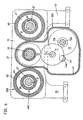
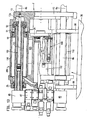
- gear and metering motor 41 'of the third drive group 300 results from the FIGS. 5 to 7 , According to Fig. 6 and 7 the metering motor 41 'drives the pinion 72 with a drive shaft 41a'.
- the pinion 72 is mounted with the axis 72 a in the gear housing and has on the same axis a smaller pinion 72 b, which meshes with the pinion 71.
- the pinion 71 is according to Fig. 5 stored in the transmission housing 47 with its axis 71a.
- the pinion 71 meshes with the pinion 70, according to Fig. 5 is connected to the rotation transmitting member 46.
- the metering motor 41 with its drive shaft 41a must be removed from the recess 46a. Then, the locking mechanism 45, which locks the rotation transmission member 46 to the conveyor 12, must be removed, so that the transmission can be flanged together with servo motor in the section 46b, if necessary.
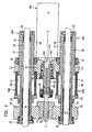
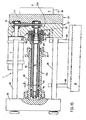
- FIGS. 8 to 10 Another embodiment of the metering drive and especially the injection means 43 show the FIGS. 8 to 10 ,
- the injection bridge 14 is provided as a multi-functional element for the fifth assembly 500 and has a contact surface 14a.
- This contact surface can according to Fig. 8 serve as an injection means 43 formed pressure transmitting element as an investment.
- the pressure transmission element is supported on a support 18. According to Fig. 8 is located the support 18 at one end of the cylinder 27, while the support block at the other end of the cylinder 27 is arranged so that a force frame is formed on the cylinder 27, via which the injection means 43 is supported.
- a hydraulic or pneumatic piston 49 is provided as injection means 43, a hydraulic or pneumatic piston 49.
- This piston is guided in a pot-shaped recess 18 a of the support 18. If the local hydraulic chamber 48 is acted upon, the piston 49 is pressed in the direction of the support block, wherein it transfers its force via the recess 14a on the injection bridge, which transmits this force to the conveyor 12.
- an electric motor is provided, which drives the further drive element 20 via a gear, which is mounted via bearings 15 in the injection bridge.
- a first drive element 19 is provided which is without function in this case. It can be seen that the cylinder 27 only the injection bridge 14 and the support 18 serves as a guide, without further cylinders, as in the Fig. 1 to 7 are interposed.
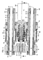
- Fig. 9 differs from Fig. 8 in that an electromechanical drive 16 is provided as the injection means 43, as it is from the older German patent application 197 31 833.9 is known.
- the cup-shaped recess 18a of the support 18 supports a part of the electromechanical spindle drive.
- the cooperating with this non-rotatable part rotatable part of this drive is mounted on the injection bridge 14.
- a threaded tube 16b In the pot-like recess is a threaded tube 16b to lie, which cooperates with a spindle head 16c, wherein the spindle head 16c at the end of a linear movement means 16a is arranged.
- This linear movement means 16a penetrates the pressure transmission element formed as a pressure tube 26 coaxially and is driven via the first drive element 19, wherein the drive via an electric motor of the fifth drive group 500 takes place. Between spindle head 16c and threaded tube 16b planet 16d are arranged.
- the pressure tube 26 which is fixed in the recess 14a of the injection bridge, immersed in any position in the threaded tube 16b, so that the external impression of a piston-cylinder unit results. This contributes to the protection of the drive unit from dirt and allows the introduction of a permanent lubrication.
- Threaded tube 16b and spindle head communicate with each other via planets 16d. Pressure tube 26 and threaded tube 16b are indirectly connected via a thrust bearing member 40.
- the first drive element 19 and the further drive element 20 are arranged coaxially with each other. Be according to Fig. 9 When both drive elements are used, the axial bearing element 21 simultaneously serves as a force transmission element and separating means between the two drive elements, which are driven at different times by their respective drives metering motor 41 "or electric motor of the fifth module 500.
- the axial bearing element 21 simultaneously serves as a force transmission element and separating means between the two drive elements, which are driven at different times by their respective drives metering motor 41 "or electric motor of the fifth module 500.
- Fig. 10 differs from Fig. 9 in that the cylinder 27 is the primary element of a linear motor. As a nozzle drive 42, a secondary element is arranged on the hotm 31. By appropriate loading of the primary element erfotgt a relative movement of the primary element to the secondary element and thus the nozzle travel movement.
- Fig. 2 . 9 and 10 makes it clear that for different types of drive with constant cylinder covers 32,33 only the cylinder must be replaced accordingly. Is applied to the different volumes of hydraulic spaces 61.62 in Fig. 2 If the cylinder were omitted and possibly prepared to be used as a primary element of a linear motor, an exchange of the cylinder 27 is basically no longer necessary.
- the cylinder 27 serves as the cylinder cover 32,33 as a multi-functional element for the fourth assembly 400, which serves either inside as a cylinder for a hydraulic annular piston 30 or as a wall for the secondary element 75 of the linear motor.
- the cylinder can be configured as a multifunctional element for the fifth module 500 and serves as the injection bridge 14, 14 'as a guide or is optionally the piston rod of a hydraulic injection device 43.
- the Figures 11 . 12 show various embodiments of a plasticizing unit with closure nozzle.
- the plasticizing unit P has a plasticizing cylinder 11, in which the conveying means 12 is received.
- the plasticizing unit is releasably secured to the support block 10, wherein when detached the drive mechanism for the closure nozzle remains on the plasticizing cylinder.
- the nozzle needle 51 is controlled via a linkage 50 and a pivot lever 55.
- the nozzle body 52 is connected via a connecting sleeve 53 with the plasticizing cylinder 11.
- a nozzle insert 54 is arranged.
- In the injection axis ss is the nozzle orifice 52a.
- FIG. 11 ends the linkage 50 in one Connection point 50a, with which it can be fixed to a hydraulic piston-cylinder unit.
- a housing wall 80 is provided which is exchanged with the plasticizing cylinder 11.
- the linkage 50 penetrates this housing wall 80.
- this housing wall is used, for example, as a housing of a hollow shaft motor, the electromechanically actuated via a Wälzgewindeantrieb 84, the linkage 50 '.
- the linkage 50 ' is replaced by linkage 50.
- a comparison of the two representations shows that all elements are provided for connecting the hollow shaft motor or another electric motor, so that only linkage and drive group must be replaced, for example, to achieve a conversion to clean room conditions at the customer.
- the movable mold carrier 13 is designed as a multi-functional element for the first and second drive group 100, 200.
- the mold clamping unit is supported by bearing elements 88 on the machine base 35.
- About the guide rails 86 of the locking mechanism C is connected to the stationary mold carrier 34.
- the locking mechanism C moves the movable mold support 13, which is connected in the embodiments with a first support member 25 either via a threaded tube 89 or via the cylinder 110 to an elongated movement unit in the form of a force frame.
- Hydraulic drive groups are controlled by a hydraulic block 87. In the fully hydraulic embodiment according to Fig.
- the movable mold carrier 13 has a recess 13a. At the bottom of this recess, the piston rod 111 of the first assembly 100 is fixed for moving the movable mold carrier 13 to the positive engagement.
- the recess 13a is in this case part of a pressure chamber within the cylinder 110.
- the first drive group 100 is at the same time the piston rod 111 of the device for applying the closing force of the second drive group 200. It carries the piston 90, which has overflow through a valve piston 91st be closed, the movement is limited by a limiting element 92.
- the drive groups are electromechanical. Nevertheless, the hydraulic block 87, the other support member 85, the guide rails 86 and especially the movable mold carrier 13 are maintained. While in Fig. 13 the cylinder 110 of the second assembly 200 for applying the closing force is fixed at the edge of the recess 13 a, serves in Fig. 14 the recess 13a with a contact surface 13b a threaded tube 89 as an investment. This threaded tube communicates with planets 96 which are driven by a spindle head 95. The drive takes place via a drive rod 94, which rotates freely in a pressure tube 93. Externally, the appearance of a piston-cylinder unit also arises during movement. The closing force can be applied in a manner not shown in the drawing, for example by a short-stroke cylinder, which acts on the further supporting element 85.
- Fig. 13 . 14 show the sixth drive group 600 of the ejector unit 24.
- Fig. 13 are arranged around a balancing cylinder 112 around two hydraulic piston-cylinder units which act on the ejector unit 24, which may also be designed as a core pull.
- electromechanical spindle drives can be used either instead of the hydraulic piston-cylinder units or, for example, the surface of the compensating cylinder 112 at the same time used as a primary element of a linear motor, in a graphically not shown manner, a sleeve connected to the ejector 24 may be the secondary element.
- the ejector unit 24 is designed as an independent structural unit, as shown in WO-A 97/12741 is known, the disclosure of which is hereby expressly made the subject of the present application.
- the drive is a hollow shaft motor, which receives in itself the actuating element, which can be used by appropriate rotation transmission elements this ejector unit as unscrewing or as core pull.
- any other ejector can be used, provided that it is ensured that a connection to the movable mold carrier 13 is possible.
- Fig. 15 shows the use of an electromechanical drive unit as a first assembly 100 and a hydraulic unit as a drive group 200.
- the structure corresponds to the structure in the earlier patent application 197 50 057.9 ,
- the locking mechanism C drives the drive rod 94 via a belt drive 81.
- the drive rod 94 terminates at the spindle head 95 which is connected via planet 96 with a threaded tube 89 in connection.
- the threaded tube 89 is closed at the end by a closure element 97, so that here again gives the impression of a piston-cylinder unit, since the threaded elements are externally invisible.
- the movable mold carrier is divided in two into the parts 13 ', 13 "in order to be able to receive the belt drive 81.
- the first drive group 100 brings the injection mold M into positive engagement This can be done at any time during the movement by the switching chamber 98 is pressurized, so that the further support member 85, which here is a piston, the bearing sleeve 83 in Fig. 15 presses to the left.
- the movable mold carrier 13 ', 13 "up to any gap between the mold halves or until moved to positive engagement, which adjusts to each other at the latest when planting the two halves of the mold force and thus deformation, depending on the balance of forces between the switching chamber 98 and the pressure chamber 99 to an earlier or later reduction of the distance a to the system of pressure tube 93rd on the spindle head 95 leads. This system prevents further rotation.
- the pressure tube 93 is connected to the further support element 85 designed as a piston.
- the position of the pressure tube can be influenced by the pressure in the switching chamber 98.
Landscapes
- Engineering & Computer Science (AREA)
- Manufacturing & Machinery (AREA)
- Mechanical Engineering (AREA)
- Injection Moulding Of Plastics Or The Like (AREA)
- Moulds For Moulding Plastics Or The Like (AREA)
Applications Claiming Priority (3)
| Application Number | Priority Date | Filing Date | Title |
|---|---|---|---|
| DE19847298 | 1998-10-14 | ||
| DE19847298A DE19847298C2 (de) | 1998-10-14 | 1998-10-14 | Spritzgießmaschine mit einem mehrere Antriebsgruppen umfassenden modularen Aufbau |
| PCT/EP1999/007582 WO2000021729A1 (de) | 1998-10-14 | 1999-10-09 | Spritzgiessmaschine mit einem mehrere antriebsgruppen umfassenden modularen aufbau |
Publications (3)
| Publication Number | Publication Date |
|---|---|
| EP1121237A1 EP1121237A1 (de) | 2001-08-08 |
| EP1121237B1 EP1121237B1 (de) | 2002-12-11 |
| EP1121237B2 true EP1121237B2 (de) | 2010-08-04 |
Family
ID=7884405
Family Applications (1)
| Application Number | Title | Priority Date | Filing Date |
|---|---|---|---|
| EP99952546A Expired - Lifetime EP1121237B2 (de) | 1998-10-14 | 1999-10-09 | Spritzgiessmaschine mit einem mehrere antriebsgruppen umfassenden modularen aufbau |
Country Status (7)
| Country | Link |
|---|---|
| US (1) | US6517337B1 (ja) |
| EP (1) | EP1121237B2 (ja) |
| JP (1) | JP2002527256A (ja) |
| AT (1) | ATE229422T1 (ja) |
| CA (1) | CA2347458C (ja) |
| DE (2) | DE19847298C2 (ja) |
| WO (1) | WO2000021729A1 (ja) |
Families Citing this family (19)
| Publication number | Priority date | Publication date | Assignee | Title |
|---|---|---|---|---|
| DE10022192A1 (de) * | 2000-05-03 | 2001-11-15 | Mannesmann Ag | Einrichtung zum Entfernen von Spritzgießteilen |
| WO2002064347A1 (de) * | 2001-02-15 | 2002-08-22 | Mannesmann Plastics Machinery Gmbh | Schliesseinrichtung in einer spritzgiessmaschine für kunststoffe |
| AT5362U1 (de) * | 2001-05-11 | 2002-06-25 | Engel Gmbh Maschbau | Einrichtung zum spritzgiessen von kunststoff |
| EP1582332B1 (en) | 2002-10-31 | 2011-02-02 | Sumitomo Heavy Industries, Ltd. | Forming machine and method of controlling the same |
| DE10309906B3 (de) * | 2003-02-25 | 2004-06-09 | Karl Hehl | Formschließeinheit für eine Spritzgießmaschine zur Verarbeitung von Kunststoffen |
| DE102004033690A1 (de) * | 2004-07-09 | 2006-02-16 | Demag Ergotech Gmbh | Spritzgiessmaschine |
| DE102004057164A1 (de) * | 2004-11-26 | 2006-06-01 | Krauss-Maffei Kunststofftechnik Gmbh | Spritzgießmaschine |
| DE202005021060U1 (de) * | 2005-09-14 | 2007-01-18 | Siemens Ag | Spritzgießmaschine |
| US7772266B2 (en) | 2006-02-15 | 2010-08-10 | Dendreon Corporation | Small-molecule modulators of TRP-P8 activity |
| US20070296281A1 (en) * | 2006-06-07 | 2007-12-27 | Husky Injection Molding Systems Ltd. | Electrical motor |
| US20070296121A1 (en) * | 2006-06-07 | 2007-12-27 | Husky Injection Molding Systems Ltd. | Molding-system drive |
| US7695266B2 (en) * | 2006-11-02 | 2010-04-13 | Husky Injection Molding Systems Ltd. | Molding structure |
| DE102007042643A1 (de) | 2007-09-07 | 2009-04-02 | Siemens Ag | Verfahren zum Betrieb einer Einspritzeinrichtung für eine Spritzgießmaschine, Einspritzeinrichtung sowie Spritzgießmaschine mit einer derartigen Einspritzeinrichtung |
| GB2478732B (en) | 2010-03-15 | 2014-08-20 | Kraft Foods R & D Inc | Improvements in injection moulding |
| CN102211383B (zh) * | 2010-04-01 | 2013-11-06 | 永高股份有限公司 | 塑料模具二次滑块抽芯机构 |
| DE102010046275A1 (de) | 2010-09-22 | 2012-03-22 | Netstal-Maschinen Ag | Universelle Hilfssteuerung für eine Spritzgießmaschine |
| JP5980865B2 (ja) * | 2014-09-11 | 2016-08-31 | ファナック株式会社 | 射出成形機 |
| DE102016205554B4 (de) * | 2016-04-04 | 2022-02-24 | Rekers Gmbh Maschinen- Und Anlagenbau | Ziehdornvorrichtung für eine Steinformmaschine, Steinformmaschine und Verfahren zur Herstellung von Formsteinen |
| JP6867978B2 (ja) * | 2018-06-13 | 2021-05-12 | 日精樹脂工業株式会社 | 射出成形機及びその成形方法 |
Citations (1)
| Publication number | Priority date | Publication date | Assignee | Title |
|---|---|---|---|---|
| DE2247386A1 (de) † | 1972-09-27 | 1974-03-28 | Demag Ag | Vorrichtung fuer den antrieb der schnecke einer schneckenspritzgiessmaschine |
Family Cites Families (5)
| Publication number | Priority date | Publication date | Assignee | Title |
|---|---|---|---|---|
| ATE157043T1 (de) * | 1992-06-23 | 1997-09-15 | Battenfeld Kunststoffmasch | Spritzaggregat für spritzgiessmaschinen |
| DE19536565C2 (de) * | 1995-10-02 | 1998-07-16 | Karl Hehl | Spritzgießmaschine zur Verarbeitung plastifizierbarer Massen |
| DE19536567C2 (de) | 1995-10-02 | 1998-12-17 | Karl Hehl | Formschließeinheit mit einer Einrichtung zur Behandlung und/oder Entfernung von Spritzteilen |
| DE19731833C1 (de) * | 1997-07-24 | 1999-01-14 | Karl Hehl | Spritzgießeinheit für eine Spritzgießmaschine |
| DE19750057C2 (de) | 1997-11-12 | 2000-08-03 | Karl Hehl | Formschließeinheit für eine Spritzgießmaschine |
-
1998
- 1998-10-14 DE DE19847298A patent/DE19847298C2/de not_active Expired - Fee Related
-
1999
- 1999-10-09 JP JP2000575673A patent/JP2002527256A/ja active Pending
- 1999-10-09 AT AT99952546T patent/ATE229422T1/de active
- 1999-10-09 WO PCT/EP1999/007582 patent/WO2000021729A1/de active IP Right Grant
- 1999-10-09 DE DE59903783T patent/DE59903783D1/de not_active Expired - Lifetime
- 1999-10-09 EP EP99952546A patent/EP1121237B2/de not_active Expired - Lifetime
- 1999-10-09 CA CA002347458A patent/CA2347458C/en not_active Expired - Fee Related
- 1999-10-09 US US09/807,395 patent/US6517337B1/en not_active Expired - Lifetime
Patent Citations (1)
| Publication number | Priority date | Publication date | Assignee | Title |
|---|---|---|---|---|
| DE2247386A1 (de) † | 1972-09-27 | 1974-03-28 | Demag Ag | Vorrichtung fuer den antrieb der schnecke einer schneckenspritzgiessmaschine |
Also Published As
| Publication number | Publication date |
|---|---|
| ATE229422T1 (de) | 2002-12-15 |
| EP1121237A1 (de) | 2001-08-08 |
| DE59903783D1 (de) | 2003-01-23 |
| CA2347458A1 (en) | 2000-04-20 |
| DE19847298A1 (de) | 2000-04-27 |
| EP1121237B1 (de) | 2002-12-11 |
| JP2002527256A (ja) | 2002-08-27 |
| CA2347458C (en) | 2008-11-25 |
| DE19847298C2 (de) | 2000-11-02 |
| WO2000021729A1 (de) | 2000-04-20 |
| US6517337B1 (en) | 2003-02-11 |
Similar Documents
| Publication | Publication Date | Title |
|---|---|---|
| EP1121237B2 (de) | Spritzgiessmaschine mit einem mehrere antriebsgruppen umfassenden modularen aufbau | |
| EP1768828B1 (de) | Spritzgiessmaschine | |
| DE19920626C2 (de) | Spritzgießmaschine zur Verarbeitung von Kunststoffen | |
| DE2113414A1 (de) | Schliess-,Verriegelungs- und Vorspann-Vorrichtung fuer Giessformen | |
| EP1097035B1 (de) | Spritzgiesseinheit für eine spritzgiessmaschine | |
| EP1802441B1 (de) | Schliesseinheit für eine spritzgiessmaschine mit etagenwerkzeug | |
| EP1339537B1 (de) | Einspritzeinheit für eine spritzgiessmaschine | |
| EP0508277A2 (de) | Verschiebe- und/oder Stellkraft-Antriebsvorrichtung für Spritzgiessmaschinen | |
| WO1997007960A1 (de) | Spritzgiessmaschine mit integriertem heisskanalsystem | |
| EP0576837B1 (de) | Spritzgiessmaschine mit Etagenwerkzeug | |
| EP0107778B1 (de) | Verfahren und Vorrichtung zur Verarbeitung einer plastifizierbaren Masse | |
| EP0585671B1 (de) | Auswerfereinheit für Spritzgiessmaschinen | |
| DE102021130687B3 (de) | Mehrkomponenten-Spritzgießmaschine | |
| DE102017223822A1 (de) | Formschließeinheit für eine Spritzgießmaschine sowie Verfahren zum Verriegeln eines Kraftübertragungselements | |
| EP0639444B1 (de) | Einspritzaggregat | |
| EP3710222B1 (de) | Formschliesseinheit für eine spritzgiessmaschine sowie verfahren zum verriegeln eines kraftübertragungselements | |
| EP1848577B1 (de) | Spritzgiessmaschine zur verarbeitung von kunststoffen | |
| DE19536567A1 (de) | Formschließeinheit mit einer Einrichtung zur Behandlung und/oder Entfernung von Spritzteilen | |
| DE19605747C2 (de) | Antriebseinheit für Plastifizier- und Einspritzeinheiten von Kunststoff-Spritzgießmaschinen | |
| DE19535081C2 (de) | Zwei-Platten-Spritzgießmaschine | |
| DE19514346C1 (de) | Vorrichtung zur Schmiermittelversorgung einer Spritzgießmaschine | |
| EP2719517B1 (de) | Spritzgiessmaschine | |
| EP3959058B1 (de) | Spritzgiesseinheit für eine spritzgiessmaschine zur verarbeitung von kunststoffen | |
| DE10040322B4 (de) | Kunststoffspritzgießmaschine und Antriebsvorrichtung für eine Kunststoffspritzgießmaschine | |
| DE19531335C2 (de) | Spritzgießeinheit für eine Spritzgießmaschine |
Legal Events
| Date | Code | Title | Description |
|---|---|---|---|
| PUAI | Public reference made under article 153(3) epc to a published international application that has entered the european phase |
Free format text: ORIGINAL CODE: 0009012 |
|
| 17P | Request for examination filed |
Effective date: 20010320 |
|
| AK | Designated contracting states |
Kind code of ref document: A1 Designated state(s): AT BE CH CY DE DK ES FI FR GB GR IE IT LI LU MC NL PT SE |
|
| GRAG | Despatch of communication of intention to grant |
Free format text: ORIGINAL CODE: EPIDOS AGRA |
|
| 17Q | First examination report despatched |
Effective date: 20020102 |
|
| GRAG | Despatch of communication of intention to grant |
Free format text: ORIGINAL CODE: EPIDOS AGRA |
|
| GRAH | Despatch of communication of intention to grant a patent |
Free format text: ORIGINAL CODE: EPIDOS IGRA |
|
| GRAH | Despatch of communication of intention to grant a patent |
Free format text: ORIGINAL CODE: EPIDOS IGRA |
|
| GRAA | (expected) grant |
Free format text: ORIGINAL CODE: 0009210 |
|
| AK | Designated contracting states |
Kind code of ref document: B1 Designated state(s): AT CH DE FR GB IT LI |
|
| REF | Corresponds to: |
Ref document number: 229422 Country of ref document: AT Date of ref document: 20021215 Kind code of ref document: T |
|
| REG | Reference to a national code |
Ref country code: GB Ref legal event code: FG4D Free format text: NOT ENGLISH |
|
| REG | Reference to a national code |
Ref country code: CH Ref legal event code: EP |
|
| REG | Reference to a national code |
Ref country code: CH Ref legal event code: NV Representative=s name: LUCHS & PARTNER PATENTANWAELTE |
|
| REF | Corresponds to: |
Ref document number: 59903783 Country of ref document: DE Date of ref document: 20030123 |
|
| GBT | Gb: translation of ep patent filed (gb section 77(6)(a)/1977) |
Effective date: 20030307 |
|
| ET | Fr: translation filed | ||
| PLBQ | Unpublished change to opponent data |
Free format text: ORIGINAL CODE: EPIDOS OPPO |
|
| PLBI | Opposition filed |
Free format text: ORIGINAL CODE: 0009260 |
|
| 26 | Opposition filed |
Opponent name: ENGEL AUSTRIA GMBH Effective date: 20030905 |
|
| PLAX | Notice of opposition and request to file observation + time limit sent |
Free format text: ORIGINAL CODE: EPIDOSNOBS2 |
|
| PLAX | Notice of opposition and request to file observation + time limit sent |
Free format text: ORIGINAL CODE: EPIDOSNOBS2 |
|
| PLAX | Notice of opposition and request to file observation + time limit sent |
Free format text: ORIGINAL CODE: EPIDOSNOBS2 |
|
| PLBB | Reply of patent proprietor to notice(s) of opposition received |
Free format text: ORIGINAL CODE: EPIDOSNOBS3 |
|
| PLAY | Examination report in opposition despatched + time limit |
Free format text: ORIGINAL CODE: EPIDOSNORE2 |
|
| PLBC | Reply to examination report in opposition received |
Free format text: ORIGINAL CODE: EPIDOSNORE3 |
|
| PGFP | Annual fee paid to national office [announced via postgrant information from national office to epo] |
Ref country code: GB Payment date: 20061024 Year of fee payment: 8 |
|
| PLAB | Opposition data, opponent's data or that of the opponent's representative modified |
Free format text: ORIGINAL CODE: 0009299OPPO |
|
| R26 | Opposition filed (corrected) |
Opponent name: ENGEL AUSTRIA GMBH Effective date: 20030905 |
|
| APBP | Date of receipt of notice of appeal recorded |
Free format text: ORIGINAL CODE: EPIDOSNNOA2O |
|
| APAH | Appeal reference modified |
Free format text: ORIGINAL CODE: EPIDOSCREFNO |
|
| APBQ | Date of receipt of statement of grounds of appeal recorded |
Free format text: ORIGINAL CODE: EPIDOSNNOA3O |
|
| GBPC | Gb: european patent ceased through non-payment of renewal fee |
Effective date: 20071009 |
|
| PG25 | Lapsed in a contracting state [announced via postgrant information from national office to epo] |
Ref country code: GB Free format text: LAPSE BECAUSE OF NON-PAYMENT OF DUE FEES Effective date: 20071009 |
|
| APBU | Appeal procedure closed |
Free format text: ORIGINAL CODE: EPIDOSNNOA9O |
|
| PUAH | Patent maintained in amended form |
Free format text: ORIGINAL CODE: 0009272 |
|
| STAA | Information on the status of an ep patent application or granted ep patent |
Free format text: STATUS: PATENT MAINTAINED AS AMENDED |
|
| 27A | Patent maintained in amended form |
Effective date: 20100804 |
|
| AK | Designated contracting states |
Kind code of ref document: B2 Designated state(s): AT CH DE FR GB IT LI |
|
| REG | Reference to a national code |
Ref country code: CH Ref legal event code: AEN Free format text: AUFRECHTERHALTUNG DES PATENTES IN GEAENDERTER FORM |
|
| PGFP | Annual fee paid to national office [announced via postgrant information from national office to epo] |
Ref country code: FR Payment date: 20111103 Year of fee payment: 13 |
|
| REG | Reference to a national code |
Ref country code: FR Ref legal event code: ST Effective date: 20130628 |
|
| PG25 | Lapsed in a contracting state [announced via postgrant information from national office to epo] |
Ref country code: FR Free format text: LAPSE BECAUSE OF NON-PAYMENT OF DUE FEES Effective date: 20121031 |
|
| PGFP | Annual fee paid to national office [announced via postgrant information from national office to epo] |
Ref country code: IT Payment date: 20131030 Year of fee payment: 15 |
|
| REG | Reference to a national code |
Ref country code: DE Ref legal event code: R082 Ref document number: 59903783 Country of ref document: DE Representative=s name: PATENTANWAELTE REINHARDT & POHLMANN PARTNERSCH, DE |
|
| REG | Reference to a national code |
Ref country code: DE Ref legal event code: R082 Ref document number: 59903783 Country of ref document: DE Representative=s name: RPK PATENTANWAELTE REINHARDT, POHLMANN UND KAU, DE Effective date: 20140731 Ref country code: DE Ref legal event code: R082 Ref document number: 59903783 Country of ref document: DE Representative=s name: PATENTANWAELTE REINHARDT & POHLMANN PARTNERSCH, DE Effective date: 20140731 Ref country code: DE Ref legal event code: R081 Ref document number: 59903783 Country of ref document: DE Owner name: KEINATH, RENATE, DE Free format text: FORMER OWNER: HEHL, KARL, 72290 LOSSBURG, VERSTORBEN, DE Effective date: 20140731 |
|
| PG25 | Lapsed in a contracting state [announced via postgrant information from national office to epo] |
Ref country code: IT Free format text: LAPSE BECAUSE OF NON-PAYMENT OF DUE FEES Effective date: 20141009 |
|
| PGFP | Annual fee paid to national office [announced via postgrant information from national office to epo] |
Ref country code: CH Payment date: 20151026 Year of fee payment: 17 |
|
| PGFP | Annual fee paid to national office [announced via postgrant information from national office to epo] |
Ref country code: DE Payment date: 20160805 Year of fee payment: 18 |
|
| PGFP | Annual fee paid to national office [announced via postgrant information from national office to epo] |
Ref country code: AT Payment date: 20161024 Year of fee payment: 18 |
|
| REG | Reference to a national code |
Ref country code: CH Ref legal event code: PL |
|
| PG25 | Lapsed in a contracting state [announced via postgrant information from national office to epo] |
Ref country code: CH Free format text: LAPSE BECAUSE OF NON-PAYMENT OF DUE FEES Effective date: 20161031 Ref country code: LI Free format text: LAPSE BECAUSE OF NON-PAYMENT OF DUE FEES Effective date: 20161031 |
|
| REG | Reference to a national code |
Ref country code: DE Ref legal event code: R119 Ref document number: 59903783 Country of ref document: DE |
|
| REG | Reference to a national code |
Ref country code: AT Ref legal event code: MM01 Ref document number: 229422 Country of ref document: AT Kind code of ref document: T Effective date: 20171009 |
|
| PG25 | Lapsed in a contracting state [announced via postgrant information from national office to epo] |
Ref country code: DE Free format text: LAPSE BECAUSE OF NON-PAYMENT OF DUE FEES Effective date: 20180501 |
|
| PG25 | Lapsed in a contracting state [announced via postgrant information from national office to epo] |
Ref country code: AT Free format text: LAPSE BECAUSE OF NON-PAYMENT OF DUE FEES Effective date: 20171009 |