EP1121237B2 - Injection molding machine having a modular construction which comprises a plurality of drive groups - Google Patents
Injection molding machine having a modular construction which comprises a plurality of drive groups Download PDFInfo
- Publication number
- EP1121237B2 EP1121237B2 EP99952546A EP99952546A EP1121237B2 EP 1121237 B2 EP1121237 B2 EP 1121237B2 EP 99952546 A EP99952546 A EP 99952546A EP 99952546 A EP99952546 A EP 99952546A EP 1121237 B2 EP1121237 B2 EP 1121237B2
- Authority
- EP
- European Patent Office
- Prior art keywords
- drive
- injection
- injection moulding
- moulding machine
- machine according
- Prior art date
- Legal status (The legal status is an assumption and is not a legal conclusion. Google has not performed a legal analysis and makes no representation as to the accuracy of the status listed.)
- Expired - Lifetime
Links
Images


Classifications
-
- B—PERFORMING OPERATIONS; TRANSPORTING
- B29—WORKING OF PLASTICS; WORKING OF SUBSTANCES IN A PLASTIC STATE IN GENERAL
- B29C—SHAPING OR JOINING OF PLASTICS; SHAPING OF MATERIAL IN A PLASTIC STATE, NOT OTHERWISE PROVIDED FOR; AFTER-TREATMENT OF THE SHAPED PRODUCTS, e.g. REPAIRING
- B29C45/00—Injection moulding, i.e. forcing the required volume of moulding material through a nozzle into a closed mould; Apparatus therefor
- B29C45/17—Component parts, details or accessories; Auxiliary operations
- B29C45/46—Means for plasticising or homogenising the moulding material or forcing it into the mould
- B29C45/47—Means for plasticising or homogenising the moulding material or forcing it into the mould using screws
- B29C45/50—Axially movable screw
- B29C45/5008—Drive means therefor
-
- B—PERFORMING OPERATIONS; TRANSPORTING
- B29—WORKING OF PLASTICS; WORKING OF SUBSTANCES IN A PLASTIC STATE IN GENERAL
- B29C—SHAPING OR JOINING OF PLASTICS; SHAPING OF MATERIAL IN A PLASTIC STATE, NOT OTHERWISE PROVIDED FOR; AFTER-TREATMENT OF THE SHAPED PRODUCTS, e.g. REPAIRING
- B29C45/00—Injection moulding, i.e. forcing the required volume of moulding material through a nozzle into a closed mould; Apparatus therefor
- B29C45/03—Injection moulding apparatus
- B29C45/07—Injection moulding apparatus using movable injection units
-
- B—PERFORMING OPERATIONS; TRANSPORTING
- B29—WORKING OF PLASTICS; WORKING OF SUBSTANCES IN A PLASTIC STATE IN GENERAL
- B29C—SHAPING OR JOINING OF PLASTICS; SHAPING OF MATERIAL IN A PLASTIC STATE, NOT OTHERWISE PROVIDED FOR; AFTER-TREATMENT OF THE SHAPED PRODUCTS, e.g. REPAIRING
- B29C45/00—Injection moulding, i.e. forcing the required volume of moulding material through a nozzle into a closed mould; Apparatus therefor
- B29C45/17—Component parts, details or accessories; Auxiliary operations
- B29C45/20—Injection nozzles
- B29C45/23—Feed stopping equipment
- B29C45/231—Needle valve systems therefor
-
- B—PERFORMING OPERATIONS; TRANSPORTING
- B29—WORKING OF PLASTICS; WORKING OF SUBSTANCES IN A PLASTIC STATE IN GENERAL
- B29C—SHAPING OR JOINING OF PLASTICS; SHAPING OF MATERIAL IN A PLASTIC STATE, NOT OTHERWISE PROVIDED FOR; AFTER-TREATMENT OF THE SHAPED PRODUCTS, e.g. REPAIRING
- B29C45/00—Injection moulding, i.e. forcing the required volume of moulding material through a nozzle into a closed mould; Apparatus therefor
- B29C45/17—Component parts, details or accessories; Auxiliary operations
- B29C45/40—Removing or ejecting moulded articles
- B29C45/4005—Ejector constructions; Ejector operating mechanisms
-
- B—PERFORMING OPERATIONS; TRANSPORTING
- B29—WORKING OF PLASTICS; WORKING OF SUBSTANCES IN A PLASTIC STATE IN GENERAL
- B29C—SHAPING OR JOINING OF PLASTICS; SHAPING OF MATERIAL IN A PLASTIC STATE, NOT OTHERWISE PROVIDED FOR; AFTER-TREATMENT OF THE SHAPED PRODUCTS, e.g. REPAIRING
- B29C45/00—Injection moulding, i.e. forcing the required volume of moulding material through a nozzle into a closed mould; Apparatus therefor
- B29C45/17—Component parts, details or accessories; Auxiliary operations
- B29C45/64—Mould opening, closing or clamping devices
- B29C45/68—Mould opening, closing or clamping devices hydro-mechanical
Definitions
- the invention relates to an injection molding machine for processing plastics and other plasticizable materials such as ceramic or powdery masses with a modular structure comprising a plurality of drive groups according to the preamble of claim 1.
- the present invention seeks to provide in an injection molding machine of the type mentioned the structural requirements for increased modularity using largely identical components.
- a rotation transmission element can be provided in the injection bridge, which is provided both for the fact that a rotary motor is connected at the back or at another point a drive wheel can be set, so that via a transmission of this element can be controlled. For all drives while sufficient space is provided on the injection molding machine.
- injection bridge structural elements can be provided, which are even passive depending on the type of drive and are not needed at all, but on the other hand create the opportunity; easy to change the drive.
- the space required for the various drive types can be obtained by allowing these components, which are required for the various types of drive, to be combined in the smallest possible space.
- the movable mold carrier may be formed so; that both electromechanical drives and hydraulic or pneumatic drives can be connected to the same components. It should not be underestimated that the component must be prepared so far for the different requirements, which must be ensured for the hydraulic tightness as well as for the electromechanical drive, the introduction of force.
- the injection molding machine serves, for example, as a plastic injection molding machine for the processing of plasticizable materials such as plastics, powdery or ceramic materials.
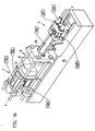
- the injection molding machine has according to Fig. 16 a modular construction with multiple drive groups, which are assigned to the mold closing unit F and partly the injection molding unit S partly. Mold closing unit F and injection molding unit are arranged on the machine base 35.
- the mold clamping unit F has a stationary mold carrier 34 and a movable mold carrier 13. Between the two mold carriers, a mold clamping space R is formed in which molded parts of an injection mold M or an injection mold are accommodated on the stationary mold carrier 34 and on the movable mold carrier 13.
- the mold clamping unit has a lock mechanism C which at the same time constitutes the first drive group 100 for moving the movable mold carrier toward and away from the stationary mold carrier 34.
- a first support element 25 is provided, wherein in "serial closing" also a further support element may be provided. In this serial closing, the movable mold carrier is transferred to the form-fit via the first drive group 100, while the closing force is applied by a separate drive group.
- the second drive group 200 As means for applying the closing force is the second drive group 200, which is used in particular when the first drive group 100 has transferred the movable mold carrier 13 to the positive connection of the injection mold M. If desired, however, the first drive group 100 may be formed with the second drive group 200 combined by one and the same drive group, which may be e.g. especially in a hydraulic solution is possible.
- power transmission means are provided. These power transmission means are the spars 86, which serve at the same time the closing mechanism C and the movable mold carrier 13 as a guide.
- the force transmission element other elements may be provided, such as e.g. so-called “C-brackets", which guide the forces occurring during closing and during injection molding around the mold clamping space R from the stationary mold carrier 34 to the movable mold carrier 13, as is known to the person skilled in the art.
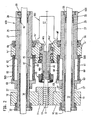
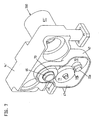
- the injection molding unit S has according to Fig.1 a plasticizing unit P, which has a plasticizing cylinder 11 and a conveyor 12 received in the plasticizing cylinder. At the end, the injection molding unit ends with a nozzle body 52, which has a nozzle orifice 52a, which lies in a spray axis ss ( Fig. 11 . 12 ).
- the plasticizing unit P is detachably fastened to a carrier block 10 arranged movably on the machine base 35 along the axis of injection ss.
- the injection molding unit S further comprises an injection bridge 14 and a metering drive 41, 41 ', 41 "for the conveying means 12 and the plasticizing unit P as the third drive group 300, which can be connected to the injection bridge 14.
- the metering drive serves in particular for rotating the conveying means, since this If a delivery piston is provided here, the third drive group 300 coincides with the injection center 43 of the fifth drive group 500.
- injection means at least one to the injection axis s-s parallel axis drive - usually to achieve a symmetrical force but several drives - provided, which serves as a fifth drive group 500 for relative movement of the conveyor 12 relative to the plasticizing cylinder 11.
- the plasticized material located in front of the conveyor screw is injected into the mold cavity of the injection mold M.
- the fourth drive group 400 is at least one nozzle traveling drive 42 which is parallel to the injection axis s-s. Again, several drives can be provided as in the embodiment.
- the plasticized material injected into the mold cavity has hardened, it is ejected as a molded article via an ejector unit 24, which is arranged on the mold closing side at any desired location within the injection molding machine, but usually in the injection axis s-s.
- the ejector unit 24 can also be designed as a core pull.
- the drive of ejector unit 24 or core pull takes place via a sixth drive group 600.
- a seventh drive group 700 is provided, via which a nozzle needle 51 can be actuated via a linkage 50 in order to close the nozzle orifice 52a in the case of a closure nozzle as required.
- Distributed over the injection molding machine can be arranged multifunction elements. At least one of the drive groups 100, 200, 300, 400, 500, 600, 700 is connected to the injection molding machine via at least one of these multifunction elements.
- the multifunction element serves as an interface for connecting different types of drives. It optionally allows the connection of at least two different drive types, e.g. electromechanical drives, hydraulic drives, pneumatic drives, linear motor drives or electromagnetic drives.
- electromechanical drives, hydraulic drives, pneumatic drives, linear motor drives or electromagnetic drives e.g. electromechanical drives, hydraulic drives, pneumatic drives, linear motor drives or electromagnetic drives.
- Fig. 1 shows a purely hydraulic injection molding unit.
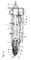
- This injection molding unit is partly enlarged in section also in Fig. 2 shown.
- the fifth drive group 500 serves as injection means an injection cylinder 60 with cylinder chamber 61 and 62.
- This injection cylinder is closed by cylinder covers 63 and 64 which slide on the cylinder 27 of a nozzle drive unit of the fourth drive group 400.
- the injection bridge 14 By pressurizing the cylinder chambers 61, 62 with hydraulic medium or pneumatically, the injection bridge 14 'is moved along the spray axis ss, the conveying means 12 being moved axially in the plasticizing cylinder 11 during this movement.
- the plasticizing cylinder 11 is releasably secured to the support block 10, on which the cylinder 27 is fixed.
- the cylinder 27 is coaxially penetrated by bars 31, which also carry the piston 30 for the fourth drive group 400 of the nozzle travel drives.
- bars 31, which also carry the piston 30 for the fourth drive group 400 of the nozzle travel drives are arranged coaxially with each other in the injection cylinder and nozzle drive.
- the injection bridge 14 ' carries centrally a rotation transmission element 46, which is formed together with the injection bridge 14' as a multifunction element for the third drive group 300.
- the rotation transmission element 46 serves to transmit the rotation of a metering drive 41, which serves for the preparation of the material to be processed and this rotates the conveying means designed as a screw conveyor.
- the rotation transmission element 46 is located in a recess 14a 'of the injection bridge 14' and is rotatably supported there via bearings 15 and also set in the axial direction.
- the rotation transmission element 46 has a recess 46a on the rear side, into which the drive shaft 41a of the metering drive 41 engages for operative connection.
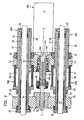
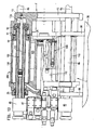
- the metering drive is in Fig. 2 a hydraulic rotary motor, instead, can also be an electrically operated high-torque motor as in Fig. 3 be used. Both motors attack insofar at the same recess 46a, which in Fig. 1 is clearly visible.
- a gear housing 47 is now arranged on a portion 46b of the rotation transmission element 46.
- the recess 46a is without function here.
- the section 46b projects out of the injection bridge 14 'to the front, so that there the transmission housing 47 can be coupled with the associated gear.
- the drive takes place via a metering drive 41 '.
- Section 46b makes clear the principle pursued here. Constructively, not only the section 46b is provided for connection of the transmission, but also provided on the injection molding machine, the space, so that the elements of the various types of drive can be accommodated at any time.
- gear and metering motor 41 'of the third drive group 300 results from the FIGS. 5 to 7 , According to Fig. 6 and 7 the metering motor 41 'drives the pinion 72 with a drive shaft 41a'.
- the pinion 72 is mounted with the axis 72 a in the gear housing and has on the same axis a smaller pinion 72 b, which meshes with the pinion 71.
- the pinion 71 is according to Fig. 5 stored in the transmission housing 47 with its axis 71a.
- the pinion 71 meshes with the pinion 70, according to Fig. 5 is connected to the rotation transmitting member 46.
- the metering motor 41 with its drive shaft 41a must be removed from the recess 46a. Then, the locking mechanism 45, which locks the rotation transmission member 46 to the conveyor 12, must be removed, so that the transmission can be flanged together with servo motor in the section 46b, if necessary.
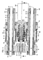
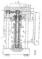
- FIGS. 8 to 10 Another embodiment of the metering drive and especially the injection means 43 show the FIGS. 8 to 10 ,
- the injection bridge 14 is provided as a multi-functional element for the fifth assembly 500 and has a contact surface 14a.
- This contact surface can according to Fig. 8 serve as an injection means 43 formed pressure transmitting element as an investment.
- the pressure transmission element is supported on a support 18. According to Fig. 8 is located the support 18 at one end of the cylinder 27, while the support block at the other end of the cylinder 27 is arranged so that a force frame is formed on the cylinder 27, via which the injection means 43 is supported.
- a hydraulic or pneumatic piston 49 is provided as injection means 43, a hydraulic or pneumatic piston 49.
- This piston is guided in a pot-shaped recess 18 a of the support 18. If the local hydraulic chamber 48 is acted upon, the piston 49 is pressed in the direction of the support block, wherein it transfers its force via the recess 14a on the injection bridge, which transmits this force to the conveyor 12.
- an electric motor is provided, which drives the further drive element 20 via a gear, which is mounted via bearings 15 in the injection bridge.
- a first drive element 19 is provided which is without function in this case. It can be seen that the cylinder 27 only the injection bridge 14 and the support 18 serves as a guide, without further cylinders, as in the Fig. 1 to 7 are interposed.
- Fig. 9 differs from Fig. 8 in that an electromechanical drive 16 is provided as the injection means 43, as it is from the older German patent application 197 31 833.9 is known.
- the cup-shaped recess 18a of the support 18 supports a part of the electromechanical spindle drive.
- the cooperating with this non-rotatable part rotatable part of this drive is mounted on the injection bridge 14.
- a threaded tube 16b In the pot-like recess is a threaded tube 16b to lie, which cooperates with a spindle head 16c, wherein the spindle head 16c at the end of a linear movement means 16a is arranged.
- This linear movement means 16a penetrates the pressure transmission element formed as a pressure tube 26 coaxially and is driven via the first drive element 19, wherein the drive via an electric motor of the fifth drive group 500 takes place. Between spindle head 16c and threaded tube 16b planet 16d are arranged.
- the pressure tube 26 which is fixed in the recess 14a of the injection bridge, immersed in any position in the threaded tube 16b, so that the external impression of a piston-cylinder unit results. This contributes to the protection of the drive unit from dirt and allows the introduction of a permanent lubrication.
- Threaded tube 16b and spindle head communicate with each other via planets 16d. Pressure tube 26 and threaded tube 16b are indirectly connected via a thrust bearing member 40.
- the first drive element 19 and the further drive element 20 are arranged coaxially with each other. Be according to Fig. 9 When both drive elements are used, the axial bearing element 21 simultaneously serves as a force transmission element and separating means between the two drive elements, which are driven at different times by their respective drives metering motor 41 "or electric motor of the fifth module 500.
- the axial bearing element 21 simultaneously serves as a force transmission element and separating means between the two drive elements, which are driven at different times by their respective drives metering motor 41 "or electric motor of the fifth module 500.
- Fig. 10 differs from Fig. 9 in that the cylinder 27 is the primary element of a linear motor. As a nozzle drive 42, a secondary element is arranged on the hotm 31. By appropriate loading of the primary element erfotgt a relative movement of the primary element to the secondary element and thus the nozzle travel movement.
- Fig. 2 . 9 and 10 makes it clear that for different types of drive with constant cylinder covers 32,33 only the cylinder must be replaced accordingly. Is applied to the different volumes of hydraulic spaces 61.62 in Fig. 2 If the cylinder were omitted and possibly prepared to be used as a primary element of a linear motor, an exchange of the cylinder 27 is basically no longer necessary.
- the cylinder 27 serves as the cylinder cover 32,33 as a multi-functional element for the fourth assembly 400, which serves either inside as a cylinder for a hydraulic annular piston 30 or as a wall for the secondary element 75 of the linear motor.
- the cylinder can be configured as a multifunctional element for the fifth module 500 and serves as the injection bridge 14, 14 'as a guide or is optionally the piston rod of a hydraulic injection device 43.
- the Figures 11 . 12 show various embodiments of a plasticizing unit with closure nozzle.
- the plasticizing unit P has a plasticizing cylinder 11, in which the conveying means 12 is received.
- the plasticizing unit is releasably secured to the support block 10, wherein when detached the drive mechanism for the closure nozzle remains on the plasticizing cylinder.
- the nozzle needle 51 is controlled via a linkage 50 and a pivot lever 55.
- the nozzle body 52 is connected via a connecting sleeve 53 with the plasticizing cylinder 11.
- a nozzle insert 54 is arranged.
- In the injection axis ss is the nozzle orifice 52a.
- FIG. 11 ends the linkage 50 in one Connection point 50a, with which it can be fixed to a hydraulic piston-cylinder unit.
- a housing wall 80 is provided which is exchanged with the plasticizing cylinder 11.
- the linkage 50 penetrates this housing wall 80.
- this housing wall is used, for example, as a housing of a hollow shaft motor, the electromechanically actuated via a Wälzgewindeantrieb 84, the linkage 50 '.
- the linkage 50 ' is replaced by linkage 50.
- a comparison of the two representations shows that all elements are provided for connecting the hollow shaft motor or another electric motor, so that only linkage and drive group must be replaced, for example, to achieve a conversion to clean room conditions at the customer.
- the movable mold carrier 13 is designed as a multi-functional element for the first and second drive group 100, 200.
- the mold clamping unit is supported by bearing elements 88 on the machine base 35.
- About the guide rails 86 of the locking mechanism C is connected to the stationary mold carrier 34.
- the locking mechanism C moves the movable mold support 13, which is connected in the embodiments with a first support member 25 either via a threaded tube 89 or via the cylinder 110 to an elongated movement unit in the form of a force frame.
- Hydraulic drive groups are controlled by a hydraulic block 87. In the fully hydraulic embodiment according to Fig.
- the movable mold carrier 13 has a recess 13a. At the bottom of this recess, the piston rod 111 of the first assembly 100 is fixed for moving the movable mold carrier 13 to the positive engagement.
- the recess 13a is in this case part of a pressure chamber within the cylinder 110.
- the first drive group 100 is at the same time the piston rod 111 of the device for applying the closing force of the second drive group 200. It carries the piston 90, which has overflow through a valve piston 91st be closed, the movement is limited by a limiting element 92.
- the drive groups are electromechanical. Nevertheless, the hydraulic block 87, the other support member 85, the guide rails 86 and especially the movable mold carrier 13 are maintained. While in Fig. 13 the cylinder 110 of the second assembly 200 for applying the closing force is fixed at the edge of the recess 13 a, serves in Fig. 14 the recess 13a with a contact surface 13b a threaded tube 89 as an investment. This threaded tube communicates with planets 96 which are driven by a spindle head 95. The drive takes place via a drive rod 94, which rotates freely in a pressure tube 93. Externally, the appearance of a piston-cylinder unit also arises during movement. The closing force can be applied in a manner not shown in the drawing, for example by a short-stroke cylinder, which acts on the further supporting element 85.
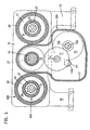
- Fig. 13 . 14 show the sixth drive group 600 of the ejector unit 24.
- Fig. 13 are arranged around a balancing cylinder 112 around two hydraulic piston-cylinder units which act on the ejector unit 24, which may also be designed as a core pull.
- electromechanical spindle drives can be used either instead of the hydraulic piston-cylinder units or, for example, the surface of the compensating cylinder 112 at the same time used as a primary element of a linear motor, in a graphically not shown manner, a sleeve connected to the ejector 24 may be the secondary element.
- the ejector unit 24 is designed as an independent structural unit, as shown in WO-A 97/12741 is known, the disclosure of which is hereby expressly made the subject of the present application.
- the drive is a hollow shaft motor, which receives in itself the actuating element, which can be used by appropriate rotation transmission elements this ejector unit as unscrewing or as core pull.
- any other ejector can be used, provided that it is ensured that a connection to the movable mold carrier 13 is possible.
- Fig. 15 shows the use of an electromechanical drive unit as a first assembly 100 and a hydraulic unit as a drive group 200.
- the structure corresponds to the structure in the earlier patent application 197 50 057.9 ,
- the locking mechanism C drives the drive rod 94 via a belt drive 81.
- the drive rod 94 terminates at the spindle head 95 which is connected via planet 96 with a threaded tube 89 in connection.
- the threaded tube 89 is closed at the end by a closure element 97, so that here again gives the impression of a piston-cylinder unit, since the threaded elements are externally invisible.
- the movable mold carrier is divided in two into the parts 13 ', 13 "in order to be able to receive the belt drive 81.
- the first drive group 100 brings the injection mold M into positive engagement This can be done at any time during the movement by the switching chamber 98 is pressurized, so that the further support member 85, which here is a piston, the bearing sleeve 83 in Fig. 15 presses to the left.
- the movable mold carrier 13 ', 13 "up to any gap between the mold halves or until moved to positive engagement, which adjusts to each other at the latest when planting the two halves of the mold force and thus deformation, depending on the balance of forces between the switching chamber 98 and the pressure chamber 99 to an earlier or later reduction of the distance a to the system of pressure tube 93rd on the spindle head 95 leads. This system prevents further rotation.
- the pressure tube 93 is connected to the further support element 85 designed as a piston.
- the position of the pressure tube can be influenced by the pressure in the switching chamber 98.
Landscapes
- Engineering & Computer Science (AREA)
- Manufacturing & Machinery (AREA)
- Mechanical Engineering (AREA)
- Injection Moulding Of Plastics Or The Like (AREA)
- Moulds For Moulding Plastics Or The Like (AREA)
Abstract
Description
Die Erfindung betrifft eine Spritzgießmaschine zur Verarbeitung von Kunststoffen und anderer plastifizierbarer Massen wie keramische oder pulvrige Massen mit einem mehrere Antriebsgruppen umfassenden modularen Aufbau nach dem Oberbegriff des Anspruches 1.The invention relates to an injection molding machine for processing plastics and other plasticizable materials such as ceramic or powdery masses with a modular structure comprising a plurality of drive groups according to the preamble of claim 1.
Ein derartiger modularer Aufbau ist zwar in seiner Gesamtheit aus dem Stand der Technik nicht bekannt, jedoch ist es aus der
Ausgehend von diesem Stand der Technik liegt der vorliegenden Erfindung die Aufgabe zugrunde, bei einer Spritzgießmaschine der eingangs genannten Gattung die baulichen Voraussetzungen für eine erhöhte Modularität zu schaffen unter Einsatz weitestgehend identischer Bauteile.Based on this prior art, the present invention seeks to provide in an injection molding machine of the type mentioned the structural requirements for increased modularity using largely identical components.
Diese Aufgabe wird durch eine Spritzgießmaschine mit den Merkmalen des Anspruches 1 gelöst.This object is achieved by an injection molding machine with the features of claim 1.
Durch konstruktiven Mehraufwand werden bereits im Vorfeld Anschlußmöglichkeiten an den Teilen der Spritzgießmaschine geschaffen, so daß die verbleibenden Teile der Spritzgießmaschine bereits den unterschiedlichen Anforderungen der verschiedenen Antriebsarten, sei es hydraulisch, pneumatisch, elektromechanisch, als Linearmotor oder elektromagnetisch genügen. Wird dieser Mehraufwand bei der Konstruktion getrieben, erleichtert dies später die Fertigung und verringert den Mehraufwand bei jeder Maschine, da ohne größere Probleme den Wünschen der einzelnen Kunden nachgekommen werden kann. Je mehr Schnittstellen insofern für verschiedene Antriebsarten vorgesehen sind, desto schneller ist die Maschine lieferbar. Ferner schafft diese Modularität Möglichkeiten für den Kunden selbst, die Spritzgießmaschine je nach Spritzteil zu optimieren. So kann es z.B. beim Zweifarbspritzen oder bei großem Durchsatz von Vorteil sein, die Spritzgießeinheit elektrisch zu betreiben, während es bei kleinem Durchsatz aufgrund der Geschwindigkeit von Vorteil sein kann, die Spritzgießeinheit hydraulisch zu betreiben. Aufgrund der gegebenen Modularität kann die hierfür erforderliche Anpassung der Kunde sogar selbst vornehmen.By additional design effort connecting possibilities to the parts of the injection molding machine are created in advance, so that the remaining parts of the injection molding machine already meet the different requirements of the various types of drives, be it hydraulic, pneumatic, electromechanical, linear motor or electromagnetic. If this extra effort is driven in the construction, this facilitates the later production and reduces the overhead of each machine, since without major problems, the wishes of individual customers can be met. The more interfaces are provided for different drive types, the faster the machine is available. Furthermore, this modularity creates opportunities for the customer himself to optimize the injection molding machine depending on the molded part. So it can be e.g. In two-color spraying or at high throughput, it may be advantageous to operate the injection-molding unit electrically, while at a low throughput it may be advantageous, due to the speed, to operate the injection-molding unit hydraulically. Due to the given modularity, the customer can even make the necessary adjustment.
Z.B. kann ein Rotationsübertragungselement in der Einspritzbrücke vorgesehen werden, das sowohl dafür vorgesehen ist, daß rückseitig ein Rotationsmotor angeschlossen wird oder an einer anderen Stelle ein Antriebsrad festgelegt werden kann, so daß über ein Getriebe dieses Element ansteuerbar ist. Für sämtliche Antriebe ist dabei ausreichend Raum an der Spritzgießmaschine zur Verfügung gestellt.For example, a rotation transmission element can be provided in the injection bridge, which is provided both for the fact that a rotary motor is connected at the back or at another point a drive wheel can be set, so that via a transmission of this element can be controlled. For all drives while sufficient space is provided on the injection molding machine.
In der Einspritzbrücke können bauliche Elemente vorgesehen werden, die je nach Antriebsart sogar passiv sind und überhaupt nicht benötigt werden, andererseits aber die Möglichkeit schaffen; problemlos die Antriebsart umzustellen. Hierbei kann der für die verschiedenen Antriebsarten erforderliche Raum dadurch erhalten werden, daß sich auf engstem Raum diese für die verschiedenen Antriebsarten erforderlichen Bauteile kombinieren lassen.In the injection bridge structural elements can be provided, which are even passive depending on the type of drive and are not needed at all, but on the other hand create the opportunity; easy to change the drive. In this case, the space required for the various drive types can be obtained by allowing these components, which are required for the various types of drive, to be combined in the smallest possible space.
Formschließseitig kann der bewegliche Formträger so ausgebildet sein; daß an dieselben Bauteile sowohl elektromechanische Antriebe als auch hydraulische oder pneumatische Antriebe anschließbar sind. Dabei ist nicht zu unterschätzen, daß das Bauteil insofern für die unterschiedlichen Anforderungen vorbereitet sein muß, wobei für die Hydraulik die Dichtheit ebenso gewährleistet sein muß wie für den elektromechanischen Antrieb die Krafteinleitung.Form closing side, the movable mold carrier may be formed so; that both electromechanical drives and hydraulic or pneumatic drives can be connected to the same components. It should not be underestimated that the component must be prepared so far for the different requirements, which must be ensured for the hydraulic tightness as well as for the electromechanical drive, the introduction of force.
Weitere Vorteile ergeben sich aus den Unteransprüchen.Further advantages emerge from the subclaims.
- Fig. 1Fig. 1
- Eine dreidimensionale Ansicht der Spritzgießeinheit mit Blick auf die Einspritzbrükke, wobei sämtliche Antriebsgruppen hydraulisch betrieben sind,A three-dimensional view of the injection molding unit with a view of the Einspritzbrükke, wherein all drive groups are hydraulically operated,
- Fig. 2Fig. 2
-
einen Schnitt durch die Spritzgießeinheit gemäß
Fig. 1 ,a section through the injection molding according toFig. 1 . - Fig. 3Fig. 3
-
einen Schnitt gemäß
Fig. 2 , wobei der Dosierantrieb über ein Hochmomentmotor elektrisch erfolgt,a section according toFig. 2 wherein the dosing drive is electrically powered by a high torque motor, - Fig. 4Fig. 4
-
einen Schnitt gemäß
Fig. 2 , wobei das Fördermittel über ein Getriebe mit Servomotor gedreht wird,a section according toFig. 2 wherein the conveyor is rotated via a gearbox with servomotor, - Fig. 5Fig. 5
-
einen Schnitt nach Linie 5-5 von
Fig. 4 ,a section along line 5-5 ofFig. 4 . - Fig. 6Fig. 6
-
einen Schnitt durch die Spritzgießeinheit im Bereich des Getriebes nach Linie 6-6 von
Fig. 5 ,a section through the injection molding unit in the range of the transmission according to line 6-6 ofFig. 5 . - Fig. 7Fig. 7
- eine dreidimensionale Ansicht von Einspritzbrücke und Getriebe,a three-dimensional view of injection bridge and gear,
- Fig. 8Fig. 8
-
einen Schnitt gemäß
Fig. 2 mit einer veränderten Einspritzbrücke und hydraulischem Einspritzen,a section according toFig. 2 with a modified injection bridge and hydraulic injection, - Fig. 9Fig. 9
-
einen Schnitt gemäß
Fig. 8 mit einer elektromechanischen Einspritzeinheit,a section according toFig. 8 with an electromechanical injection unit, - Fig. 10Fig. 10
-
einen Schnitt gemäß
Fig. 8 , wobei der Düsenfahrantrieb ein Linearmotor ist,a section according toFig. 8 wherein the jet traction drive is a linear motor, - Fig. 11Fig. 11
- eine teilweise geschnittene Seitenansicht eines am Trägerblock befestigten Plastifizierzylinders mit einem hydraulischen Antrieb für eine Verschlußdüse,a partially sectioned side view of a fixed to the support block plasticizing with a hydraulic drive for a closure nozzle,
- Fig. 12Fig. 12
-
eine Darstellung gemäß
Fig. 11 mit einem elektromechanischen Antrieb für die Verschlußdüse,a representation according toFig. 11 with an electromechanical drive for the closure nozzle, - Fig. 13Fig. 13
- eine teilweise geschnittene Seitenansicht einer hydraulisch betriebenen Formschließeinheit,a partially sectioned side view of a hydraulically operated mold clamping unit,
- Fig. 14Fig. 14
-
eine Darstellung gemäß
Fig. 13 , wobei alle Antriebe elektromechanisch erfolgen,a representation according toFig. 13 where all drives are electromechanical, - Fig. 15Fig. 15
- eine Seitenansicht einer Formschließeinheit mit elektromechanischem Schließmechanismus und hydraulischer Aufbringung der Schließkraft,a side view of a mold clamping unit with electromechanical closing mechanism and hydraulic application of the closing force,
- Fig. 16Fig. 16
- eine isometrische Darstellung der Spritzgießmaschine mit den Arbeitsgruppen.an isometric view of the injection molding machine with the working groups.
Die Spritzgießmaschine dient z.B. als Kunststoff-Spritzgießmaschine der Verarbeitung plastifizierbarer Massen wie z.B. von Kunststoffen, pulvrigen oder keramischen Massen. Die Spritzgießmaschine besitzt gemäß
Die Formschließeinheit F besitzt einen stationären Formträger 34 und einen beweglichen Formträger 13. Zwischen den beiden Formträgern bildet sich ein Formspannraum R aus, in dem Formteile eines Spritzgießwerkzeugs M oder einer Spritzgießform am stationären Formträger 34 und am beweglichen Formträger 13 aufgenommen sind. Die Formschließeinheit besitzt einen Schließmechanismus C, der zugleich die erste Antriebsgruppe 100 zum Bewegen des beweglichen Formträgers auf den stationären Formträger 34 zu und von diesem weg darstellt. Zur Abstützung des Schließmechanismus C ist ein erstes Abstützelement 25 vorgesehen, wobei bei "seriellem Schließen" auch ein weiteres Abstützelement vorgesehen sein kann. Bei diesem seriellen Schließen wird über die erste Antriebsgruppe 100 der bewegliche Formträger bis zum Formschluß überführt, während durch eine gesonderte Antriebsgruppe die Schließkraft aufgebracht wird. Als Einrichtung zur Aufbringung der Schließkraft dient die zweite Antriebsgruppe 200, die insbesondere eingesetzt wird, wenn die erste Antriebsgruppe 100 den beweglichen Formträger 13 bis zum Formschluß der Spritzgießform M überführt hat. Bedarfsweise kann jedoch die erste Antriebsgruppe 100 mit der zweiten Antriebsgruppe 200 kombiniert durch ein und dieselbe Antriebsgruppe gebildet sein, was z.B. insbesondere bei einer hydraulischen Lösung möglich ist.The mold clamping unit F has a stationary mold carrier 34 and a
Um Kräfte, die im wesentlichen beim Aufbringen der Schließkraft entstehen, vom ersten Abstützelement 25 auf den stationären Formträger 34 zu übertragen, sind Kraftübertragungsmittel vorgesehen. Diese Kraftübertragungsmittel sind die Holme 86, die zugleich dem Schließmechanismus C und dem beweglichen Formträger 13 als Führung dienen. Als Kraftübertragungselement können auch andere Elemente vorgesehen sein, wie z.B. sogenannte "C-Bügel", die die beim Schließen und beim Spritzgießen auftretenden Kräfte um den Formspannraum R herum vom stationären Formträger 34 zum beweglichen Formträger 13 leiten, wie dies dem Fachmann bekannt ist.In order to transmit forces, which arise essentially when applying the closing force, from the
Die Spritzgießeinheit S besitzt gemäß
Die Spritzgießeinheit S umfaßt ferner eine Einspritzbrücke 14 sowie einen Dosierantrieb 41,41',41" für das Fördermittel 12 und die Plastifiziereinheit P als dritte Antriebsgruppe 300, die mit der Einspritzbrücke 14 verbindbar ist. Der Dosierantrieb dient insbesondere zum Rotieren des Fördermittels, da dieses Fördermittel meist eine Förderschnecke ist. Wird hier ein Förderkolben vorgesehen, fällt die dritte Antriebsgruppe 300 mit den Einspritzmittein 43 der fünften Antriebsgruppe 500 zusammen.The injection molding unit S further comprises an
Als Einspritzmittel ist wenigstens ein zur Spritzachse s-s parallelachsiger Antrieb - meist zur Erzielung einer symmetrischen Krafteinleitung jedoch mehrere Antriebe - vorgesehen, der als fünfte Antriebsgruppe 500 zur Relativbewegung des Fördermittels 12 gegenüber dem Plastifizierzylinder 11 dient. Durch diese Axialbewegung des Fördermittels wird das vor der Förderschnecke befindliche plastifizierte Material in den Formhohlraum des Spritzgießwerkzeugs M eingespritzt.As injection means, at least one to the injection axis s-s parallel axis drive - usually to achieve a symmetrical force but several drives - provided, which serves as a
Um ferner die Spritzgießeinheit S vom stationären Formträger 34 abheben zu können bzw. an diesen anlegen zu können, wird als vierte Antriebsgruppe 400 wenigstens ein zur Spritzachse s-s parallelachsiger Düsenfahrantrieb 42 vorgesehen. Auch hier können mehrere Antriebe wie im Ausführungsbeispiel vorgesehen werden.In order furthermore to be able to lift the injection molding unit S from the stationary mold carrier 34 or to be able to apply it to the latter, the
Ist das in den Formhohlraum eingespritzte plastifizierte Material erhärtet, wird es als Formling über eine Auswerfereinheit 24 ausgeworfen, die an beliebiger Stelle innerhalb der Spritzgießmaschine, jedoch meist in der Spritzachse s-s formschließseitig angeordnet ist. Die Auswerfereinheit 24 kann jedoch auch als Kernzug ausgebildet sein. Der Antrieb von Auswerfereinheit 24 bzw. Kernzug erfolgt über eine sechste Antriebsgruppe 600.If the plasticized material injected into the mold cavity has hardened, it is ejected as a molded article via an
Schließlich ist eine siebte Antriebsgruppe 700 vorgesehen, über die eine Düsennadel 51 über ein Gestänge 50 ansteuerbar ist, um die Düsenmündung 52a im Falle einer Verschlußdüse bedarfsweise zu verschließen.Finally, a
Über die Spritzgießmaschine verteilt können Multifunktionselemente angeordnet sein. Wenigstens eine der Antriebsgruppen 100,200,300,400,500,600,700 ist mit der Spritzgießmaschine über wenigstens eines dieser Multifunktionselemente verbunden. Das Multifunktionselement dient insofern als Schnittstelle für den Anschluß verschiedener Antriebsarten. Es ermöglicht wahlweise den Anschluß von wenigstens zwei verschiedenen Antriebsarten wie z.B. elektromechanische Antriebe, hydraulische Antriebe, pneumatische Antriebe, Linearmotor-Antriebe oder elektromagnetische Antriebe. Durch den Einsatz dieser Multifunktionselemente wird erreicht, daß die verbleibende Spritzgießmaschine so weit als möglich unverändert bleibt. Dadurch kann die Modularität vervollkommnet werden, so daß auf die Wünsche einzelner Kunden schneller eingegangen werden kann. Gleichzeitig kann der Kunde selbst je nach Einsatzzweck kurzfristig Antriebsarten austauschen und an die jeweiligen Anforderungen anpassen. Dazu wird für die Antriebsgruppen 100,200,300,400,500,600,700 unabhängig vom jeweiligen Antrieb ausreichend Raum an der Spritzgießmaschine zur Unterbringung jeder Antriebsart zur Verfügung gestellt. Ferner sind die Multifunktionselemente so dimensioniert, daß sie auch den unterschiedlichen Belastungen, die die einzelnen Antriebsarten mit sich bringen, gerecht werden.Distributed over the injection molding machine can be arranged multifunction elements. At least one of the
Dies wird im folgenden an verschiedenen Beispielen näher erläutert.This will be explained in more detail below with reference to various examples.
Die Einspritzbrücke 14' trägt mittig ein Rotationsübertragungselement 46, das gemeinsam mit der Einspritzbrücke 14' als Multifunktionselement für die dritte Antriebsgruppe 300 ausgebildet ist. Das Rotationsübertragungselement 46 dient zur Übertragung der Rotation eines Dosierantriebs 41, der zur Aufbereitung des zu verarbeitenden Materials dient und hierzu das als Förderschnecke ausgebildete Fördermittel dreht Das Rotationsübertragungselement 46 befindet sich in einer Ausnehmung 14a' der Einspritzbrücke 14' und ist dort über Lager 15 drehbar gelagert und in axialer Richtung zudem festgelegt.The injection bridge 14 'carries centrally a
Das Rotationsübertragungselement 46 besitzt hier rückseitig eine Ausnehmung 46a, in das der Antriebsschaft 41a des Dosierantriebs 41 zur Wirkverbindung eingreift. Der Dosierantrieb ist in
Während in
Der Aufbau von Getriebe und Dosiermotor 41' der dritten Antriebsgruppe 300 ergibt sich aus den
Eine weitere Ausführungsform des Dosierantriebs und vor allem der Einspritzmittel 43 zeigen die
In
Wie in der älteren Patentanmeldung erläutert, sind das erste Antriebselement 19 und das weitere Antriebselement 20 koaxial zueinander angeordnet. Werden gemäß
Die
Die gewünschte Modularität läßt sich auch auf der Formschließseite bei der Formschließeinheit F verwirklichen. Gemäß
In
Zusammengefaßt können damit folgende unterschiedliche Antriebssysteme an einer Spritzgießmaschine vorgesehen werden, wobei diese Auflistung keinen Anspruch auf Vollständigkeit erhebt.
- 1. Seite der Spritzgießeinheit
- a) Dosieren (Rotation)
- hydraulisch mit Ölmotor (radial, axial, Zahnrad, Drehmoment)
- elektrisch mit konstantem Motor oder Regetmotor und Getriebe
- b) Einspritzen (Translation)
- hydraulisch mit Zylinder
- elektrisch mit Umsetzung Rotation in Translation
- pneumatisch mit Zylinder
- elektrisch mit Linearmotor
- c) Düse fahren (Translation)
- hydraulisch mit Zylinder
- elektrisch mit Umsetzung Rotation in Translation
- pneumatisch mit Zylinder
- elektrisch mit Linearmotor
- d) Düse verschließen (Translation)
- hydraulisch mit Zylinder
- pneumatisch mit Zylinder
- Elektromagnet
- Elektromotor Rotation in Translation
- elektrisch über Linearmotor
- a) Dosieren (Rotation)
- 2. Formschließseite
- a) Werkzeug fahren (Translation)
- hydraulisch mit Zylinder über Kniehebel oder unmittelbar
- elektrisch mit Umsetzung Rotation in Translation
- Linearmotor
- b) Schließkraft mit Hochdruck (Translation)
- hydraulisch mit Zylinder über Kniehebel oder unmittelbar
- elektrisch mit Kniehebel oder Exzenter
- c) Auswerfer (Translation)
- hydraulisch mit Zylinder
- pneumatisch mit Zylinder
- elektrisch mit Umsetzung Rotation in Translation
- elektrischer Linearmotor
- a) Werkzeug fahren (Translation)
- 3. Allgemein
- a) Kernzüge wie Ausstoßer
- b) Schutztür wie Ausstoßer
- 1st side of the injection molding unit
- a) dosing (rotation)
- hydraulic with oil motor (radial, axial, gear, torque)
- electrically with constant motor or Regetmotor and transmission
- b) injection (translation)
- hydraulically with cylinder
- electrically with conversion rotation in translation
- pneumatic with cylinder
- electrically with linear motor
- c) drive nozzle (translation)
- hydraulically with cylinder
- electrically with conversion rotation in translation
- pneumatic with cylinder
- electrically with linear motor
- d) Close the nozzle (Translation)
- hydraulically with cylinder
- pneumatic with cylinder
- electromagnet
- Electric motor rotation in translation
- electrically via linear motor
- a) dosing (rotation)
- 2. Mold closing side
- a) driving tools (translation)
- hydraulically with cylinder via toggle lever or directly
- electrically with conversion rotation in translation
- linear motor
- b) closing force with high pressure (translation)
- hydraulically with cylinder via toggle lever or directly
- electric with toggle or eccentric
- c) ejector (translation)
- hydraulically with cylinder
- pneumatic with cylinder
- electrically with conversion rotation in translation
- electric linear motor
- a) driving tools (translation)
- 3. General
- a) core trains like ejectors
- b) Protective door as ejector
- 1010
- Trägerblockcarrier block
- 1111
- Plastifizierzylinderplasticizing
- 1212
- Fördermittelfunding
- 13,13',1313,13 ', 13
- " beweglicher Formträger"movable mold carrier
- 13a13a
- Ausnehmungrecess
- 13b13b
- Anlageflächecontact surface
- 14,14'14.14 '
- EinspritzbrückeInjection bridge
- 14a14a
- Anlagefläche'Contact surface '
- 14a'14a '
- Ausnehmungrecess
- 1515
- Lagerelement für 46Bearing element for 46
- 1616
- elektromechanischer Antriebelectromechanical drive
- 16a16a
- LinearbewegungsmittelLinear displacement means
- 16b16b
- Gewinderohrthreaded pipe
- 16c16c
- Spindelkopfspindle head
- 16d16d
- Planetenplanet
- 1717
- Lagerelement für 16aBearing element for 16a
- 1818
- Abstützungsupport
- 18a18a
- topfartige Ausnehmungcup-shaped recess
- 1919
- erstes Antriebselement von 500first drive element of 500
- 2020
- weiteres Antriebselement von 41further drive element of 41
- 21,4021.40
- Axial-LagerelementThrust bearing element
- 2222
- Gehäusedeckelhousing cover
- 2424
- Auswerfereinheitejector
- 2525
- erstes Abstützelementfirst support element
- 2626
- DruckübertragungselementPressure transmission element
- 2727
- Zylindercylinder
- 28,2928.29
- Zylinderkammercylinder chamber
- 3030
- Ringkolbenannular piston
- 3131
- HolmHolm
- 32,3332.33
- Zylinderdeckelcylinder cover
- 3434
- stationärer Formträgerstationary mold carrier
- 8383
- Lagerhülsebearing sleeve
- 8484
- WälzgewindeantriebWälzgewindeantrieb
- 8585
- weiteres Abstützelementanother support element
- 8686
- FührungsholmHandlebar
- 8787
- Hydraulikblockhydraulic block
- 8888
- Lagerelementbearing element
- 8989
-
Gewinderohr (
Fig. 14 )Threaded tube (Fig. 14 ) - 9090
-
Kolben (
Fig. 13 )Piston (Fig. 13 ) - 9191
- Ventilkolbenplunger
- 9292
- Begrenzungselementlimiting element
- 9393
- Druckrohrpressure pipe
- 9494
- Antriebsstangedrive rod
- 9595
- Spindelkopfspindle head
- 9696
- Planetenplanet
- 9797
- Verschlußelementclosure element
- 9898
- Schaltkammerswitching chamber
- 9999
- Druckkammerpressure chamber
- 100100
- erste Antriebsgruppefirst drive group
- 110110
- Zylindercylinder
- 111111
- Kolbenstangepiston rod
- 112112
- Ausgleichszylindercompensating cylinder
- 3535
- Maschinenfußmachine base
- 3636
- Bohrungdrilling
- 41,41',4141,41 ', 41
- " Dosierantrieb"Metering drive
- 41a,41a'41a, 41a '
- Antriebswelledrive shaft
- 4242
- DüsenfahrantriebJet propulsion
- 4343
- EinspritzmittelInjection means
- 4545
- Verriegelungsmechanismuslocking mechanism
- 4646
- RotationsübertragungselementRotation transmitting member
- 46a46a
- Ausnehmungrecess
- 46b46b
- Abschnittsection
- 4747
- Getriebegehäusegearbox
- 4848
-
Zylinderraum (
Fig. 8 )Cylinder space (Fig. 8 ) - 4949
- Kolbenpiston
- 50,50'50.50 '
- Gestänge für 51Linkage for 51
- 50a50a
- Anschlußpunktconnection point
- 5151
- Düsennadelnozzle needle
- 5252
- Düsenkörpernozzle body
- 52a52a
- Düsenmündungnozzle orifice
- 5353
- Verbindungsmuffecoupling sleeve
- 5454
- Düseneinsatznozzle insert
- 5555
- Schwenkhebelpivoting lever
- 6060
- Zylindercylinder
- 61,6261.62
- Zylinderkammercylinder chamber
- 63,6463.64
- Zylinderdeckelcylinder cover
- 70,71,7270,71,72
- Ritzelpinion
- 71a,72a71a, 72a
- Achseaxis
- 72b72b
- Ritzelpinion
- 7575
- Sekundärelementsecondary element
- 8080
- Gehäusewandunghousing
- 8181
- Riementriebbelt drive
- 8282
- Kolben-Zylinder-EinheitPiston-cylinder unit
- 200-700200-700
- zweite bis siebte Antriebsgruppesecond to seventh drive group
- aa
- Abstanddistance
- a-aa-a
- Wirkachseeffective axis
- s-ss-s
- Spritzachseinjection axis
- CC
- Schließmechanismusclosing mechanism
- FF
- FormschließeinheitMold closing unit
- MM
- Spritzgießwerkzeuginjection mold
- PP
- Plastifiziereinheitplasticizing
- RR
- FormspannraumMold clamping area
- SS
- Spritzgießeinheitinjection molding
- MFMF
- MultifunktionselementMultifunctional element
Claims (19)
- Injection moulding machine for processing plastics materials and other plasticisable materials, having a modular structure comprising a plurality of driving groups, said machine having- a machine base (35),- a mould closing unit (F) having- a stationary mould carrier (34) connected to the machine base (35),- a movable mould carrier (13), which provides a mould clamping chamber (R) between itself and the stationary mould carrier (34),- at least one injection moulding tool (M), the moulding parts of which can be accommodated in the mould clamping chamber (R) on the stationary mould carrier (34) and on the movable mould carrier (13),- a closing mechanism (C) as a first driving group (100) for moving the movable mould carrier (13) towards the stationary mould carrier (34) and away from said stationary mould carrier so as to close the injection moulding tool (M),- force transmitting means for transmitting substantially the closing force from the closing mechanism (C) to the stationary mould carrier (34),- and an injection moulding unit (S), havingcharacterised in that at least one of the driving groups (100, 300, 400, 500) is connectable to the injection moulding machine via at least one multifunctional element, which serves via two different types of interfaces selectively for the connection of at least two different drive types selected from the group of electromechanical drives, hydraulic drives, pneumatic drives, linear motors or electromagnetic drives as the driving group with an otherwise unchanged injection moulding machine, whereby space is made available for the driving groups (100, 300, 400, 500), independently of the particular drive, on the injection moulding machine for accommodating each type of drive.- a plasticising unit (P), which comprises a plasticising cylinder (11) and a feeding means (12), which is accommodated in the plasticising cylinder, as well as a nozzle mouth (52a) on the end face, which mouth lies in an injection axis (s-s),- a carrier block (10), which is disposed on the machine base (35) so as to be displaceable along the injection axis (s-s), and on which block the plasticising unit (P) is detachably mounted,- an injection bridge (14),- a metering drive (41,41') for the feeding means (12) of the plasticising unit (P) as a third driving group (300), which is connectable to the injection bridge (14),- at least one nozzle moving drive (42), which is axis-parallel to the injection axis (s-s), as a fourth driving group (400) for moving the nozzle mouth (52a) towards the injection moulding tool (M) and away from said tool, and- at least one injecting means (43), which is axis-parallel to the injection axis (s-s), as a fifth driving group (500) for the movement of the feeding means (12) relative to the plasticising cylinder (11),
- Injection moulding machine according to claim 1, characterised in that the closing mechanism comprises a first supporting element (25) for support purposes, and in that an arrangement, which is also connectable to the injection moulding machine via a multifunctional element, for applying the closing force is provided as the second driving group (200), as soon as the first driving group (100) has transferred the movable mould carrier to achieve the closure of the injection mould (M).
- Injection moulding machine according to claim 1 or 2, characterised in that an ejector unit (24) is provided as the sixth driving group (600), which is also connectable to one of the mould carriers (11,12) via a multifunctional element.
- Injection moulding machine according to claim 3, characterised in that even the ejector (24), as a core puller, can communicate with the multifunctional element, which communicates with the ejector unit (24).
- Injection moulding machine according to one of claims 1 to 4, characterised in that a drive for the nozzle needle (51) of a closable nozzle body (52) is provided as the seventh driving group (700), which drive is also connectable to the injection moulding machine via a multifunctional element.
- Injection moulding machine according to one of the preceding claims, characterised in that, on the side of the injection moulding unit, the injection bridge (14') and a rotation transmitting element (46), which is rotatably mounted therein, for transmitting the rotation of a metering drive (41,41') for the third driving group (300) are configured as multifunctional elements.
- Injection moulding machine according to claim 6, characterised in that the rotation transmitting element (46) has a recess (46a), in which the drive shaft (41 a) of the metering drive (41) engages for the operative connection, the metering drive (41) being an hydraulic rotary motor or an electrically operated high-torque motor.
- Injection moulding machine according to claim 6 or 7, characterised in that the rotation transmitting element (46) protrudes from the injection bridge (14') with a portion (46b), to which a transmission housing (47), with an associated transmission, is connectable, which transmission is driven by a metering drive (41').
- Injection moulding machine according to one of claims 1 to 5, characterised in that the injection bridge (14) has an abutment face (14a) as the multifunctional element for the fifth driving group (500), which face serves as an abutment for a pressure transmitting element, which is configured as injecting means (43) and is supported on a support (18), which communicates with the injection bridge (14), said pressure transmitting element preferably being hydraulically or electromechanically displaceable as injecting means (43).
- Injection moulding machine according to claim 9, characterised in that the support (18) has a cup-like recess (18a), which either forms a cylinder chamber (48) for the injecting means (43), which is configured as piston (49), or accommodates a non-rotatable part of an electromechanical spindle drive, which co-operates with a rotatable part mounted on the injection bridge (14).
- Injection moulding machine according to claim 9 or 10, characterised in that there is non-rotatably accommodated in a cup-like recess (18a) of the support (18) a threaded tube (16b) which co-operates with a spindle head (16c), the spindle head (16c) being disposed on the end of a linear moving means (16a), which centrally penetrates the pressure transmitting element, configured as tube (26), and which is rotatable via a first driving element (19) disposed in the injection bridge (14).
- Injection moulding machine according to one of the preceding claims, characterised in that a driving element (20), which is coaxial with a first driving element (19) for the injecting means (43), is disposed in the injection bridge (14) for the rotation of the feeding means.
- Injection moulding machine according to claim 11 or 12, characterised in that there is provided between first driving element (19) and additional driving element (20) an axial bearing element (21) which, on the one hand, serves as the force transmitting element and, on the other hand, serves as the separating means between the driving elements (19,20).
- Injection moulding machine according to one of the preceding claims, characterised in that the cylinder covers (32,33), which are disposed on the guide bars (31) configured as the force transmitting means, are configured as the multifunctional element for the fourth driving group (400), which covers accommodate therebetween the cylinder (27), which is configured either as the cylinder for an hydraulic annular piston (30) or as the wall for a secondary element (75) of a linear motor.
- Injection moulding machine according to one of the preceding claims, characterised in that a cylinder (27) of the fourth driving group (400) is configured on the outside as the multifunctional element for the fifth driving group (500) and serves as a guide for the injection bridge (14,14').
- Injection moulding machine according to claim 15, characterised in that the cylinder (27) is the piston rod for an hydraulic injecting means (43).
- Injection moulding machine according to claim 5, characterised in that a housing wall (80) is mounted on the carrier block (10) as the multifunctional element for the attachment of the seventh driving group (700) for actuating the nozzle needle (51), which wall is either penetrated by the rod assembly (50) for actuating the nozzle needle (51) when an hydraulic actuation is effected, or is operatively connected to another rod assembly (50') via a rolling thread drive (84), the housing wall (80) serving as the housing for said drive.
- Injection moulding machine according to one of the preceding claims, characterised in that the movable mould carrier (13) has, as the multifunctional element for the first and second driving groups (100,200), a recess (13a) which either has a base supporting a threaded tube (89) of an electromechanical drive or accommodates a part of an hydraulic piston (90), the cylinder (110) of said piston being secured on the edge of the recess (13a).
- Injection moulding machine according to one of claims 2 to 17, characterised in that there is disposed between first supporting element (25) and movable mould carrier (13;13',13") an additional supporting element (85) as the multifunctional element, which is actuatable via a switching chamber (98) actuatable with hydraulic medium, the switching chamber (98) permitting the movement of the first driving group (100) when it is under pressure, while the switching chamber (98) blocks the movement of the first driving group (100) when the switching chamber (98) is free of pressure, the pressure of the hydraulic medium in the switching chamber (98) being connectable in exactly the same way as the second driving group (200).
Applications Claiming Priority (3)
| Application Number | Priority Date | Filing Date | Title |
|---|---|---|---|
| DE19847298 | 1998-10-14 | ||
| DE19847298A DE19847298C2 (en) | 1998-10-14 | 1998-10-14 | Injection molding machine with a modular structure comprising several drive groups |
| PCT/EP1999/007582 WO2000021729A1 (en) | 1998-10-14 | 1999-10-09 | Injection molding machine having a modular construction which comprises a plurality of drive groups |
Publications (3)
| Publication Number | Publication Date |
|---|---|
| EP1121237A1 EP1121237A1 (en) | 2001-08-08 |
| EP1121237B1 EP1121237B1 (en) | 2002-12-11 |
| EP1121237B2 true EP1121237B2 (en) | 2010-08-04 |
Family
ID=7884405
Family Applications (1)
| Application Number | Title | Priority Date | Filing Date |
|---|---|---|---|
| EP99952546A Expired - Lifetime EP1121237B2 (en) | 1998-10-14 | 1999-10-09 | Injection molding machine having a modular construction which comprises a plurality of drive groups |
Country Status (7)
| Country | Link |
|---|---|
| US (1) | US6517337B1 (en) |
| EP (1) | EP1121237B2 (en) |
| JP (1) | JP2002527256A (en) |
| AT (1) | ATE229422T1 (en) |
| CA (1) | CA2347458C (en) |
| DE (2) | DE19847298C2 (en) |
| WO (1) | WO2000021729A1 (en) |
Families Citing this family (23)
| Publication number | Priority date | Publication date | Assignee | Title |
|---|---|---|---|---|
| DE10022192A1 (en) * | 2000-05-03 | 2001-11-15 | Mannesmann Ag | Device for removing injection molded parts |
| DE50201729D1 (en) * | 2001-02-15 | 2005-01-13 | Mannesmann Plastics Machinery | LOCKING DEVICE IN AN INJECTION MOLDING MACHINE FOR PLASTICS |
| AT5362U1 (en) | 2001-05-11 | 2002-06-25 | Engel Gmbh Maschbau | DEVICE FOR INJECTION MOLDING PLASTIC |
| CN100457419C (en) | 2002-10-31 | 2009-02-04 | 住友重机械工业株式会社 | Molding machine and control method thereof |
| DE10309906B3 (en) | 2003-02-25 | 2004-06-09 | Karl Hehl | Mold closing mechanism, at an injection molding machine, is on a support at the machine foot with an angular adjustment, to give an accurate alignment of the mold carriers |
| DE102004033690A1 (en) * | 2004-07-09 | 2006-02-16 | Demag Ergotech Gmbh | Injection molding machine |
| DE102004057164A1 (en) * | 2004-11-26 | 2006-06-01 | Krauss-Maffei Kunststofftechnik Gmbh | injection molding machine |
| DE202005021060U1 (en) * | 2005-09-14 | 2007-01-18 | Siemens Ag | Injection molding machine, especially for injection stamping, comprises an injection unit with a linear drive unit, a closure unit with a linear drive unit, and a preplastication unit |
| USD559285S1 (en) * | 2005-10-03 | 2008-01-08 | Galomb David E | Injection molding machine |
| US7772266B2 (en) | 2006-02-15 | 2010-08-10 | Dendreon Corporation | Small-molecule modulators of TRP-P8 activity |
| US20070296121A1 (en) * | 2006-06-07 | 2007-12-27 | Husky Injection Molding Systems Ltd. | Molding-system drive |
| US20070296281A1 (en) * | 2006-06-07 | 2007-12-27 | Husky Injection Molding Systems Ltd. | Electrical motor |
| US7695266B2 (en) * | 2006-11-02 | 2010-04-13 | Husky Injection Molding Systems Ltd. | Molding structure |
| DE102007042643A1 (en) | 2007-09-07 | 2009-04-02 | Siemens Ag | Method for operating an injection device for an injection molding machine, injection device and injection molding machine with such an injection device |
| GB2478732B (en) | 2010-03-15 | 2014-08-20 | Kraft Foods R & D Inc | Improvements in injection moulding |
| CN102211383B (en) * | 2010-04-01 | 2013-11-06 | 永高股份有限公司 | Secondary slide block core pulling mechanism for plastic mould |
| DE102010046275A1 (en) * | 2010-09-22 | 2012-03-22 | Netstal-Maschinen Ag | Universal auxiliary control for an injection molding machine |
| JP5980865B2 (en) * | 2014-09-11 | 2016-08-31 | ファナック株式会社 | Injection molding machine |
| DE102016205554B4 (en) * | 2016-04-04 | 2022-02-24 | Rekers Gmbh Maschinen- Und Anlagenbau | Mandrel device for a block molding machine, block molding machine and method for producing shaped blocks |
| JP6867978B2 (en) * | 2018-06-13 | 2021-05-12 | 日精樹脂工業株式会社 | Injection molding machine and its molding method |
| JP7605574B2 (en) * | 2021-06-14 | 2024-12-24 | 株式会社日本製鋼所 | Injection unit and injection molding machine |
| DE102024131208A1 (en) | 2024-10-25 | 2026-04-30 | Arburg Gmbh + Co Kg | Modular plastics processing machine |
| DE102024131207B3 (en) * | 2024-10-25 | 2025-11-27 | Arburg Gmbh + Co Kg | Injection molding unit for processing plastics, injection molding machine equipped with it and associated kit |
Citations (1)
| Publication number | Priority date | Publication date | Assignee | Title |
|---|---|---|---|---|
| DE2247386A1 (en) † | 1972-09-27 | 1974-03-28 | Demag Ag | Injection moulding machine rotary drive for screw - with hydraulic forward drive, having shaft coupling permitting use of different types of motor |
Family Cites Families (5)
| Publication number | Priority date | Publication date | Assignee | Title |
|---|---|---|---|---|
| EP0576925B1 (en) * | 1992-06-23 | 1997-08-20 | Battenfeld Kunststoffmaschinen Ges.m.b.H. | Injection unit for injection moulding machines |
| DE19536565C2 (en) | 1995-10-02 | 1998-07-16 | Karl Hehl | Injection molding machine for processing plasticizable materials |
| DE19536567C2 (en) | 1995-10-02 | 1998-12-17 | Karl Hehl | Mold clamping unit with a device for the treatment and / or removal of molded parts |
| DE19731833C1 (en) * | 1997-07-24 | 1999-01-14 | Karl Hehl | Injection molding unit for an injection molding machine |
| DE19750057C2 (en) | 1997-11-12 | 2000-08-03 | Karl Hehl | Mold clamping unit for an injection molding machine |
-
1998
- 1998-10-14 DE DE19847298A patent/DE19847298C2/en not_active Expired - Fee Related
-
1999
- 1999-10-09 WO PCT/EP1999/007582 patent/WO2000021729A1/en not_active Ceased
- 1999-10-09 DE DE59903783T patent/DE59903783D1/en not_active Expired - Lifetime
- 1999-10-09 JP JP2000575673A patent/JP2002527256A/en active Pending
- 1999-10-09 AT AT99952546T patent/ATE229422T1/en active
- 1999-10-09 EP EP99952546A patent/EP1121237B2/en not_active Expired - Lifetime
- 1999-10-09 CA CA002347458A patent/CA2347458C/en not_active Expired - Fee Related
- 1999-10-09 US US09/807,395 patent/US6517337B1/en not_active Expired - Lifetime
Patent Citations (1)
| Publication number | Priority date | Publication date | Assignee | Title |
|---|---|---|---|---|
| DE2247386A1 (en) † | 1972-09-27 | 1974-03-28 | Demag Ag | Injection moulding machine rotary drive for screw - with hydraulic forward drive, having shaft coupling permitting use of different types of motor |
Also Published As
| Publication number | Publication date |
|---|---|
| EP1121237A1 (en) | 2001-08-08 |
| EP1121237B1 (en) | 2002-12-11 |
| DE59903783D1 (en) | 2003-01-23 |
| DE19847298C2 (en) | 2000-11-02 |
| CA2347458A1 (en) | 2000-04-20 |
| JP2002527256A (en) | 2002-08-27 |
| US6517337B1 (en) | 2003-02-11 |
| CA2347458C (en) | 2008-11-25 |
| WO2000021729A1 (en) | 2000-04-20 |
| DE19847298A1 (en) | 2000-04-27 |
| ATE229422T1 (en) | 2002-12-15 |
Similar Documents
| Publication | Publication Date | Title |
|---|---|---|
| EP1121237B2 (en) | Injection molding machine having a modular construction which comprises a plurality of drive groups | |
| DE19920626C2 (en) | Injection molding machine for processing plastics | |
| DE2113414A1 (en) | Closing, locking and preloading device for casting molds | |
| EP1097035B1 (en) | Injection molding unit for an injection molding machine | |
| DE29619781U1 (en) | Blow molding machine | |
| EP0508277A2 (en) | Drive apparatus for the displacement and/or the positioning force for injection moulding machines | |
| EP1339537B1 (en) | Injection unit for an injection moulding machine | |
| EP1768828B1 (en) | Injection moulding machine | |
| EP3710222B1 (en) | Mold-closing unit for an injection molding machine, and method for locking a force transmission element | |
| EP0576837B1 (en) | Injection mouding machine with stack mould | |
| DE102021130687B3 (en) | Multi-component injection molding machine | |
| DE102009052816A1 (en) | Device for closing and opening press of blow molding machine, has hydraulic drive unit arranged with piston and cylinder in axial direction while moving spindle, where distances of electrical drive and hydraulic drive are added | |
| EP3959058B1 (en) | Injection molding unit for an injection molding machine for processing plastics | |
| EP0107778B1 (en) | Method and apparatus for the treatment of plastifiable material | |
| EP1802441B1 (en) | Closing unit for an injection moulding machine comprising a stack mould | |
| EP0585671B1 (en) | Ejection unit for injection moulding machines | |
| DE102017223822A1 (en) | Mold-closing unit for an injection molding machine and method for locking a power transmission element | |
| EP4458547A1 (en) | Mould closing unit and method for operating a mould closing unit of a machine for processing plastics | |
| DE19605747C2 (en) | Drive unit for plasticizing and injection units of plastic injection molding machines | |
| EP0639444B1 (en) | Injection unit | |
| DE19536567A1 (en) | Mold clamping unit with a device for the treatment and / or removal of molded parts | |
| EP1848577B1 (en) | Injection moulding machine for processing plastic materials | |
| DE19514346C1 (en) | Lubrication system integrating economically with injection moulding machine | |
| DE19535081A1 (en) | Two-platen injection moulding machine with positioning drive and guides below mould assembly area | |
| EP2719517B1 (en) | Injection moulding machine |
Legal Events
| Date | Code | Title | Description |
|---|---|---|---|
| PUAI | Public reference made under article 153(3) epc to a published international application that has entered the european phase |
Free format text: ORIGINAL CODE: 0009012 |
|
| 17P | Request for examination filed |
Effective date: 20010320 |
|
| AK | Designated contracting states |
Kind code of ref document: A1 Designated state(s): AT BE CH CY DE DK ES FI FR GB GR IE IT LI LU MC NL PT SE |
|
| GRAG | Despatch of communication of intention to grant |
Free format text: ORIGINAL CODE: EPIDOS AGRA |
|
| 17Q | First examination report despatched |
Effective date: 20020102 |
|
| GRAG | Despatch of communication of intention to grant |
Free format text: ORIGINAL CODE: EPIDOS AGRA |
|
| GRAH | Despatch of communication of intention to grant a patent |
Free format text: ORIGINAL CODE: EPIDOS IGRA |
|
| GRAH | Despatch of communication of intention to grant a patent |
Free format text: ORIGINAL CODE: EPIDOS IGRA |
|
| GRAA | (expected) grant |
Free format text: ORIGINAL CODE: 0009210 |
|
| AK | Designated contracting states |
Kind code of ref document: B1 Designated state(s): AT CH DE FR GB IT LI |
|
| REF | Corresponds to: |
Ref document number: 229422 Country of ref document: AT Date of ref document: 20021215 Kind code of ref document: T |
|
| REG | Reference to a national code |
Ref country code: GB Ref legal event code: FG4D Free format text: NOT ENGLISH |
|
| REG | Reference to a national code |
Ref country code: CH Ref legal event code: EP |
|
| REG | Reference to a national code |
Ref country code: CH Ref legal event code: NV Representative=s name: LUCHS & PARTNER PATENTANWAELTE |
|
| REF | Corresponds to: |
Ref document number: 59903783 Country of ref document: DE Date of ref document: 20030123 |
|
| GBT | Gb: translation of ep patent filed (gb section 77(6)(a)/1977) |
Effective date: 20030307 |
|
| ET | Fr: translation filed | ||
| PLBQ | Unpublished change to opponent data |
Free format text: ORIGINAL CODE: EPIDOS OPPO |
|
| PLBI | Opposition filed |
Free format text: ORIGINAL CODE: 0009260 |
|
| 26 | Opposition filed |
Opponent name: ENGEL AUSTRIA GMBH Effective date: 20030905 |
|
| PLAX | Notice of opposition and request to file observation + time limit sent |
Free format text: ORIGINAL CODE: EPIDOSNOBS2 |
|
| PLAX | Notice of opposition and request to file observation + time limit sent |
Free format text: ORIGINAL CODE: EPIDOSNOBS2 |
|
| PLAX | Notice of opposition and request to file observation + time limit sent |
Free format text: ORIGINAL CODE: EPIDOSNOBS2 |
|
| PLBB | Reply of patent proprietor to notice(s) of opposition received |
Free format text: ORIGINAL CODE: EPIDOSNOBS3 |
|
| PLAY | Examination report in opposition despatched + time limit |
Free format text: ORIGINAL CODE: EPIDOSNORE2 |
|
| PLBC | Reply to examination report in opposition received |
Free format text: ORIGINAL CODE: EPIDOSNORE3 |
|
| PGFP | Annual fee paid to national office [announced via postgrant information from national office to epo] |
Ref country code: GB Payment date: 20061024 Year of fee payment: 8 |
|
| PLAB | Opposition data, opponent's data or that of the opponent's representative modified |
Free format text: ORIGINAL CODE: 0009299OPPO |
|
| R26 | Opposition filed (corrected) |
Opponent name: ENGEL AUSTRIA GMBH Effective date: 20030905 |
|
| APBP | Date of receipt of notice of appeal recorded |
Free format text: ORIGINAL CODE: EPIDOSNNOA2O |
|
| APAH | Appeal reference modified |
Free format text: ORIGINAL CODE: EPIDOSCREFNO |
|
| APBQ | Date of receipt of statement of grounds of appeal recorded |
Free format text: ORIGINAL CODE: EPIDOSNNOA3O |
|
| GBPC | Gb: european patent ceased through non-payment of renewal fee |
Effective date: 20071009 |
|
| PG25 | Lapsed in a contracting state [announced via postgrant information from national office to epo] |
Ref country code: GB Free format text: LAPSE BECAUSE OF NON-PAYMENT OF DUE FEES Effective date: 20071009 |
|
| APBU | Appeal procedure closed |
Free format text: ORIGINAL CODE: EPIDOSNNOA9O |
|
| PUAH | Patent maintained in amended form |
Free format text: ORIGINAL CODE: 0009272 |
|
| STAA | Information on the status of an ep patent application or granted ep patent |
Free format text: STATUS: PATENT MAINTAINED AS AMENDED |
|
| 27A | Patent maintained in amended form |
Effective date: 20100804 |
|
| AK | Designated contracting states |
Kind code of ref document: B2 Designated state(s): AT CH DE FR GB IT LI |
|
| REG | Reference to a national code |
Ref country code: CH Ref legal event code: AEN Free format text: AUFRECHTERHALTUNG DES PATENTES IN GEAENDERTER FORM |
|
| PGFP | Annual fee paid to national office [announced via postgrant information from national office to epo] |
Ref country code: FR Payment date: 20111103 Year of fee payment: 13 |
|
| REG | Reference to a national code |
Ref country code: FR Ref legal event code: ST Effective date: 20130628 |
|
| PG25 | Lapsed in a contracting state [announced via postgrant information from national office to epo] |
Ref country code: FR Free format text: LAPSE BECAUSE OF NON-PAYMENT OF DUE FEES Effective date: 20121031 |
|
| PGFP | Annual fee paid to national office [announced via postgrant information from national office to epo] |
Ref country code: IT Payment date: 20131030 Year of fee payment: 15 |
|
| REG | Reference to a national code |
Ref country code: DE Ref legal event code: R082 Ref document number: 59903783 Country of ref document: DE Representative=s name: PATENTANWAELTE REINHARDT & POHLMANN PARTNERSCH, DE |
|
| REG | Reference to a national code |
Ref country code: DE Ref legal event code: R082 Ref document number: 59903783 Country of ref document: DE Representative=s name: RPK PATENTANWAELTE REINHARDT, POHLMANN UND KAU, DE Effective date: 20140731 Ref country code: DE Ref legal event code: R082 Ref document number: 59903783 Country of ref document: DE Representative=s name: PATENTANWAELTE REINHARDT & POHLMANN PARTNERSCH, DE Effective date: 20140731 Ref country code: DE Ref legal event code: R081 Ref document number: 59903783 Country of ref document: DE Owner name: KEINATH, RENATE, DE Free format text: FORMER OWNER: HEHL, KARL, 72290 LOSSBURG, VERSTORBEN, DE Effective date: 20140731 |
|
| PG25 | Lapsed in a contracting state [announced via postgrant information from national office to epo] |
Ref country code: IT Free format text: LAPSE BECAUSE OF NON-PAYMENT OF DUE FEES Effective date: 20141009 |
|
| PGFP | Annual fee paid to national office [announced via postgrant information from national office to epo] |
Ref country code: CH Payment date: 20151026 Year of fee payment: 17 |
|
| PGFP | Annual fee paid to national office [announced via postgrant information from national office to epo] |
Ref country code: DE Payment date: 20160805 Year of fee payment: 18 |
|
| PGFP | Annual fee paid to national office [announced via postgrant information from national office to epo] |
Ref country code: AT Payment date: 20161024 Year of fee payment: 18 |
|
| REG | Reference to a national code |
Ref country code: CH Ref legal event code: PL |
|
| PG25 | Lapsed in a contracting state [announced via postgrant information from national office to epo] |
Ref country code: CH Free format text: LAPSE BECAUSE OF NON-PAYMENT OF DUE FEES Effective date: 20161031 Ref country code: LI Free format text: LAPSE BECAUSE OF NON-PAYMENT OF DUE FEES Effective date: 20161031 |
|
| REG | Reference to a national code |
Ref country code: DE Ref legal event code: R119 Ref document number: 59903783 Country of ref document: DE |
|
| REG | Reference to a national code |
Ref country code: AT Ref legal event code: MM01 Ref document number: 229422 Country of ref document: AT Kind code of ref document: T Effective date: 20171009 |
|
| PG25 | Lapsed in a contracting state [announced via postgrant information from national office to epo] |
Ref country code: DE Free format text: LAPSE BECAUSE OF NON-PAYMENT OF DUE FEES Effective date: 20180501 |
|
| PG25 | Lapsed in a contracting state [announced via postgrant information from national office to epo] |
Ref country code: AT Free format text: LAPSE BECAUSE OF NON-PAYMENT OF DUE FEES Effective date: 20171009 |