EP1121237B1 - Injection molding machine having a modular construction which comprises a plurality of drive groups - Google Patents
Injection molding machine having a modular construction which comprises a plurality of drive groups Download PDFInfo
- Publication number
- EP1121237B1 EP1121237B1 EP99952546A EP99952546A EP1121237B1 EP 1121237 B1 EP1121237 B1 EP 1121237B1 EP 99952546 A EP99952546 A EP 99952546A EP 99952546 A EP99952546 A EP 99952546A EP 1121237 B1 EP1121237 B1 EP 1121237B1
- Authority
- EP
- European Patent Office
- Prior art keywords
- drive
- injection moulding
- injection
- moulding machine
- cylinder
- Prior art date
- Legal status (The legal status is an assumption and is not a legal conclusion. Google has not performed a legal analysis and makes no representation as to the accuracy of the status listed.)
- Expired - Lifetime
Links
- 238000001746 injection moulding Methods 0.000 title claims abstract description 72
- 238000010276 construction Methods 0.000 title description 2
- 238000002347 injection Methods 0.000 claims description 61
- 239000007924 injection Substances 0.000 claims description 61
- 230000005540 biological transmission Effects 0.000 claims description 26
- 230000007246 mechanism Effects 0.000 claims description 14
- 239000000463 material Substances 0.000 claims description 5
- 239000004033 plastic Substances 0.000 claims description 4
- 229920003023 plastic Polymers 0.000 claims description 4
- 239000000969 carrier Substances 0.000 claims description 3
- 238000012545 processing Methods 0.000 claims description 3
- 238000000465 moulding Methods 0.000 claims description 2
- 238000005096 rolling process Methods 0.000 claims 1
- 238000013519 translation Methods 0.000 description 22
- 239000007921 spray Substances 0.000 description 6
- 239000000919 ceramic Substances 0.000 description 2
- 239000000243 solution Substances 0.000 description 2
- 241000196324 Embryophyta Species 0.000 description 1
- 235000003332 Ilex aquifolium Nutrition 0.000 description 1
- 241000209027 Ilex aquifolium Species 0.000 description 1
- 230000004308 accommodation Effects 0.000 description 1
- 230000009286 beneficial effect Effects 0.000 description 1
- 238000005266 casting Methods 0.000 description 1
- 230000008859 change Effects 0.000 description 1
- 239000003795 chemical substances by application Substances 0.000 description 1
- 230000008878 coupling Effects 0.000 description 1
- 238000010168 coupling process Methods 0.000 description 1
- 238000005859 coupling reaction Methods 0.000 description 1
- 238000006073 displacement reaction Methods 0.000 description 1
- 238000005553 drilling Methods 0.000 description 1
- 238000003780 insertion Methods 0.000 description 1
- 230000037431 insertion Effects 0.000 description 1
- 238000005461 lubrication Methods 0.000 description 1
- 238000004519 manufacturing process Methods 0.000 description 1
- 238000000034 method Methods 0.000 description 1
- 238000003825 pressing Methods 0.000 description 1
- 230000008569 process Effects 0.000 description 1
- 230000002035 prolonged effect Effects 0.000 description 1
- 230000001681 protective effect Effects 0.000 description 1
- 230000001105 regulatory effect Effects 0.000 description 1
- 238000005507 spraying Methods 0.000 description 1
- 238000012546 transfer Methods 0.000 description 1
Images


Classifications
-
- B—PERFORMING OPERATIONS; TRANSPORTING
- B29—WORKING OF PLASTICS; WORKING OF SUBSTANCES IN A PLASTIC STATE IN GENERAL
- B29C—SHAPING OR JOINING OF PLASTICS; SHAPING OF MATERIAL IN A PLASTIC STATE, NOT OTHERWISE PROVIDED FOR; AFTER-TREATMENT OF THE SHAPED PRODUCTS, e.g. REPAIRING
- B29C45/00—Injection moulding, i.e. forcing the required volume of moulding material through a nozzle into a closed mould; Apparatus therefor
- B29C45/17—Component parts, details or accessories; Auxiliary operations
- B29C45/46—Means for plasticising or homogenising the moulding material or forcing it into the mould
- B29C45/47—Means for plasticising or homogenising the moulding material or forcing it into the mould using screws
- B29C45/50—Axially movable screw
- B29C45/5008—Drive means therefor
-
- B—PERFORMING OPERATIONS; TRANSPORTING
- B29—WORKING OF PLASTICS; WORKING OF SUBSTANCES IN A PLASTIC STATE IN GENERAL
- B29C—SHAPING OR JOINING OF PLASTICS; SHAPING OF MATERIAL IN A PLASTIC STATE, NOT OTHERWISE PROVIDED FOR; AFTER-TREATMENT OF THE SHAPED PRODUCTS, e.g. REPAIRING
- B29C45/00—Injection moulding, i.e. forcing the required volume of moulding material through a nozzle into a closed mould; Apparatus therefor
- B29C45/03—Injection moulding apparatus
- B29C45/07—Injection moulding apparatus using movable injection units
-
- B—PERFORMING OPERATIONS; TRANSPORTING
- B29—WORKING OF PLASTICS; WORKING OF SUBSTANCES IN A PLASTIC STATE IN GENERAL
- B29C—SHAPING OR JOINING OF PLASTICS; SHAPING OF MATERIAL IN A PLASTIC STATE, NOT OTHERWISE PROVIDED FOR; AFTER-TREATMENT OF THE SHAPED PRODUCTS, e.g. REPAIRING
- B29C45/00—Injection moulding, i.e. forcing the required volume of moulding material through a nozzle into a closed mould; Apparatus therefor
- B29C45/17—Component parts, details or accessories; Auxiliary operations
- B29C45/20—Injection nozzles
- B29C45/23—Feed stopping equipment
- B29C45/231—Needle valve systems therefor
-
- B—PERFORMING OPERATIONS; TRANSPORTING
- B29—WORKING OF PLASTICS; WORKING OF SUBSTANCES IN A PLASTIC STATE IN GENERAL
- B29C—SHAPING OR JOINING OF PLASTICS; SHAPING OF MATERIAL IN A PLASTIC STATE, NOT OTHERWISE PROVIDED FOR; AFTER-TREATMENT OF THE SHAPED PRODUCTS, e.g. REPAIRING
- B29C45/00—Injection moulding, i.e. forcing the required volume of moulding material through a nozzle into a closed mould; Apparatus therefor
- B29C45/17—Component parts, details or accessories; Auxiliary operations
- B29C45/40—Removing or ejecting moulded articles
- B29C45/4005—Ejector constructions; Ejector operating mechanisms
-
- B—PERFORMING OPERATIONS; TRANSPORTING
- B29—WORKING OF PLASTICS; WORKING OF SUBSTANCES IN A PLASTIC STATE IN GENERAL
- B29C—SHAPING OR JOINING OF PLASTICS; SHAPING OF MATERIAL IN A PLASTIC STATE, NOT OTHERWISE PROVIDED FOR; AFTER-TREATMENT OF THE SHAPED PRODUCTS, e.g. REPAIRING
- B29C45/00—Injection moulding, i.e. forcing the required volume of moulding material through a nozzle into a closed mould; Apparatus therefor
- B29C45/17—Component parts, details or accessories; Auxiliary operations
- B29C45/64—Mould opening, closing or clamping devices
- B29C45/68—Mould opening, closing or clamping devices hydro-mechanical
Definitions
- the invention relates to an injection molding machine for processing plastics and others plastifiable masses such as ceramic or powdery masses with one of several drive groups comprehensive modular structure according to the preamble of claim 1.
- Such a modular structure is in its entirety from the prior art not known, but it is known from EP 0 576 925 A1, for example, within individual Drive groups of an injection molding machine both on the side of the injection molding unit and also to provide liquid-cooled electric servomotors on the form-locking side.
- motors of this type can be used in any way on an injection molding machine, however, it is necessary to use the respective connection elements on the injection molding machine to be replaced if other types of drives are used.
- Extensive parts must therefore be kept in stock in order to meet To build customers' machines accordingly. This leads to prolonged Delivery times.
- the present invention is based on the object the structural requirements for an injection molding machine of the type mentioned at the beginning to create an increased modularity using largely identical Components.
- a rotation transmission element may be provided in the injection bridge, the It is both intended that a rotary motor is connected to the rear or to elsewhere a drive wheel can be set so that this via a gear Element is controllable. There is sufficient space for all drives Injection molding machine provided.
- Structural elements can be provided in the injection bridge, depending on the type of drive are even passive and are not needed at all, but on the other hand the possibility create; easily change the drive type.
- the for the different Required types of drive can be obtained by being in a confined space have these components combined for the different drive types combined.
- the movable mold carrier can be designed in this way on the mold-closing side; that to the same Components both electromechanical drives and hydraulic or pneumatic drives can be connected. It should not be underestimated that the component in this respect for the different requirements must be prepared, the tightness for the hydraulics the force transmission must be ensured as well as for the electromechanical drive.
- the injection molding machine is used e.g. as a plastic injection molding machine processing plasticizable Masses such as of plastics, powdery or ceramic masses.
- the 16 has a modular structure with several drive groups, which are partly assigned to the mold clamping unit F and partly to the injection molding unit S. Mold clamping unit F and injection molding unit are arranged on the machine base 35.
- the mold clamping unit F has a stationary mold carrier 34 and a movable one Mold carrier 13.
- a mold clamping space R is formed between the two mold carriers, in the molded parts of an injection mold M or an injection mold on the stationary Mold carrier 34 and on the movable mold carrier 13 are added.
- the mold clamping unit has a locking mechanism C, which at the same time the first drive group 100 Moving the movable mold carrier to and from the stationary mold carrier 34 represents away.
- a first support element is provided to support the locking mechanism C. 25 provided, with "serial closing" also provided a further support element can be. During this serial closing, the Movable mold carriers transferred to form closure, while by a separate drive group the closing force is applied.
- the second drive group 200 which is used in particular when the first Drive group 100 the movable mold carrier 13 until the mold of the injection mold M convicted. If necessary, however, the first drive group 100 can be combined with the second Drive group 200 combined can be formed by one and the same drive group what e.g. is possible in particular with a hydraulic solution.
- Power transmission means intended. These power transmission means are the spars 86, which at the same time Closing mechanism C and the movable mold carrier 13 serve as a guide.
- Power transmission element can also be provided, such as e.g. so-called "C-bracket", which around the forces occurring during closing and injection molding Mold clamping space R around from the stationary mold carrier 34 to the movable mold carrier 13 conduct as is known to those skilled in the art.
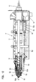
- the injection molding unit S has a plasticizing unit P, which has a plasticizing cylinder 11 and a conveying means 12 received in the plasticizing cylinder. face side the injection molding unit ends with a nozzle body 52 which has a nozzle orifice 52a, which lies in a spray axis s-s (Fig. 11, 12).
- the plasticizing unit P is on one the carrier base 10 movably arranged along the spray axis s-s releasably attached.
- the injection molding unit S further comprises an injection bridge 14 and a metering drive 41, 41 ', 41 "for the conveying means 12 and the plasticizing unit P as the third drive group 300, which can be connected to the injection bridge 14.
- the metering drive is used in particular for rotating of the funding, since this funding is usually a screw conveyor. Will be here Provided delivery pistons, the third drive group 300 falls with the injection center 43 of the fifth drive group 500 together.
- the injection means is at least one drive parallel to the spray axis s-s - mostly for Achieving a symmetrical introduction of force, however, several drives - provided that as a fifth drive group 500 for the relative movement of the conveying means 12 with respect to the Plasticizing cylinder 11 is used.
- This axial movement of the conveyor means that before Conveyor screw located plasticized material in the mold cavity of the injection mold M injected.
- the fourth drive group 400 s-s parallel-axis nozzle travel drive 42 is provided.
- the plasticized material injected into the mold cavity When the plasticized material injected into the mold cavity has hardened, it becomes a molding ejected via an ejector unit 24, which is located anywhere in the injection molding machine, however, it is usually arranged in the injection axis s-s on the form-locking side.
- the Ejector unit 24 can, however, also be designed as a core pull.
- the drive from the ejector unit 24 or core pull is carried out via a sixth drive group 600.
- a seventh drive group 700 is provided, via which a nozzle needle 51 can be controlled via a linkage 50 around the nozzle mouth 52a in the case of a closure nozzle to close if necessary.
- Multifunctional elements can be arranged distributed over the injection molding machine. At least one of the drive groups 100,200,300,400,500,600,700 is with the injection molding machine connected via at least one of these multifunction elements.
- the multifunctional element serves as an interface for connecting different types of drives. It enables the connection of at least two different drive types such as e.g. electromechanical drives, hydraulic drives, pneumatic drives, linear motor drives or electromagnetic drives.
- electromechanical drives e.g. electromechanical drives, hydraulic drives, pneumatic drives, linear motor drives or electromagnetic drives.
- 100,200,300,400,500,600,700 is used for the drive groups Sufficient space on the injection molding machine for accommodation regardless of the respective drive made available to every drive type. Furthermore, the multifunction elements dimensioned so that they also withstand the different loads that the individual drive types bring along, do justice.
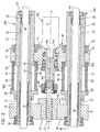
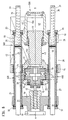
- Fig. 1 shows a purely hydraulic injection molding unit.
- This injection molding unit is partially enlarged shown in section in Fig. 2.
- the fifth drive group 500 serves as an injection means an injection cylinder 60 with cylinder space 61 and 62.
- This injection cylinder is closed by cylinder covers 63 and 64, which on the cylinder 27 of a nozzle driving unit the fourth drive group 400 slide.
- Hydraulic medium or pneumatic becomes the injection bridge 14 'along the spray axis s-s moves, with this movement, the conveyor 12 in the plasticizing cylinder 11 moves axially becomes.
- the plasticizing cylinder 11 is detachably attached to the support block 10, on which the Cylinder 27 is fixed.
- the cylinder 27 is coaxially penetrated by spars 31, which at the same time carry the piston 30 for the fourth drive group 400 of the jet travel drives.
- spars 31 which at the same time carry the piston 30 for the fourth drive group 400 of the jet travel drives.
- the injection bridge 14 ' carries in the middle a rotation transmission element 46, which together formed with the injection bridge 14 'as a multifunction element for the third drive group 300 is.
- the rotation transmission element 46 serves to transmit the rotation of a Metering drive 41, which is used to process the material to be processed and for this purpose the conveyor designed as a screw conveyor rotates the rotation transmission element 46 is located in a recess 14a 'of the injection bridge 14' and is there via the bearing 15 rotatably mounted and also fixed in the axial direction.
- the rotation transmission element 46 here has a recess 46a on the back, into which the drive shaft 41a of the metering drive 41 engages for operative connection.
- the dosing drive is a hydraulic rotary motor in Fig. 2, instead an electrically operated one High torque motor as in Fig. 3 are used. In this respect, both engines attack the same recess 46a, which can be clearly seen in FIG. 1.
- the structure of the transmission and metering motor 41 'of the third drive group 300 results from 5 to 7.
- the pinion 72 is mounted with the axis 72a in the gear housing and has a smaller pinion 72b on the same axis, which meshes with the pinion 71.
- the pinion 71 is mounted in the gear housing 47 with its axis 71a.
- the Pinion 71 meshes with pinion 70, which according to FIG. 5 with the rotation transmission element 46 is connected.
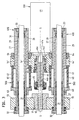
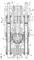
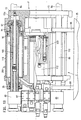
- FIG. 8 Another embodiment of the metering drive and above all the injection means 43 show Figures 8 to 10.
- the injection bridge 14 as a multifunction element for the fifth Assembly 500 is provided and has a contact surface 14a.
- This contact surface can 8 a pressure transmission element designed as an injection means 43 as a system serve.
- the pressure transmission element is supported on a support 18.
- Fig. 8 is the support 18 at one end of the cylinder 27 while the support block is arranged at the other end of the cylinder 27, so that over the cylinder 27th forms a force frame over which the injection means 43 is supported.
- a hydraulic or pneumatic piston 49 is provided as the injection means 43.
- This piston is guided in a pot-like recess 18a of the support 18.
- An electric motor is used as the metering drive 41 ' provided that drives the further drive element 20 via a gearbox, the Bearing 15 is mounted in the injection bridge.
- a first drive element is located in the injection bridge 14 19 provided, which is in the function here. It can be seen that the cylinder 27 serves only the injection bridge 14 and the support 18 as a guide, without further Cylinder, as interposed in Figs. 1 to 7.
- Fig. 9 differs from Fig. 8 in that the injection means 43 is an electromechanical Drive 16 is provided, as it is from the older German patent application 197 31st 833.9 is known.
- the pot-like recess 18a of the support 18 supports part of the electromechanical spindle drive. The one interacting with this non-rotatable part rotatable part of this drive is mounted on the injection bridge 14.
- In the pot-like A threaded tube 16b comes to lie in the recess, which cooperates with a spindle head 16c, the spindle head 16c being arranged at the end of a linear movement means 16a is.
- This linear movement means 16a penetrates the pressure tube 26 Pressure transmission element coaxial and is driven by the first drive element 19, wherein the drive takes place via an electric motor of the fifth drive group 500.
- the pressure pipe 26, the is fixed in the recess 14a of the injection bridge, dips into the threaded tube in any position 16b, so that there is the impression of a piston-cylinder unit. This helps to protect the drive unit from dirt and enables insertion permanent lubrication.
- Threaded tube 16b and spindle head are connected to each other via planet 16d in connection.
- Pressure tube 26 and threaded tube 16b are indirect via an axial bearing element 40 connected.
- the forces occurring during injection are not via the linear movement means 16a to the drive element 19, but from the threaded tube 16b are transmitted to the spindle head 16c via the planets 16d.
- the spindle head passes these forces on the thrust bearing element 40, so that the pressure pipe to Pressure transmission element is.
- Via injection bridge 14, bearing element 17 and first drive element 19 the power flow continues via the axial bearing element 21 to the other Drive element 20 and the conveying means 12. Therefore, the linear movement means 16a only have to be dimensioned to the rotational forces and no longer to the pressure transmission.
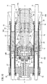
- Fig. 10 differs from Fig. 9 in that the cylinder 27 is the primary element of a Linear motor is.
- a secondary element is arranged on the Hotm 31 as the nozzle travel drive 42.
- a relative movement takes place by appropriately loading the primary element of the primary element to the secondary element and thus the nozzle movement.
- Fig. 2,9 and 10 makes it clear that for different types of drive if the cylinder covers 32, 33 remain the same, only the cylinder is replaced accordingly must become. Is the different volumes of the hydraulic spaces 61, 62 in FIG. 2 waived and the cylinder would be prepared for this, possibly as the primary element of a linear motor To be used is basically no longer an exchange of the cylinder 27 required.
- the cylinder 27 serves as the cylinder cover 32, 33 as Multifunctional element for the fourth assembly 400, which is either inside as a cylinder for a hydraulic ring piston 30 or as a wall for the secondary element 75 of the linear motor serves.
- the cylinder can be used as a multifunction element for the fifth Module 500 be designed and serves the injection bridge 14, 14 'as a guide or optionally the piston rod of a hydraulic injection means 43.
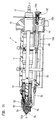
- FIGS 11, 12 show different embodiments of a plasticizing unit with a closure nozzle.
- the plasticizing unit P has a plasticizing cylinder 11 in which the conveying means 12 is included.
- the plasticizing unit is detachably attached to the carrier block 10, wherein when detaching the drive mechanism for the closure nozzle on the plasticizing cylinder remains.
- the nozzle needle 51 via a linkage 50 and a pivot lever 55 controlled.
- the nozzle body 52 is connected to the plasticizing cylinder via a connecting sleeve 53 11 connected.
- a nozzle insert 54 is arranged in the nozzle body 52.
- the linkage 50 ends in one Connection point 50a, with which it can be fixed to a hydraulic piston-cylinder unit is.
- a housing wall 80 is provided, which is connected to the plasticizing cylinder 11 is changed.
- the rod 50 penetrates this housing wall 80.
- this housing wall is e.g. used as the housing of a hollow shaft motor, the The linkage 50 'is actuated electromechanically via a roller screw drive 84.
- the linkage 50 ' is replaced by linkage 50.
- a comparison of the two representations shows that all elements for connecting the hollow shaft motor or another electrical Motors are provided so that only linkage and drive group are replaced must, e.g. to achieve a switch to clean room conditions at the customer.
- the movable mold carrier 13 is a multifunctional element trained for the first and second drive group 100,200.
- the mold clamping unit is supported by bearing elements 88 on the machine base 35.
- the locking mechanism C is connected to the stationary mold carrier 34.
- the Closing mechanism C moves the movable mold carrier 13, which in the exemplary embodiments with a first support element 25 either via a threaded tube 89 or the cylinder 110 connected to an elongated movement unit in the form of a force frame is. Hydraulic drive groups are controlled from a hydraulic block 87. In the fully hydraulic configuration according to FIG. 13, the movable mold carrier 13 has a recess 13a.
- the piston rod 111 is the first Assembled assembly 100 for moving the movable mold carrier 13 until the positive connection.
- the recess 13a is in this case part of a pressure chamber within the cylinder 110.
- the first drive group 100 is also the piston rod 111 of the device for applying the closing force of the second drive group 200. It carries the piston 90, of the overflow channels, which are closed by a valve piston 91, the Movement is limited by a limiting element 92.
- the drive groups are electromechanical. Still, the hydraulic block 87, the further support element 85, the guide bars 86 and above all the movable Maintain mold carrier 13. While in Fig. 13 the cylinder 110 of the second assembly 200 for applying the closing force on the edge of the recess 13a is used in FIG 14 shows the recess 13a with a contact surface 13b with a threaded pipe 89 as a contact. This threaded tube is connected to planet 96, which is driven by a spindle head 95 are. The drive takes place via a drive rod 94 which is in a pressure pipe 93 rotates freely. Externally, there appears to be a piston-cylinder unit even when moving. The closing force can be shown in a manner not shown in the drawing, e.g. by a short-stroke cylinder can be applied, which acts on the further support element 85.
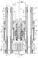
- FIG. 13 show the sixth drive group 600 of the ejector unit 24.
- two hydraulic piston-cylinder units are arranged around a compensating cylinder 112, which act on the ejector unit 24, which can also be designed as a core pull can.
- electromechanical spindle drives or e.g. the surface of the compensating cylinder 112 is also used as the primary element of a linear motor are, one connected to the ejector 24 in a manner not shown in the drawing Sleeve can be the secondary element.
- the ejector unit 24 can also move directly according to FIG. 14 Mold carrier 13 can be arranged.
- the ejector unit 24 is an independent structural one Designed unit, as is known from WO-A 97/12741, the disclosure content hereby expressly to the subject of the present application is made.
- the drive is a hollow shaft motor that contains the actuating element takes up, this ejector unit by appropriate rotation transmission elements can be used as unscrewing device or core pull. Instead of one Any other ejector can also be used, if ensured is that a connection to the movable mold carrier 13 is possible.
- the structure corresponds to that Structure in the earlier patent application 197 50 057.9.
- the locking mechanism C drives via a belt drive 81 to the drive rod 94.
- the drive rod 94 ends at the spindle head 95, which is connected to a threaded tube 89 via planet 96.
- the threaded pipe 89 is closed on the end face by a closure element 97, so that also here the impression of a piston-cylinder unit results, since the threaded elements externally are invisible.
- the movable mold carrier is divided into two parts 13 ', 13 "in order to to be able to take up the belt drive 81.
- the first drive group 100 does that Injection mold M up to positive locking.
- the first drive group 100 comes with its rotatable element 94 while reducing the Distance a in plant. This can happen at any time during the movement by that the switching chamber 98 is pressurized so that the further support element 85, which is a piston here, presses the bearing sleeve 83 to the left in FIG. 15.
- the first drive group 100 becomes the movable mold carrier 13 ', 13 "up to any one Gap between the mold halves or moved to the form fit, at the latest when the two halves of the casting mold are in contact with one another, a force and thus a deformation adjusts as a function of the force ratio between the switching chamber 98 and the pressure chamber 99 to reduce the distance a to earlier or later System of the pressure pipe 93 leads to the spindle head 95.
- This system prevents another Rotation.
- the pressure chamber 99 is activated at any point, so that, regardless of whether a positive connection has already been achieved or not, the switching chamber 98 is actively or passively relieved.
- the pressure pipe 93 is with the other designed as a piston Support element 85 connected. The position of the pressure pipe is due to the pressure in the Switching chamber 98 can be influenced.
- the further structure and operation of this Please refer to the older German patent application mentioned above.
Landscapes
- Engineering & Computer Science (AREA)
- Manufacturing & Machinery (AREA)
- Mechanical Engineering (AREA)
- Injection Moulding Of Plastics Or The Like (AREA)
- Moulds For Moulding Plastics Or The Like (AREA)
Abstract
Description
Die Erfindung betrifft eine Spritzgießmaschine zur Verarbeitung von Kunststoffen und anderer plastifizierbarer Massen wie keramische oder pulvrige Massen mit einem mehrere Antriebsgruppen umfassenden modularen Aufbau nach dem Oberbegriff des Anspruches 1.The invention relates to an injection molding machine for processing plastics and others plastifiable masses such as ceramic or powdery masses with one of several drive groups comprehensive modular structure according to the preamble of claim 1.
Ein derartiger modularer Aufbau ist zwar in seiner Gesamtheit aus dem Stand der Technik nicht bekannt, jedoch ist es aus der EP 0 576 925 A1 zum Beispiel bekannt, innerhalb einzelner Antriebsgruppen einer Spritzgießmaschine sowohl auf der Seite der Spritzgießeinheit als auch formschließseitig flüssigkeitsgekühlte elektrische Servomotoren vorzusehen. Damit können zwar derartige Motoren beliebig an einer Spritzgießmaschine eingesetzt werden, jedoch ist es erforderlich, an der Spritzgießmaschine die jeweiligen Anschlußelemente mit auszutauschen, falls andere Antriebsarten verwendet werden. Insbesondere im Werk des Herstellers müssen deshalb umfangreiche Teile vorgehalten werden, um ganz nach den Wünschen der Kunden Maschinen entsprechend aufzubauen. Dies führt zu verlängerten Lieferzeiten.Such a modular structure is in its entirety from the prior art not known, but it is known from EP 0 576 925 A1, for example, within individual Drive groups of an injection molding machine both on the side of the injection molding unit and also to provide liquid-cooled electric servomotors on the form-locking side. In order to motors of this type can be used in any way on an injection molding machine, however, it is necessary to use the respective connection elements on the injection molding machine to be replaced if other types of drives are used. Especially in the work of Extensive parts must therefore be kept in stock in order to meet To build customers' machines accordingly. This leads to prolonged Delivery times.
Ausgehend von diesem Stand der Technik liegt der vorliegenden Erfindung die Aufgabe zugrunde, bei einer Spritzgießmaschine der eingangs genannten Gattung die baulichen Voraussetzungen für eine erhöhte Modularität zu schaffen unter Einsatz weitestgehend identischer Bauteile. Starting from this prior art, the present invention is based on the object the structural requirements for an injection molding machine of the type mentioned at the beginning to create an increased modularity using largely identical Components.
Diese Aufgabe wird durch eine Spritzgießmaschine mit den Merkmalen des Anspruches 1 gelöst.This object is achieved by an injection molding machine with the features of claim 1 solved.
Durch konstruktiven Mehraufwand werden bereits im Vorfeld Anschlußmöglichkeiten an den Teilen der Spritzgießmaschine geschaffen, so daß die verbleibenden Teile der Spritzgießmaschine bereits den unterschiedlichen Anforderungen der verschiedenen Antriebsarten, sei es hydraulisch, pneumatisch, elektromechanisch, als Linearmotor oder elektromagnetisch genügen. Wird dieser Mehraufwand bei der Konstruktion getrieben, erleichtert dies später die Fertigung und verringert den Mehraufwand bei jeder Maschine, da ohne größere Probleme den Wünschen der einzelnen Kunden nachgekommen werden kann. Je mehr Schnittstellen insofern für verschiedene Antriebsarten vorgesehen sind, desto schneller ist die Maschine lieferbar. Ferner schafft diese Modularität Möglichkeiten für den Kunden selbst, die Spritzgießmaschine je nach Spritzteil zu optimieren. So kann es z.B. beim Zweifarbspritzen oder bei großem Durchsatz von Vorteil sein, die Spritzgießeinheit elektrisch zu betreiben, während es bei kleinem Durchsatz aufgrund der Geschwindigkeit von Vorteil sein kann, die Spritzgießeinheit hydraulisch zu betreiben. Aufgrund der gegebenen Modularität kann die hierfür erforderliche Anpassung der Kunde sogar selbst vornehmen.Due to additional constructive effort, connection options to the Parts of the injection molding machine created so that the remaining parts of the injection molding machine already the different requirements of the different drive types hydraulic, pneumatic, electromechanical, as a linear motor or electromagnetic suffice. If this extra effort is made in the construction, this will make it easier later Manufacturing and reduces the additional effort for each machine, since without major problems the wishes of the individual customers can be met. The more interfaces insofar as different types of drive are provided, the faster the machine available. This modularity also creates opportunities for the customer himself, the injection molding machine to optimize depending on the molded part. For example, with two-color spraying or at high throughput be advantageous to operate the injection molding unit electrically while it can be beneficial at low throughput due to the speed that Operate injection molding unit hydraulically. Due to the given modularity, the the customer can even make the necessary adjustments themselves.
Z.B. kann ein Rotationsübertragungselement in der Einspritzbrücke vorgesehen werden, das sowohl dafür vorgesehen ist, daß rückseitig ein Rotationsmotor angeschlossen wird oder an einer anderen Stelle ein Antriebsrad festgelegt werden kann, so daß über ein Getriebe dieses Element ansteuerbar ist. Für sämtliche Antriebe ist dabei ausreichend Raum an der Spritzgießmaschine zur Verfügung gestellt.For example, a rotation transmission element may be provided in the injection bridge, the It is both intended that a rotary motor is connected to the rear or to elsewhere a drive wheel can be set so that this via a gear Element is controllable. There is sufficient space for all drives Injection molding machine provided.
In der Einspritzbrücke können bauliche Elemente vorgesehen werden, die je nach Antriebsart sogar passiv sind und überhaupt nicht benötigt werden, andererseits aber die Möglichkeit schaffen; problemlos die Antriebsart umzustellen. Hierbei kann der für die verschiedenen Antriebsarten erforderliche Raum dadurch erhalten werden, daß sich auf engstem Raum diese für die verschiedenen Antriebsarten erforderlichen Bauteile kombinieren lassen.Structural elements can be provided in the injection bridge, depending on the type of drive are even passive and are not needed at all, but on the other hand the possibility create; easily change the drive type. Here, the for the different Required types of drive can be obtained by being in a confined space have these components combined for the different drive types combined.
Formschließseitig kann der bewegliche Formträger so ausgebildet sein; daß an dieselben Bauteile sowohl elektromechanische Antriebe als auch hydraulische oder pneumatische Antriebe anschließbar sind. Dabei ist nicht zu unterschätzen, daß das Bauteil insofern für die unterschiedlichen Anforderungen vorbereitet sein muß, wobei für die Hydraulik die Dichtheit ebenso gewährleistet sein muß wie für den elektromechanischen Antrieb die Krafteinleitung. The movable mold carrier can be designed in this way on the mold-closing side; that to the same Components both electromechanical drives and hydraulic or pneumatic drives can be connected. It should not be underestimated that the component in this respect for the different requirements must be prepared, the tightness for the hydraulics the force transmission must be ensured as well as for the electromechanical drive.
Weitere Vorteile ergeben sich aus den Unteransprüchen.Further advantages result from the subclaims.
- Fig. 1Fig. 1
- Eine dreidimensionale Ansicht der Spritzgießeinheit mit Blick auf die Einspritzbrükke, wobei sämtliche Antriebsgruppen hydraulisch betrieben sind,A three-dimensional view of the injection molding unit with a view of the injection bridge, all drive groups are hydraulically operated,
- Fig. 2Fig. 2
- einen Schnitt durch die Spritzgießeinheit gemäß Fig. 1,2 shows a section through the injection molding unit according to FIG. 1,
- Fig. 3Fig. 3
- einen Schnitt gemäß Fig. 2, wobei der Dosierantrieb über ein Hochmomentmotor elektrisch erfolgt,a section according to FIG. 2, wherein the metering drive via a high torque motor done electrically,
- Fig. 4Fig. 4
- einen Schnitt gemäß Fig. 2, wobei das Fördermittel über ein Getriebe mit Servomotor gedreht wird,a section of FIG. 2, wherein the funding via a gear with a servo motor is rotated
- Fig. 5Fig. 5
- einen Schnitt nach Linie 5-5 von Fig. 4,a section along line 5-5 of Fig. 4,
- Fig. 6Fig. 6
- einen Schnitt durch die Spritzgießeinheit im Bereich des Getriebes nach Linie 6-6 von Fig. 5,a section through the injection molding unit in the area of the transmission according to line 6-6 5,
- Fig. 7Fig. 7
- eine dreidimensionale Ansicht von Einspritzbrücke und Getriebe,a three-dimensional view of the injection bridge and gearbox,
- Fig. 8Fig. 8
- einen Schnitt gemäß Fig. 2 mit einer veränderten Einspritzbrücke und hydraulischem Einspritzen,a section of FIG. 2 with a modified injection bridge and hydraulic Injection,
- Fig. 9Fig. 9
- einen Schnitt gemäß Fig. 8 mit einer elektromechanischen Einspritzeinheit,8 shows a section according to FIG. 8 with an electromechanical injection unit,
- Fig. 10Fig. 10
- einen Schnitt gemäß Fig. 8, wobei der Düsenfahrantrieb ein Linearmotor ist,8, wherein the nozzle drive is a linear motor,
- Fig. 11Fig. 11
- eine teilweise geschnittene Seitenansicht eines am Trägerblock befestigten Plastifizierzylinders mit einem hydraulischen Antrieb für eine Verschlußdüse,a partially sectioned side view of a plasticizing cylinder attached to the support block with a hydraulic drive for a closure nozzle,
- Fig. 12Fig. 12
- eine Darstellung gemäß Fig. 11 mit einem elektromechanischen Antrieb für die Verschlußdüse,11 with an electromechanical drive for the closure nozzle,
- Fig. 13Fig. 13
- eine teilweise geschnittene Seitenansicht einer hydraulisch betriebenen Formschließeinheit,a partially sectioned side view of a hydraulically operated mold clamping unit,
- Fig. 14Fig. 14
- eine Darstellung gemäß Fig. 13, wobei alle Antriebe elektromechanisch erfolgen,13, wherein all drives are electromechanical,
- Fig. 15Fig. 15
- eine Seitenansicht einer Formschließeinheit mit elektromechanischem Schließmechanismus und hydraulischer Aufbringung der Schließkraft,a side view of a mold clamping unit with an electromechanical locking mechanism and hydraulic application of the closing force,
- Fig. 16Fig. 16
- eine isometrische Darstellung der Spritzgießmaschine mit den Arbeitsgruppen.an isometric view of the injection molding machine with the working groups.
Die Spritzgießmaschine dient z.B. als Kunststoff-Spritzgießmaschine der Verarbeitung plastifizierbarer
Massen wie z.B. von Kunststoffen, pulvrigen oder keramischen Massen. Die
Spritzgießmaschine besitzt gemäß Fig. 16 einen modularen Aufbau mit mehreren Antriebsgruppen,
die teils der Formschließeinheit F und teils der Spritzgießeinheit S zugeordnet sind.
Formschließeinheit F und Spritzgießeinheit sind auf dem Maschinenfuß 35 angeordnet.The injection molding machine is used e.g. as a plastic injection molding machine processing plasticizable
Masses such as of plastics, powdery or ceramic masses. The
16 has a modular structure with several drive groups,
which are partly assigned to the mold clamping unit F and partly to the injection molding unit S.
Mold clamping unit F and injection molding unit are arranged on the
Die Formschließeinheit F besitzt einen stationären Formträger 34 und einen beweglichen
Formträger 13. Zwischen den beiden Formträgern bildet sich ein Formspannraum R aus, in
dem Formteile eines Spritzgießwerkzeugs M oder einer Spritzgießform am stationären
Formträger 34 und am beweglichen Formträger 13 aufgenommen sind. Die Formschließeinheit
besitzt einen Schließmechanismus C, der zugleich die erste Antriebsgruppe 100 zum
Bewegen des beweglichen Formträgers auf den stationären Formträger 34 zu und von diesem
weg darstellt. Zur Abstützung des Schließmechanismus C ist ein erstes Abstützelement
25 vorgesehen, wobei bei "seriellem Schließen" auch ein weiteres Abstützelement vorgesehen
sein kann. Bei diesem seriellen Schließen wird über die erste Antriebsgruppe 100 der
bewegliche Formträger bis zum Formschluß überführt, während durch eine gesonderte Antriebsgruppe
die Schließkraft aufgebracht wird. Als Einrichtung zur Aufbringung der Schließkraft
dient die zweite Antriebsgruppe 200, die insbesondere eingesetzt wird, wenn die erste
Antriebsgruppe 100 den beweglichen Formträger 13 bis zum Formschluß der Spritzgießform
M überführt hat. Bedarfsweise kann jedoch die erste Antriebsgruppe 100 mit der zweiten
Antriebsgruppe 200 kombiniert durch ein und dieselbe Antriebsgruppe gebildet sein, was
z.B. insbesondere bei einer hydraulischen Lösung möglich ist.The mold clamping unit F has a
Um Kräfte, die im wesentlichen beim Aufbringen der Schließkraft entstehen, vom ersten Abstützelement
25 auf den stationären Formträger 34 zu übertragen, sind Kraftübertragungsmittel
vorgesehen. Diese Kraftübertragungsmittel sind die Holme 86, die zugleich dem
Schließmechanismus C und dem beweglichen Formträger 13 als Führung dienen. Als
Kraftübertragungselement können auch andere Elemente vorgesehen sein, wie z.B. sogenannte
"C-Bügel", die die beim Schließen und beim Spritzgießen auftretenden Kräfte um den
Formspannraum R herum vom stationären Formträger 34 zum beweglichen Formträger 13
leiten, wie dies dem Fachmann bekannt ist.Forces that essentially arise when the closing force is exerted by the
Die Spritzgießeinheit S besitzt gemäß Fig.1 eine Plastifiziereinheit P, die einen Plastifizierzylinder
11 und ein im Plastifizierzylinder aufgenommenes Fördermittel 12 aufweist. Stirnseitig
endet die Spritzgießeinheit mit einem Düsenkörper 52, der eine Düsenmündung 52a aufweist,
die in einer Spritzachse s-s liegt (Fig. 11,12). Die Plastifiziereinheit P ist an einem auf
dem Maschinenfuß 35 entlang der Spritzachse s-s beweglich angeordneten Trägerblock 10
lösbar befestigt.According to FIG. 1, the injection molding unit S has a plasticizing unit P, which has a
Die Spritzgießeinheit S umfaßt ferner eine Einspritzbrücke 14 sowie einen Dosierantrieb
41,41',41" für das Fördermittel 12 und die Plastifiziereinheit P als dritte Antriebsgruppe 300,
die mit der Einspritzbrücke 14 verbindbar ist. Der Dosierantrieb dient insbesondere zum Rotieren
des Fördermittels, da dieses Fördermittel meist eine Förderschnecke ist. Wird hier ein
Förderkolben vorgesehen, fällt die dritte Antriebsgruppe 300 mit den Einspritzmittein 43 der
fünften Antriebsgruppe 500 zusammen.The injection molding unit S further comprises an
Als Einspritzmittel ist wenigstens ein zur Spritzachse s-s parallelachsiger Antrieb - meist zur
Erzielung einer symmetrischen Krafteinleitung jedoch mehrere Antriebe - vorgesehen, der
als fünfte Antriebsgruppe 500 zur Relativbewegung des Fördermittels 12 gegenüber dem
Plastifizierzylinder 11 dient. Durch diese Axialbewegung des Fördermittels wird das vor der
Förderschnecke befindliche plastifizierte Material in den Formhohlraum des Spritzgießwerkzeugs
M eingespritzt.The injection means is at least one drive parallel to the spray axis s-s - mostly for
Achieving a symmetrical introduction of force, however, several drives - provided that
as a
Um ferner die Spritzgießeinheit S vom stationären Formträger 34 abheben zu können bzw.
an diesen anlegen zu können, wird als vierte Antriebsgruppe 400 wenigstens ein zur Spritzachse
s-s parallelachsiger Düsenfahrantrieb 42 vorgesehen. Auch hier können mehrere Antriebe
wie im Ausführungsbeispiel vorgesehen werden.In order to also be able to lift the injection molding unit S from the
Ist das in den Formhohlraum eingespritzte plastifizierte Material erhärtet, wird es als Formling
über eine Auswerfereinheit 24 ausgeworfen, die an beliebiger Stelle innerhalb der Spritzgießmaschine,
jedoch meist in der Spritzachse s-s formschließseitig angeordnet ist. Die
Auswerfereinheit 24 kann jedoch auch als Kernzug ausgebildet sein. Der Antrieb von Auswerfereinheit
24 bzw. Kernzug erfolgt über eine sechste Antriebsgruppe 600.When the plasticized material injected into the mold cavity has hardened, it becomes a molding
ejected via an
Schließlich ist eine siebte Antriebsgruppe 700 vorgesehen, über die eine Düsennadel 51
über ein Gestänge 50 ansteuerbar ist, um die Düsenmündung 52a im Falle einer Verschlußdüse
bedarfsweise zu verschließen.Finally, a
Über die Spritzgießmaschine verteilt können Multifunktionselemente angeordnet sein. Wenigstens eine der Antriebsgruppen 100,200,300,400,500,600,700 ist mit der Spritzgießmaschine über wenigstens eines dieser Multifunktionselemente verbunden. Das Multifunktionselement dient insofern als Schnittstelle für den Anschluß verschiedener Antriebsarten. Es ermöglicht wahlweise den Anschluß von wenigstens zwei verschiedenen Antriebsarten wie z.B. elektromechanische Antriebe, hydraulische Antriebe, pneumatische Antriebe, Linearmotor-Antriebe oder elektromagnetische Antriebe. Durch den Einsatz dieser Multifunktionselemente wird erreicht, daß die verbleibende Spritzgießmaschine so weit als möglich unverändert bleibt. Dadurch kann die Modularität vervollkommnet werden, so daß auf die Wünsche einzelner Kunden schneller eingegangen werden kann. Gleichzeitig kann der Kunde selbst je nach Einsatzzweck kurzfristig Antriebsarten austauschen und an die jeweiligen Anforderungen anpassen. Dazu wird für die Antriebsgruppen 100,200,300,400,500,600,700 unabhängig vom jeweiligen Antrieb ausreichend Raum an der Spritzgießmaschine zur Unterbringung jeder Antriebsart zur Verfügung gestellt. Ferner sind die Multifunktionselemente so dimensioniert, daß sie auch den unterschiedlichen Belastungen, die die einzelnen Antriebsarten mit sich bringen, gerecht werden.Multifunctional elements can be arranged distributed over the injection molding machine. At least one of the drive groups 100,200,300,400,500,600,700 is with the injection molding machine connected via at least one of these multifunction elements. The multifunctional element serves as an interface for connecting different types of drives. It enables the connection of at least two different drive types such as e.g. electromechanical drives, hydraulic drives, pneumatic drives, linear motor drives or electromagnetic drives. By using these multifunctional elements it is achieved that the remaining injection molding machine as much as possible remains unchanged. This allows the modularity to be perfected, so that on the Wishes of individual customers can be met more quickly. At the same time, the customer Depending on the application, replace the drive types at short notice and send them to the respective Adjust requirements. For this, 100,200,300,400,500,600,700 is used for the drive groups Sufficient space on the injection molding machine for accommodation regardless of the respective drive made available to every drive type. Furthermore, the multifunction elements dimensioned so that they also withstand the different loads that the individual drive types bring along, do justice.
Dies wird im folgenden an verschiedenen Beispielen näher erläutert.This is explained in more detail below using various examples.
Fig. 1 zeigt eine rein hydraulische Spritzgießeinheit. Diese Spritzgießeinheit ist teilweise vergrößert
im Schnitt auch in Fig. 2 dargestellt. Als fünfte Antriebsgruppe 500 dient als Einspritzmittel
ein Einspritzzylinder 60 mit Zylinderraum 61 und 62. Dieser Einspritzzylinder ist
durch Zylinderdeckel 63 und 64 verschlossen, die auf den Zylinder 27 einer Düsenfahreinheit
der vierten Antriebsgruppe 400 gleiten. Durch Beaufschlagung der Zylinderräume 61,62 mit
Hydraulikmedium oder pneumatisch wird die Einspritzbrücke 14' entlang der Spritzachse s-s
bewegt, wobei bei dieser Bewegung das Fördermittel 12 im Plastifizierzylinder 11 axial bewegt
wird. Der Plastifizierzylinder 11 ist lösbar am Trägerblock 10 befestigt, an dem auch der
Zylinder 27 festgelegt ist. Der Zylinder 27 ist koaxial von Holmen 31 durchdrungen, die zugleich
den Kolben 30 für die vierte Antriebsgruppe 400 der Düsenfahrantriebe tragen. Insofern
handelt es sich bis jetzt um eine bekannte vollhydraulische Ausführungsform, bei der Einspritzzylinder
und Düsenfahrantrieb koaxial zueinander angeordnet sind.Fig. 1 shows a purely hydraulic injection molding unit. This injection molding unit is partially enlarged
shown in section in Fig. 2. The
Die Einspritzbrücke 14' trägt mittig ein Rotationsübertragungselement 46, das gemeinsam
mit der Einspritzbrücke 14' als Multifunktionselement für die dritte Antriebsgruppe 300 ausgebildet
ist. Das Rotationsübertragungselement 46 dient zur Übertragung der Rotation eines
Dosierantriebs 41, der zur Aufbereitung des zu verarbeitenden Materials dient und hierzu
das als Förderschnecke ausgebildete Fördermittel dreht Das Rotationsübertragungselement
46 befindet sich in einer Ausnehmung 14a' der Einspritzbrücke 14' und ist dort über Lager 15
drehbar gelagert und in axialer Richtung zudem festgelegt. The injection bridge 14 'carries in the middle a
Das Rotationsübertragungselement 46 besitzt hier rückseitig eine Ausnehmung 46a, in das
der Antriebsschaft 41a des Dosierantriebs 41 zur Wirkverbindung eingreift. Der Dosierantrieb
ist in Fig. 2 ein hydraulischer Rotationsmotor, stattdessen kann auch ein elektrisch betriebener
Hochmomentmotor wie in Fig. 3 eingesetzt werden. Beide Motoren greifen insofern an
der gleichen Ausnehmung 46a an, die in Fig. 1 deutlich zu erkennen ist.The
Während in Fig. 4 die fünfte Antriebsgruppe 500 und die vierte Antriebsgruppe 400 hydraulisch
aufgebaut sind und die Düsenfahrbewegung durch Beaufschlagung der Zylinderkammern
28 und 29 erfolgt, ist jetzt an einem Abschnitt 46b des Rotationsübertragungselements
46 ein Getriebegehäuse 47 angeordnet. Die Ausnehmung 46a ist hier ohne Funktion. Der
Abschnitt 46b ragt aus der Einspritzbrücke 14' nach vorne heraus, so daß dort das Getriebegehäuse
47 mit zugehörigem Getriebe ankoppelbar ist. Der Antrieb erfolgt über einen Dosierantrieb
41'. Der Abschnitt 46b macht dabei das hier verfolgte Prinzip deutlich. Konstruktiv
wird nicht nur der Abschnitt 46b zum Anschluß des Getriebes vorgesehen, sondern auch an
der Spritzgießmaschine der Raum bereitgestellt, so daß die Elemente der verschiedenen
Antriebsarten jederzeit untergebracht werden können.While in FIG. 4 the
Der Aufbau von Getriebe und Dosiermotor 41' der dritten Antriebsgruppe 300 ergibt sich aus
den Figuren 5 bis 7. Gemäß Fig. 6 und 7 treibt der Dosiermotor 41' mit einer Antriebswelle
41a' das Ritzel 72 an. Das Ritzel 72 ist mit der Achse 72a im Getriebegehäuse gelagert und
besitzt auf der gleichen Achse ein kleineres Ritzel 72b, das mit dem Ritzel 71 kämmt. Auch
das Ritzel 71 ist gemäß Fig. 5 im Getriebegehäuse 47 mit seiner Achse 71a gelagert. Das
Ritzel 71 kämmt mit dem Ritzel 70, das gemäß Fig. 5 mit dem Rotationsübertragungselement
46 verbunden ist. Um den Anschluß des Getriebes mit Servomotor anstelle der Dosierantriebe
41 zu bewerkstelligen, muß der Dosiermotor 41 mit seinem Antriebsschaft 41a aus
der Ausnehmung 46a entfernt werden. Dann muß der Verriegelungsmechanismus 45, der
das Rotationsübertragungselement 46 mit dem Fördermittel 12 verriegelt, abgenommen
werden, so daß das Getriebe gegebenenfalls mitsamt Servomotor im Abschnitt 46b angeflanscht
werden kann.The structure of the transmission and metering motor 41 'of the
Eine weitere Ausführungsform des Dosierantriebs und vor allem der Einspritzmittel 43 zeigen
die Figuren 8 bis 10. Hier ist die Einspritzbrücke 14 als Multifunktionselement für die fünfte
Baugruppe 500 vorgesehen und weist eine Anlagefläche 14a auf. Diese Anlagefläche kann
gemäß Fig. 8 einem als Einspritzmittel 43 ausgebildeten Druckübertragungselement als Anlage
dienen. Das Druckübertragungselement stützt sich an einer Abstützung 18 ab. Gemäß
Fig. 8 befindet sich die Abstützung 18 am einen Ende des Zylinders 27, während der Trägerblock
am anderen Ende des Zylinders 27 angeordnet ist, so daß sich über den Zylinder 27
ein Kraftrahmen ausbildet, über den sich das Einspritzmittel 43 abstützt.Another embodiment of the metering drive and above all the injection means 43 show
Figures 8 to 10. Here is the
In Fig. 8 ist als Einspritzmittel 43 ein hydraulischer oder pneumatischer Kolben 49 vorgesehen.
Dieser Kolben ist in einer topfartigen Ausnehmung 18a der Abstützung 18 geführt. Wird
der dortige Hydraulikraum 48 beaufschlagt, wird der Kolben 49 in Richtung auf den Trägerblock
gedrückt, wobei er seine Kraft über die Ausnehmung 14a auf die Einspritzbrücke überträgt,
die diese Kraft auf das Fördermittel 12 überträgt. Als Dosierantrieb 41' ist ein Elektromotor
vorgesehen, der über ein Getriebe das weitere Antriebselement 20 antreibt, das über
Lager 15 in der Einspritzbrücke gelagert ist. In der Einspritzbrücke 14 ist ein erstes Antriebselement
19 vorgesehen, das im hier ohne Funktion ist. Es ist zu erkennen, daß der Zylinder
27 nur der Einspritzbrücke 14 und der Abstützung 18 als Führung dient, ohne daß weitere
Zylinder, wie in den Fig. 1 bis 7 zwischengeschaltet sind.In Fig. 8, a hydraulic or
Fig. 9 unterscheidet sich von Fig. 8 dadurch, daß als Einspritzmittel 43 ein elektromechanischer
Antrieb 16 vorgesehen ist, wie er aus der älteren deutschen Patentanmeldung 197 31
833.9 bekannt ist. Die topfartige Ausnehmung 18a der Abstützung 18 stützt einen Teil des
elektromechanischen Spindeiantriebs ab. Das mit diesem drehfesten Teil zusammenwirkende
drehbare Teil dieses Antriebs ist an der Einspritzbrücke 14 gelagert. In der topfartigen
Ausnehmung kommt ein Gewinderohr 16b zu liegen, das mit einem Spindelkopf 16c zusammenwirkt,
wobei der Spindelkopf 16c am Ende eines Linearbewegungsmittels 16a angeordnet
ist. Dieses Linearbewegungsmittel 16a durchdringt das als Druckrohr 26 ausgebildete
Druckübertragungselement koaxial und ist über das erste Antriebselement 19 angetrieben,
wobei der Antrieb über einen Elektromotor der fünften Antriebsgruppe 500 erfolgt. Zwischen
Spindelkopf 16c und Gewinderohr 16b sind Planeten 16d angeordnet. Das Druckrohr 26, das
in der Ausnehmung 14a der Einspritzbrücke befestigt ist, taucht in jeder Stellung in das Gewinderohr
16b ein, so daß sich äußerlich der Eindruck einer Kolben-Zylinder-Einheit ergibt.
Dies trägt zum Schutz der Antriebseinheit vor Schmutz bei und ermöglicht die Einbringung
einer Dauerschmierung. Gewinderohr 16b und Spindelkopf stehen über Planeten 16d miteinander
in Verbindung. Druckrohr 26 und Gewinderohr 16b sind mittelbar über ein Axiallagerelement
40 verbunden. Dadurch werden die beim Einspritzen auftretenden Kräfte nicht
über das Linearbewegungsmittel 16a auf das Antriebselement 19, sondern von dem Gewinderohr
16b über die Planeten 16d auf den Spindelkopf 16c übertragen werden. Der Spindelkopf
gibt diese Kräfte auf das Axiallagerelement 40 weiter, so daß das Druckrohr zum
Druckübertragungselement wird. Über Einspritzbrücke 14, Lagerelement 17 und erstes Antriebselement
19 geht der Kraftfluß weiter über das Axiallagerelement 21 auf das weitere
Antriebselement 20 und das Fördermittel 12. Daher muß das Linearbewegungsmittel 16a nur
auf die Rotationskräfte und nicht mehr auf die Druckübertragung dimensioniert werden.Fig. 9 differs from Fig. 8 in that the injection means 43 is an
Wie in der älteren Patentanmeldung erläutert, sind das erste Antriebselement 19 und das
weitere Antriebselement 20 koaxial zueinander angeordnet. Werden gemäß Fig. 9 beide
Antriebselemente eingesetzt, dient das Axiallagerelement 21 zugleich als Kraftübertragungselement
und Trennmittel zwischen den beiden Antriebselementen, die zu unterschiedlichen
Zeiten von ihren jeweiligen Antrieben Dosiermotor 41" bzw. Elektromotor der fünften Baugruppe
500 angetrieben werden. Bezüglich Vorteile und weiterem Aufbau der Einrichtung
wird auf die ältere Patentanmeldung 197 31 833.9 verwiesen, deren Offenbarungsgehalt
insofern ausdrücklich auch zum Gegenstand der vorliegenden Anmeldung gemacht wird.As explained in the earlier patent application, the
Fig. 10 unterscheidet sich von Fig. 9 dadurch, daß der Zylinder 27 das Primärelement eines
Linearmotors ist. Als Düsenfahrantrieb 42 wird auf dem Hotm 31 ein Sekundärelement angeordnet.
Durch entsprechende Beaufschlagung des Primärelements erfotgt eine Relativbewegung
des Primärelements zum Sekundärelement und damit die Düsenfahrbewegung.
Ein Vergleich zwischen Fig. 2,9 und 10 macht deutlich, daß für verschiedene Antriebsarten
bei gleichbleibenden Zylinderdeckeln 32,33 nur der Zylinder entsprechend ausgetauscht
werden muß. Wird auf die unterschiedlichen Volumina der Hydraulikräume 61,62 in Fig. 2
verzichtet und würde der Zylinder dafür vorbereitet, eventuell als Primärelement eines Linearmotors
eingesetzt zu werden, ist grundsätzlich ein Austausch des Zylinders 27 nicht mehr
erforderlich. Je nach Einsatzzweck dient der Zylinder 27 wie die Zylinderdeckel 32,33 als
Multifunktionselement für die vierte Baugruppe 400, der entweder innenseitig als Zylinder für
einen hydraulischen Ringkolben 30 oder als Wandung für das Sekundärelement 75 des Linearmotors
dient. Außenseitig kann der Zylinder als Multifunktionselement für die fünfte
Baugruppe 500 ausgestaltet sein und dient der Einspritzbrücke 14,14' als Führung oder ist
gegebenenfalls die Kolbenstange eines hydraulischen Einspritzmittels 43.Fig. 10 differs from Fig. 9 in that the
Die Figuren 11, 12 zeigen verschiedene Ausführungsformen einer Plastifiziereinheit mit Verschlußdüse.
Die Plastifiziereinheit P besitzt einen Plastifizierzylinder 11, in dem das Fördermittel
12 aufgenommen ist. Die Plastifiziereinheit ist lösbar am Trägerblock 10 befestigt, wobei
beim Ablösen der Antriebsmechanismus für die Verschlußdüse am Plastifizierzylinder
bleibt. Gemäß Fig. 11 wird die Düsennadel 51 über ein Gestänge 50 und einen Schwenkhebel
55 angesteuert. Der Düsenkörper 52 ist über eine Verbindungsmuffe 53 mit dem Plastifizierzylinder
11 verbunden. Im Düsenkörper 52 ist ein Düseneinsatz 54 angeordnet. In der
Spritzachse s-s liegt die Düsenmündung 52a. In Fig. 11 endet das Gestänge 50 in einem
Anschlußpunkt 50a, mit dem es an einer hydraulischen Kolben-Zylinder-Einheit festlegbar
ist. Allerdings ist in Fig. 11 eine Gehäusewandung 80 vorgesehen, die mit dem Plastifizierzylinder
11 gewechselt wird. Das Gestänge 50 durchdringt diese Gehäusewandung 80. In Fig.
12 wird diese Gehäusewandung z.B. als Gehäuse eines Hohlwellenmotors eingesetzt, der
über ein Wälzgewindeantrieb 84 elektromechanisch das Gestänge 50' betätigt. Das Gestänge
50' ist durch Gestänge 50 ersetzt. Ein Vergleich der beiden Darstellungen zeigt, daß
sämtliche Elemente zum Anschluß des Hohlwellenmotors oder eines anderen elektrischen
Motors vorgesehen sind, so daß nur Gestänge und Antriebsgruppe ausgetauscht werden
muß, um z.B. beim Kunden eine Umstellung auf Reinraumbedingungen zu erreichen.Figures 11, 12 show different embodiments of a plasticizing unit with a closure nozzle.
The plasticizing unit P has a
Die gewünschte Modularität läßt sich auch auf der Formschließseite bei der Formschließeinheit
F verwirklichen. Gemäß Fig. 13,14 ist der bewegliche Formträger 13 als Multifunktionselement
für die erste und zweite Antriebsgruppe 100,200 ausgebildet. Die Formschließeinheit
stützt sich über Lagerelemente 88 auf dem Maschinenfuß 35 ab. Über die Führungsholme
86 ist der Schließmechanismus C mit dem stationären Formträger 34 verbunden. Der
Schließmechanismus C bewegt den beweglichen Formträger 13, der in den Ausführungsbeispielen
mit einem ersten Abstützelement 25 entweder über ein Gewinderohr 89 oder über
den Zylinder 110 zu einer länglichen Bewegungseinheit in Form eines Kraftrahmens verbunden
ist. Hydraulische Antriebsgruppen werden von einem Hydraulikblock 87 aus gesteuert.
In der vollhydraulischen Ausgestaltung gemäß Fig. 13 besitzt der bewegliche Formträger 13
eine Ausnehmung 13a. Am Grund dieser Ausnehmung ist die Kolbenstange 111 der ersten
Baugruppe 100 zum Bewegen des beweglichen Formträgers 13 bis zum Formschluß befestigt.
Die Ausnehmung 13a ist in diesem Fall Teil einer Druckkammer innerhalb des Zylinders
110. Die erste Antriebsgruppe 100 ist zugleich die Kolbenstange 111 der Einrichtung
zur Aufbringung der Schließkraft der zweiten Antriebsgruppe 200. Sie trägt den Kolben 90,
der Überströmkanäle aufweist, die durch einen Ventilkolben 91 verschlossen werden, dessen
Bewegung durch ein Begrenzungselement 92 begrenzt ist.The desired modularity can also be found on the mold closing side of the mold clamping unit
F realize. 13, 14 the
In Fig. 14 dagegen sind die Antriebsgruppen elektromechanisch. Dennoch sind der Hydraulikblock
87, das weitere Abstützelement 85, die Führungsholme 86 und vor allem der bewegliche
Formträger 13 beibehalten. Während in Fig. 13 der Zylinder 110 der zweiten Baugruppe
200 zum Aufbringen der Schließkraft am Rande der Ausnehmung 13a festgelegt ist, dient in
Fig. 14 die Ausnehmung 13a mit einer Anlagefläche 13b einem Gewinderohr 89 als Anlage.
Dieses Gewinderohr steht mit Planeten 96 in Verbindung, die von einem Spindelkopf 95 angetrieben
sind. Der Antrieb erfolgt über eine Antriebsstange 94, die in einem Druckrohr 93
frei beweglich rotiert. Äußerlich ergibt sich auch bei Bewegung der Anschein einer Kolben-Zylinder-Einheit.
Die Schließkraft kann in zeichnerisch nicht dargestellter Weise z.B. durch
einen Kurzhubzylinder aufgebracht werden, der am weiteren Abstützelement 85 angreift.In contrast, in Fig. 14 the drive groups are electromechanical. Still, the
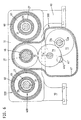
Fig. 13,14 zeigen die sechste Antriebsgruppe 600 der Auswerfereinheit 24. In Fig. 13 sind
um einen Ausgleichszylinder 112 herum zwei hydraulische Kolben-Zylinder-Einheiten angeordnet,
die die Auswerfereinheit 24 beaufschlagen, die auch als Kernzug ausgebildet sein
kann. Gerade bei dieser Ausführungsform können entweder anstelle der hydraulischen Kolben-Zylinder-Einheiten
elektromechanische Spindelantriebe eingesetzt oder z.B. die Oberfläche
des Ausgleichszylinders 112 zugleich als Primärelement eines Linearmotors verwendet
werden, wobei in zeichnerisch nicht dargestellter Weise eine mit dem Auswerfer 24 verbundene
Hülse das Sekundärelement sein kann. Entfällt mit der hydraulischen Lösung der
Ausgfeichzylinder, kann die Auswerfereinheit 24 auch gemäß Fig. 14 unmittelbar am beweglichen
Formträger 13 angeordnet werden. Die Auswerfereinheit 24 ist als eigenständige bauliche
Einheit ausgestaltet, wie dies aus der WO-A 97/12741 bekannt ist, deren Offenbarungsgehalt
hiermit insofern ausdrücklich zum Gegenstand der vorliegenden Anmeldung
gemacht wird. Der Antrieb ist dabei ein Hohlwellenmotor, der in sich das Betätigungselement
aufnimmt, wobei durch entsprechende Rotationsübertragungselemente diese Auswerfereinheit
als Ausschraubeinrichtung oder als Kernzug verwendbar ist. Anstelle eines derartigen
Auswerfers kann auch jeder beliebige andere Auswerfer eingesetzt werden, sofern sichergestellt
ist, daß ein Anschluß am beweglichen Formträger 13 möglich ist.13, 14 show the
Fig. 15 zeigt den Einsatz einer elektromechanischen Antriebseinheit als erste Baugruppe
100 und einer hydraulischen Einheit als Antriebsgruppe 200. Der Aufbau entspricht dem
Aufbau in der älteren Patentanmeldung 197 50 057.9. Der Schließmechanismus C treibt
über einen Riementrieb 81 die Antriebsstange 94 an. Die Antriebsstange 94 endet am Spindelkopf
95, der über Planeten 96 mit einem Gewinderohr 89 in Verbindung steht. Das Gewinderohr
89 ist stirnseitig durch ein Verschlußelement 97 verschlossen, so daß sich auch
hier der Eindruck einer Kolben-Zylinder-Einheit ergibt, da die Gewindeelemente äußerlich
unsichtbar sind. Der bewegliche Formträger ist zweigeteilt in die Teile 13',13", um zwischen
sich den Riementrieb 81 aufnehmen zu können. Die erste Antriebsgruppe 100 bringt das
Spritzgießwerkzeug M bis zum Formschluß. Durch Zuschalten der zweiten Antriebsgruppe
kommt die erste Antriebsgruppe 100 mit ihrem drehbaren Element 94 unter Verringerung des
Abstandes a in Anlage. Dies kann jederzeit während der Bewegung dadurch geschehen,
daß die Schaltkammer 98 mit Druck beaufschlagt wird, so daß das weitere Abstützelement
85, das hier ein Kolben ist, die Lagerhülse 83 in Fig. 15 nach links preßt. Bei Betätigung der
ersten Antriebsgruppe 100 wird der bewegliche Formträger 13',13 " bis zu einem beliebigen
Spalt zwischen den Formhälften oder bis zum Formschluß gefahren, wobei sich spätestens
bei Anlage der beiden Hälften der Gießform aneinander eine Kraft und damit eine Verformung
einstellt, die in Abhängigkeit des Kräfteverhältnisses zwischen der Schaltkammer 98
und der Druckkammer 99 zu einer früheren oder späteren Verringerung des Abstandes a zur
Anlage des Druckrohrs 93 am Spindelkopf 95 führt. Diese Anlage verhindert eine weitere
Rotation. Meist wird an einer beliebigen Stelle die Druckkammer 99 aktiv zugeschalten, so
daß, gleichgültig ob ein Formschluß bereits erreicht war oder nicht, die Schaltkammer 98
aktiv oder passiv entlastet wird. Das Druckrohr 93 ist mit dem als Kolben ausgebildeten weiteren
Abstützelement 85 verbunden. Die Lage des Druckrohrs ist durch den Druck in der
Schaltkammer 98 beeinflußbar. Bezüglich des weiteren Aufbaus und der Arbeitsweise dieser
Einrichtung wird auf die oben genannte ältere deutsche Patentanmeldung verwiesen.15 shows the use of an electromechanical drive unit as the
Zusammengefaßt können damit folgende unterschiedliche Antriebssysteme an einer Spritzgießmaschine
vorgesehen werden, wobei diese Auflistung keinen Anspruch auf Vollständigkeit
erhebt.
- hydraulisch mit Ölmotor (radial, axial, Zahnrad, Drehmoment)
- elektrisch mit konstantem Motor oder Regetmotor und Getriebe
- hydraulisch mit Zylinder
- elektrisch mit Umsetzung Rotation in Translation
- pneumatisch mit Zylinder
- elektrisch mit Linearmotor
- hydraulisch mit Zylinder
- elektrisch mit Umsetzung Rotation in Translation
- pneumatisch mit Zylinder
- elektrisch mit Linearmotor
- hydraulisch mit Zylinder
- pneumatisch mit Zylinder
- Elektromagnet
- Elektromotor Rotation in Translation
- elektrisch über Linearmotor
- hydraulisch mit Zylinder über Kniehebel oder unmittelbar
- elektrisch mit Umsetzung Rotation in Translation
- Linearmotor
- hydraulisch mit Zylinder über Kniehebel oder unmittelbar
- elektrisch mit Kniehebel oder Exzenter
- hydraulisch mit Zylinder
- pneumatisch mit Zylinder
- elektrisch mit Umsetzung Rotation in Translation
- elektrischer Linearmotor
- hydraulic with oil motor (radial, axial, gear, torque)
- electric with constant motor or regulating motor and gear
- hydraulic with cylinder
- electrical with implementation rotation in translation
- pneumatic with cylinder
- electrical with linear motor
- hydraulic with cylinder
- electrical with implementation rotation in translation
- pneumatic with cylinder
- electrical with linear motor
- hydraulic with cylinder
- pneumatic with cylinder
- electromagnet
- Electric motor rotation in translation
- electrically via linear motor
- hydraulic with cylinder via toggle lever or directly
- electrical with implementation rotation in translation
- linear motor
- hydraulic with cylinder via toggle lever or directly
- electrically with toggle or eccentric
- hydraulic with cylinder
- pneumatic with cylinder
- electrical with implementation rotation in translation
- electric linear motor
- 1010
- Trägerblockcarrier block
- 1111
- Plastifizierzylinderplasticizing
- 1212
- Fördermittelfunding
- 13,13',1313,13 ', 13
- " beweglicher Formträger"movable mold carrier
- 13a13a
- Ausnehmungrecess
- 13b13b
- Anlageflächecontact surface
- 14,14'14.14 '
- EinspritzbrückeInjection bridge
- 14a14a
- Anlagefläche'Contact surface '
- 14a'14a '
- Ausnehmungrecess
- 1515
- Lagerelement für 46Bearing element for 46
- 1616
- elektromechanischer Antriebelectromechanical drive
- 16a16a
- LinearbewegungsmittelLinear displacement means
- 16b16b
- Gewinderohrthreaded pipe
- 16c16c
- Spindelkopfspindle head
- 16d16d
- Planetenplanet
- 1717
- Lagerelement für 16aBearing element for 16a
- 1818
- Abstützungsupport
- 18a18a
- topfartige Ausnehmungpot-like recess
- 1919
- erstes Antriebselement von 500first drive element of 500
- 2020
- weiteres Antriebselement von 41another drive element from 41
- 21,4021.40
- Axial-LagerelementThrust bearing element
- 2222
- Gehäusedeckelhousing cover
- 2424
- Auswerfereinheitejector
- 2525
- erstes Abstützelementfirst support element
- 2626
- DruckübertragungselementPressure transmission element
- 2727
- Zylindercylinder
- 28,2928.29
- Zylinderkammercylinder chamber
- 3030
- Ringkolbenannular piston
- 3131
- HolmHolm
- 32,3332.33
- Zylinderdeckelcylinder cover
- 3434
- stationärer Formträgerstationary mold carrier
- 8383
- Lagerhülsebearing sleeve
- 8484
- WälzgewindeantriebWälzgewindeantrieb
- 8585
- weiteres Abstützelementadditional support element
- 8686
- FührungsholmHandlebar
- 8787
- Hydraulikblockhydraulic block
- 8888
- Lagerelementbearing element
- 8989
- Gewinderohr (Fig. 14)Threaded pipe (Fig. 14)
- 9090
- Kolben (Fig. 13)Piston (Fig. 13)
- 9191
- Ventilkolbenplunger
- 9292
- Begrenzungselementlimiting element
- 9393
- Druckrohrpressure pipe
- 9494
- Antriebsstangedrive rod
- 9595
- Spindelkopfspindle head
- 9696
- Planetenplanet
- 9797
- Verschlußelementclosure element
- 9898
- Schaltkammerswitching chamber
- 9999
- Druckkammerpressure chamber
- 100100
- erste Antriebsgruppefirst drive group
- 110110
- Zylindercylinder
- 111111
- Kolbenstangepiston rod
- 112112
- Ausgleichszylindercompensating cylinder
- 3535
- Maschinenfußmachine base
- 3636
- Bohrungdrilling
- 41,41',4141,41 ', 41
- " Dosierantrieb"Dosing drive
- 41a,41a'41a, 41a '
- Antriebswelledrive shaft
- 4242
- DüsenfahrantriebJet propulsion
- 4343
- EinspritzmittelInjection means
- 4545
- Verriegelungsmechanismuslocking mechanism
- 4646
- RotationsübertragungselementRotation transmitting member
- 46a46a
- Ausnehmungrecess
- 46b46b
- Abschnittsection
- 4747
- Getriebegehäusegearbox
- 4848
- Zylinderraum (Fig. 8)Cylinder space (Fig. 8)
- 4949
- Kolbenpiston
- 50,50'50.50 '
- Gestänge für 51Linkage for 51
- 50a50a
- Anschlußpunktconnection point
- 5151
- Düsennadelnozzle needle
- 5252
- Düsenkörpernozzle body
- 52a52a
- Düsenmündungnozzle orifice
- 5353
- Verbindungsmuffecoupling sleeve
- 5454
- Düseneinsatznozzle insert
- 5555
- Schwenkhebelpivoting lever
- 6060
- Zylindercylinder
- 61,6261.62
- Zylinderkammercylinder chamber
- 63,6463.64
- Zylinderdeckelcylinder cover
- 70,71,7270,71,72
- Ritzelpinion
- 71a,72a71a, 72a
- Achseaxis
- 72b72b
- Ritzelpinion
- 7575
- Sekundärelementsecondary element
- 8080
- Gehäusewandunghousing
- 8181
- Riementriebbelt drive
- 8282
- Kolben-Zylinder-EinheitPiston-cylinder unit
- 200-700200-700
- zweite bis siebte Antriebsgruppesecond to seventh drive group
- aa
- Abstanddistance
- a-aa-a
- Wirkachseeffective axis
- s-ss-s
- Spritzachseinjection axis
- CC
- Schließmechanismusclosing mechanism
- FF
- FormschließeinheitMold closing unit
- MM
- Spritzgießwerkzeuginjection mold
- PP
- Plastifiziereinheitplasticizing
- RR
- FormspannraumMold clamping area
- SS
- Spritzgießeinheitinjection molding
- MFMF
- MultifunktionselementMultifunctional element
Claims (19)
- Injection moulding machine for processing plastics materials and other plasticisable materials, having a modular structure comprising a plurality of driving groups, said machine havingcharacterised in that at least one of the driving groups (100, 300, 400, 500) is connectable to the injection moulding machine via at least one multifunctional element, which serves as an interface selectively for the connection of at least two different drive types selected from the group of electromechanical drives, hydraulic drives, pneumatic drives, linear motors or electromagnetic drives as the driving group with an otherwise unchanged injection moulding machine, whereby space is made available for the driving groups (100, 300, 400, 500), independently of the particular drive, on the injection moulding machine for accommodating each type of drive.a machine base (35),a mould closing unit (F) havinga stationary mould carrier (34) connected to the machine base (35),a movable mould carrier (13), which provides a mould clamping chamber (R) between itself and the stationary mould carrier (34),at least one injection moulding tool (M), the moulding parts of which can be accommodated in the mould clamping chamber (R) on the stationary mould carrier (34) and on the movable mould carrier (13),a closing mechanism (C) as a first driving group (100) for moving the movable mould carrier (13) towards the stationary mould carrier (34) and away from said stationary mould carrier so as to close the injection moulding tool (M), andforce transmitting means for transmitting substantially the closing force from the closing mechanism (C) to the stationary mould carrier (34),and an injection moulding unit (S), havinga plasticising unit (P), which comprises a plasticising cylinder (11) and a feeding means (12), which is accommodated in the plasticising cylinder, as well as a nozzle mouth (52a) on the end face, which mouth lies in an injection axis (s-s),a carrier block (10), which is disposed on the machine base (35) so as to be displaceable along the injection axis (s-s), and on which block the plasticising unit (P) is detachably mounted,an injection bridge (14),a metering drive (41,41') for the feeding means (12) of the plasticising unit (P) as a third driving group (300), which is connectable to the injection bridge (14),at least one nozzle moving drive (42), which is axis-parallel to the injection axis (s-s), as a fourth driving group (400) for moving the nozzle mouth (52a) towards the injection moulding tool (M) and away from said tool, andat least one injecting means (43), which is axis-parallel to the injection axis (s-s), as a fifth driving group (500) for the movement of the feeding means (12) relative to the plasticising cylinder (11),
- Injection moulding machine according to claim 1, characterised in that the closing mechanism comprises a first supporting element (25) for support purposes, and in that an arrangement, which is also connectable to the injection moulding machine via a multifunctional element, for applying the closing force is provided as the second driving group (200), as soon as the first driving group (100) has transferred the movable mould carrier to achieve the closure of the injection mould (M).
- Injection moulding machine according to claim 1 or 2, characterised in that an ejector unit (24) is provided as the sixth driving group (600), which is also connectable to one of the mould carriers (11,12) via a multifunctional element.
- Injection moulding machine according to claim 3, characterised in that even the ejector (24), as a core puller, can communicate with the multifunctional element, which communicates with the ejector unit (24).
- Injection moulding machine according to one of claims 1 to 4, characterised in that a drive for the nozzle needle (51) of a closable nozzle body (52) is provided as the seventh driving group (700), which drive is also connectable to the injection moulding machine via a multifunctional element.
- Injection moulding machine according to one of the preceding claims, characterised in that, on the side of the injection moulding unit, the injection bridge (14') and a rotation transmitting element (46), which is rotatably mounted therein, for transmitting the rotation of a metering drive (41,41') for the third driving group (300) are configured as multifunctional elements.
- Injection moulding machine according to claim 6, characterised in that the rotation transmitting element (46) has a recess (46a), in which the drive shaft (41a) of the metering drive (41) engages for the operative connection, the metering drive (41) being an hydraulic rotary motor or an electrically operated high-torque motor.
- Injection moulding machine according to claim 6 or 7, characterised in that the rotation transmitting element (46) protrudes from the injection bridge (14') with a portion (46b), to which a transmission housing (47), with an associated transmission, is connectable, which transmission is driven by a metering drive (41').
- Injection moulding machine according to one of claims 1 to 5, characterised in that the injection bridge (14) has an abutment face (14a) as the multifunctional element for the fifth driving group (500), which face serves as an abutment for a pressure transmitting element, which is configured as injecting means (43) and is supported on a support (18), which communicates with the injection bridge (14), said pressure transmitting element preferably being hydraulically or electromechanically displaceable as injecting means (43).
- Injection moulding machine according to claim 9, characterised in that the support (18) has a cup-like recess (18a), which either forms a cylinder chamber (48) for the injecting means (43), which is configured as piston (49), or accommodates a non-rotatable part of an electromechanical spindle drive, which co-operates with a rotatable part mounted on the injection bridge (14).
- Injection moulding machine according to claim 9 or 10, characterised in that there is non-rotatably accommodated in a cup-like recess (18a) of the support (18) a threaded tube (16b) which co-operates with a spindle head (16c), the spindle head (16c) being disposed on the end of a linear moving means (16a), which centrally penetrates the pressure transmitting element, configured as tube (26), and which is rotatable via a first driving element (19) disposed in the injection bridge (14).
- Injection moulding machine according to one of the preceding claims, characterised in that a driving element (20), which is coaxial with a first driving element (19) for the injecting means (43), is disposed in the injection bridge (14) for the rotation of the feeding means.
- Injection moulding machine according to claim 11 or 12, characterised in that there is provided between first driving element (19) and additional driving element (20) an axial bearing element (21) which, on the one hand, serves as the force transmitting element and, on the other hand, serves as the separating means between the driving elements (19,20).
- Injection moulding machine according to one of the preceding claims, characterised in that the cylinder covers (32,33), which are disposed on the guide bars (31) configured as the force transmitting means, are configured as the multifunctional element for the fourth driving group (400), which covers accommodate therebetween the cylinder (27), which is configured either as the cylinder for an hydraulic annular piston (30) or as the wall for a secondary element (75) of a linear motor.
- Injection moulding machine according to one of the preceding claims, characterised in that a cylinder (27) of the fourth driving group (400) is configured on the outside as the multifunctional element for the fifth driving group (500) and serves as a guide for the injection bridge (14,14').
- Injection moulding machine according to claim 15, characterised in that the cylinder (27) is the piston rod for an hydraulic injecting means (43).
- Injection moulding machine according to claim 5, characterised in that a housing wall (80) is mounted on the carrier block (10) as the multifunctional element for the attachment of the seventh driving group (700) for actuating the nozzle needle (51), which wall is either penetrated by the rod assembly (50) for actuating the nozzle needle (51) when an hydraulic actuation is effected, or is operatively connected to another rod assembly (50') via a rolling thread drive (84), the housing wall (80) serving as the housing for said drive.
- Injection moulding machine according to one of the preceding claims, characterised in that the movable mould carrier (13) has, as the multifunctional element for the first and second driving groups (100,200), a recess (13a) which either has a base supporting a threaded tube (89) of an electromechanical drive or accommodates a part of an hydraulic piston (90), the cylinder (110) of said piston being secured on the edge of the recess (13a).
- Injection moulding machine according to one of claims 2 to 17, characterised in that there is disposed between first supporting element (25) and movable mould carrier (13;13',13") an additional supporting element (85) as the multifunctional element, which is actuatable via a switching chamber (98) actuatable with hydraulic medium, the switching chamber (98) permitting the movement of the first driving group (100) when it is under pressure, while the switching chamber (98) blocks the movement of the first driving group (100) when the switching chamber (98) is free of pressure, the pressure of the hydraulic medium in the switching chamber (98) being connectable in exactly the same way as the second driving group (200).
Applications Claiming Priority (3)
| Application Number | Priority Date | Filing Date | Title |
|---|---|---|---|
| DE19847298 | 1998-10-14 | ||
| DE19847298A DE19847298C2 (en) | 1998-10-14 | 1998-10-14 | Injection molding machine with a modular structure comprising several drive groups |
| PCT/EP1999/007582 WO2000021729A1 (en) | 1998-10-14 | 1999-10-09 | Injection molding machine having a modular construction which comprises a plurality of drive groups |
Publications (3)
| Publication Number | Publication Date |
|---|---|
| EP1121237A1 EP1121237A1 (en) | 2001-08-08 |
| EP1121237B1 true EP1121237B1 (en) | 2002-12-11 |
| EP1121237B2 EP1121237B2 (en) | 2010-08-04 |
Family
ID=7884405
Family Applications (1)
| Application Number | Title | Priority Date | Filing Date |
|---|---|---|---|
| EP99952546A Expired - Lifetime EP1121237B2 (en) | 1998-10-14 | 1999-10-09 | Injection molding machine having a modular construction which comprises a plurality of drive groups |
Country Status (7)
| Country | Link |
|---|---|
| US (1) | US6517337B1 (en) |
| EP (1) | EP1121237B2 (en) |
| JP (1) | JP2002527256A (en) |
| AT (1) | ATE229422T1 (en) |
| CA (1) | CA2347458C (en) |
| DE (2) | DE19847298C2 (en) |
| WO (1) | WO2000021729A1 (en) |
Cited By (1)
| Publication number | Priority date | Publication date | Assignee | Title |
|---|---|---|---|---|
| DE10309906B3 (en) * | 2003-02-25 | 2004-06-09 | Karl Hehl | Mold closing mechanism, at an injection molding machine, is on a support at the machine foot with an angular adjustment, to give an accurate alignment of the mold carriers |
Families Citing this family (22)
| Publication number | Priority date | Publication date | Assignee | Title |
|---|---|---|---|---|
| DE10022192A1 (en) * | 2000-05-03 | 2001-11-15 | Mannesmann Ag | Device for removing injection molded parts |
| DE50201729D1 (en) * | 2001-02-15 | 2005-01-13 | Mannesmann Plastics Machinery | LOCKING DEVICE IN AN INJECTION MOLDING MACHINE FOR PLASTICS |
| AT5362U1 (en) | 2001-05-11 | 2002-06-25 | Engel Gmbh Maschbau | DEVICE FOR INJECTION MOLDING PLASTIC |
| CN100457419C (en) | 2002-10-31 | 2009-02-04 | 住友重机械工业株式会社 | Molding machine and control method thereof |
| DE102004033690A1 (en) * | 2004-07-09 | 2006-02-16 | Demag Ergotech Gmbh | Injection molding machine |
| DE102004057164A1 (en) * | 2004-11-26 | 2006-06-01 | Krauss-Maffei Kunststofftechnik Gmbh | injection molding machine |
| DE202005021060U1 (en) * | 2005-09-14 | 2007-01-18 | Siemens Ag | Injection molding machine, especially for injection stamping, comprises an injection unit with a linear drive unit, a closure unit with a linear drive unit, and a preplastication unit |
| USD559285S1 (en) * | 2005-10-03 | 2008-01-08 | Galomb David E | Injection molding machine |
| US7772266B2 (en) | 2006-02-15 | 2010-08-10 | Dendreon Corporation | Small-molecule modulators of TRP-P8 activity |
| US20070296121A1 (en) * | 2006-06-07 | 2007-12-27 | Husky Injection Molding Systems Ltd. | Molding-system drive |
| US20070296281A1 (en) * | 2006-06-07 | 2007-12-27 | Husky Injection Molding Systems Ltd. | Electrical motor |
| US7695266B2 (en) * | 2006-11-02 | 2010-04-13 | Husky Injection Molding Systems Ltd. | Molding structure |
| DE102007042643A1 (en) | 2007-09-07 | 2009-04-02 | Siemens Ag | Method for operating an injection device for an injection molding machine, injection device and injection molding machine with such an injection device |
| GB2478732B (en) | 2010-03-15 | 2014-08-20 | Kraft Foods R & D Inc | Improvements in injection moulding |
| CN102211383B (en) * | 2010-04-01 | 2013-11-06 | 永高股份有限公司 | Secondary slide block core pulling mechanism for plastic mould |
| DE102010046275A1 (en) * | 2010-09-22 | 2012-03-22 | Netstal-Maschinen Ag | Universal auxiliary control for an injection molding machine |
| JP5980865B2 (en) * | 2014-09-11 | 2016-08-31 | ファナック株式会社 | Injection molding machine |
| DE102016205554B4 (en) * | 2016-04-04 | 2022-02-24 | Rekers Gmbh Maschinen- Und Anlagenbau | Mandrel device for a block molding machine, block molding machine and method for producing shaped blocks |
| JP6867978B2 (en) * | 2018-06-13 | 2021-05-12 | 日精樹脂工業株式会社 | Injection molding machine and its molding method |
| JP7605574B2 (en) * | 2021-06-14 | 2024-12-24 | 株式会社日本製鋼所 | Injection unit and injection molding machine |
| DE102024131208A1 (en) | 2024-10-25 | 2026-04-30 | Arburg Gmbh + Co Kg | Modular plastics processing machine |
| DE102024131207B3 (en) * | 2024-10-25 | 2025-11-27 | Arburg Gmbh + Co Kg | Injection molding unit for processing plastics, injection molding machine equipped with it and associated kit |
Family Cites Families (6)
| Publication number | Priority date | Publication date | Assignee | Title |
|---|---|---|---|---|
| DE2247386A1 (en) † | 1972-09-27 | 1974-03-28 | Demag Ag | Injection moulding machine rotary drive for screw - with hydraulic forward drive, having shaft coupling permitting use of different types of motor |
| EP0576925B1 (en) * | 1992-06-23 | 1997-08-20 | Battenfeld Kunststoffmaschinen Ges.m.b.H. | Injection unit for injection moulding machines |
| DE19536565C2 (en) | 1995-10-02 | 1998-07-16 | Karl Hehl | Injection molding machine for processing plasticizable materials |
| DE19536567C2 (en) | 1995-10-02 | 1998-12-17 | Karl Hehl | Mold clamping unit with a device for the treatment and / or removal of molded parts |
| DE19731833C1 (en) * | 1997-07-24 | 1999-01-14 | Karl Hehl | Injection molding unit for an injection molding machine |
| DE19750057C2 (en) | 1997-11-12 | 2000-08-03 | Karl Hehl | Mold clamping unit for an injection molding machine |
-
1998
- 1998-10-14 DE DE19847298A patent/DE19847298C2/en not_active Expired - Fee Related
-
1999
- 1999-10-09 WO PCT/EP1999/007582 patent/WO2000021729A1/en not_active Ceased
- 1999-10-09 DE DE59903783T patent/DE59903783D1/en not_active Expired - Lifetime
- 1999-10-09 JP JP2000575673A patent/JP2002527256A/en active Pending
- 1999-10-09 AT AT99952546T patent/ATE229422T1/en active
- 1999-10-09 EP EP99952546A patent/EP1121237B2/en not_active Expired - Lifetime
- 1999-10-09 CA CA002347458A patent/CA2347458C/en not_active Expired - Fee Related
- 1999-10-09 US US09/807,395 patent/US6517337B1/en not_active Expired - Lifetime
Cited By (1)
| Publication number | Priority date | Publication date | Assignee | Title |
|---|---|---|---|---|
| DE10309906B3 (en) * | 2003-02-25 | 2004-06-09 | Karl Hehl | Mold closing mechanism, at an injection molding machine, is on a support at the machine foot with an angular adjustment, to give an accurate alignment of the mold carriers |
Also Published As
| Publication number | Publication date |
|---|---|
| EP1121237A1 (en) | 2001-08-08 |
| DE59903783D1 (en) | 2003-01-23 |
| DE19847298C2 (en) | 2000-11-02 |
| CA2347458A1 (en) | 2000-04-20 |
| EP1121237B2 (en) | 2010-08-04 |
| JP2002527256A (en) | 2002-08-27 |
| US6517337B1 (en) | 2003-02-11 |
| CA2347458C (en) | 2008-11-25 |
| WO2000021729A1 (en) | 2000-04-20 |
| DE19847298A1 (en) | 2000-04-27 |
| ATE229422T1 (en) | 2002-12-15 |
Similar Documents
| Publication | Publication Date | Title |
|---|---|---|
| EP1121237B1 (en) | Injection molding machine having a modular construction which comprises a plurality of drive groups | |
| EP2726267B1 (en) | Rotation device for an injection-molding device | |
| DE2055261C3 (en) | Plastic injection molding machine for the production of injection molded parts consisting of two different plastic compounds | |
| DE2113414A1 (en) | Closing, locking and preloading device for casting molds | |
| DE19920626C2 (en) | Injection molding machine for processing plastics | |
| EP0508277B1 (en) | Drive apparatus for the displacement and/or the positioning force for injection moulding machines | |
| EP1284849A1 (en) | Injection unit for injection moulding machines with a continuously functioning plasticizing unit | |
| EP1097035B1 (en) | Injection molding unit for an injection molding machine | |
| EP1339537B1 (en) | Injection unit for an injection moulding machine | |
| EP1768828B1 (en) | Injection moulding machine | |
| EP3710222B1 (en) | Mold-closing unit for an injection molding machine, and method for locking a force transmission element | |
| EP0576837B1 (en) | Injection mouding machine with stack mould | |
| AT525797B1 (en) | Toggle clamp unit and method of mold closing and mold opening | |
| EP3672776B1 (en) | Mould-closing unit for an injection moulding machine, and method for locking a force transmission element | |
| EP0107778B1 (en) | Method and apparatus for the treatment of plastifiable material | |
| EP3959058B1 (en) | Injection molding unit for an injection molding machine for processing plastics | |
| EP0585671B1 (en) | Ejection unit for injection moulding machines | |
| EP1802441B1 (en) | Closing unit for an injection moulding machine comprising a stack mould | |
| DE60108432T2 (en) | Drive device for injection molding machine | |
| EP4458547A1 (en) | Mould closing unit and method for operating a mould closing unit of a machine for processing plastics | |
| DE19605747C2 (en) | Drive unit for plasticizing and injection units of plastic injection molding machines | |
| DE19535081C2 (en) | Two-plate injection molding machine | |
| EP2719517B1 (en) | Injection moulding machine | |
| DE19712494C2 (en) | Piston spraying device with screw pre-plastification | |
| DE10040322B4 (en) | Plastic injection molding machine and drive device for a plastic injection molding machine |
Legal Events
| Date | Code | Title | Description |
|---|---|---|---|
| PUAI | Public reference made under article 153(3) epc to a published international application that has entered the european phase |
Free format text: ORIGINAL CODE: 0009012 |
|
| 17P | Request for examination filed |
Effective date: 20010320 |
|
| AK | Designated contracting states |
Kind code of ref document: A1 Designated state(s): AT BE CH CY DE DK ES FI FR GB GR IE IT LI LU MC NL PT SE |
|
| GRAG | Despatch of communication of intention to grant |
Free format text: ORIGINAL CODE: EPIDOS AGRA |
|
| 17Q | First examination report despatched |
Effective date: 20020102 |
|
| GRAG | Despatch of communication of intention to grant |
Free format text: ORIGINAL CODE: EPIDOS AGRA |
|
| GRAH | Despatch of communication of intention to grant a patent |
Free format text: ORIGINAL CODE: EPIDOS IGRA |
|
| GRAH | Despatch of communication of intention to grant a patent |
Free format text: ORIGINAL CODE: EPIDOS IGRA |
|
| GRAA | (expected) grant |
Free format text: ORIGINAL CODE: 0009210 |
|
| AK | Designated contracting states |
Kind code of ref document: B1 Designated state(s): AT CH DE FR GB IT LI |
|
| REF | Corresponds to: |
Ref document number: 229422 Country of ref document: AT Date of ref document: 20021215 Kind code of ref document: T |
|
| REG | Reference to a national code |
Ref country code: GB Ref legal event code: FG4D Free format text: NOT ENGLISH |
|
| REG | Reference to a national code |
Ref country code: CH Ref legal event code: EP |
|
| REG | Reference to a national code |
Ref country code: CH Ref legal event code: NV Representative=s name: LUCHS & PARTNER PATENTANWAELTE |
|
| REF | Corresponds to: |
Ref document number: 59903783 Country of ref document: DE Date of ref document: 20030123 |
|
| GBT | Gb: translation of ep patent filed (gb section 77(6)(a)/1977) |
Effective date: 20030307 |
|
| ET | Fr: translation filed | ||
| PLBQ | Unpublished change to opponent data |
Free format text: ORIGINAL CODE: EPIDOS OPPO |
|
| PLBI | Opposition filed |
Free format text: ORIGINAL CODE: 0009260 |
|
| 26 | Opposition filed |
Opponent name: ENGEL AUSTRIA GMBH Effective date: 20030905 |
|
| PLAX | Notice of opposition and request to file observation + time limit sent |
Free format text: ORIGINAL CODE: EPIDOSNOBS2 |
|
| PLAX | Notice of opposition and request to file observation + time limit sent |
Free format text: ORIGINAL CODE: EPIDOSNOBS2 |
|
| PLAX | Notice of opposition and request to file observation + time limit sent |
Free format text: ORIGINAL CODE: EPIDOSNOBS2 |
|
| PLBB | Reply of patent proprietor to notice(s) of opposition received |
Free format text: ORIGINAL CODE: EPIDOSNOBS3 |
|
| PLAY | Examination report in opposition despatched + time limit |
Free format text: ORIGINAL CODE: EPIDOSNORE2 |
|
| PLBC | Reply to examination report in opposition received |
Free format text: ORIGINAL CODE: EPIDOSNORE3 |
|
| PGFP | Annual fee paid to national office [announced via postgrant information from national office to epo] |
Ref country code: GB Payment date: 20061024 Year of fee payment: 8 |
|
| PLAB | Opposition data, opponent's data or that of the opponent's representative modified |
Free format text: ORIGINAL CODE: 0009299OPPO |
|
| R26 | Opposition filed (corrected) |
Opponent name: ENGEL AUSTRIA GMBH Effective date: 20030905 |
|
| APBP | Date of receipt of notice of appeal recorded |
Free format text: ORIGINAL CODE: EPIDOSNNOA2O |
|
| APAH | Appeal reference modified |
Free format text: ORIGINAL CODE: EPIDOSCREFNO |
|
| APBQ | Date of receipt of statement of grounds of appeal recorded |
Free format text: ORIGINAL CODE: EPIDOSNNOA3O |
|
| GBPC | Gb: european patent ceased through non-payment of renewal fee |
Effective date: 20071009 |
|
| PG25 | Lapsed in a contracting state [announced via postgrant information from national office to epo] |
Ref country code: GB Free format text: LAPSE BECAUSE OF NON-PAYMENT OF DUE FEES Effective date: 20071009 |
|
| APBU | Appeal procedure closed |
Free format text: ORIGINAL CODE: EPIDOSNNOA9O |
|
| PUAH | Patent maintained in amended form |
Free format text: ORIGINAL CODE: 0009272 |
|
| STAA | Information on the status of an ep patent application or granted ep patent |
Free format text: STATUS: PATENT MAINTAINED AS AMENDED |
|
| 27A | Patent maintained in amended form |
Effective date: 20100804 |
|
| AK | Designated contracting states |
Kind code of ref document: B2 Designated state(s): AT CH DE FR GB IT LI |
|
| REG | Reference to a national code |
Ref country code: CH Ref legal event code: AEN Free format text: AUFRECHTERHALTUNG DES PATENTES IN GEAENDERTER FORM |
|
| PGFP | Annual fee paid to national office [announced via postgrant information from national office to epo] |
Ref country code: FR Payment date: 20111103 Year of fee payment: 13 |
|
| REG | Reference to a national code |
Ref country code: FR Ref legal event code: ST Effective date: 20130628 |
|
| PG25 | Lapsed in a contracting state [announced via postgrant information from national office to epo] |
Ref country code: FR Free format text: LAPSE BECAUSE OF NON-PAYMENT OF DUE FEES Effective date: 20121031 |
|
| PGFP | Annual fee paid to national office [announced via postgrant information from national office to epo] |
Ref country code: IT Payment date: 20131030 Year of fee payment: 15 |
|
| REG | Reference to a national code |
Ref country code: DE Ref legal event code: R082 Ref document number: 59903783 Country of ref document: DE Representative=s name: PATENTANWAELTE REINHARDT & POHLMANN PARTNERSCH, DE |
|
| REG | Reference to a national code |
Ref country code: DE Ref legal event code: R082 Ref document number: 59903783 Country of ref document: DE Representative=s name: RPK PATENTANWAELTE REINHARDT, POHLMANN UND KAU, DE Effective date: 20140731 Ref country code: DE Ref legal event code: R082 Ref document number: 59903783 Country of ref document: DE Representative=s name: PATENTANWAELTE REINHARDT & POHLMANN PARTNERSCH, DE Effective date: 20140731 Ref country code: DE Ref legal event code: R081 Ref document number: 59903783 Country of ref document: DE Owner name: KEINATH, RENATE, DE Free format text: FORMER OWNER: HEHL, KARL, 72290 LOSSBURG, VERSTORBEN, DE Effective date: 20140731 |
|
| PG25 | Lapsed in a contracting state [announced via postgrant information from national office to epo] |
Ref country code: IT Free format text: LAPSE BECAUSE OF NON-PAYMENT OF DUE FEES Effective date: 20141009 |
|
| PGFP | Annual fee paid to national office [announced via postgrant information from national office to epo] |
Ref country code: CH Payment date: 20151026 Year of fee payment: 17 |
|
| PGFP | Annual fee paid to national office [announced via postgrant information from national office to epo] |
Ref country code: DE Payment date: 20160805 Year of fee payment: 18 |
|
| PGFP | Annual fee paid to national office [announced via postgrant information from national office to epo] |
Ref country code: AT Payment date: 20161024 Year of fee payment: 18 |
|
| REG | Reference to a national code |
Ref country code: CH Ref legal event code: PL |
|
| PG25 | Lapsed in a contracting state [announced via postgrant information from national office to epo] |
Ref country code: CH Free format text: LAPSE BECAUSE OF NON-PAYMENT OF DUE FEES Effective date: 20161031 Ref country code: LI Free format text: LAPSE BECAUSE OF NON-PAYMENT OF DUE FEES Effective date: 20161031 |
|
| REG | Reference to a national code |
Ref country code: DE Ref legal event code: R119 Ref document number: 59903783 Country of ref document: DE |
|
| REG | Reference to a national code |
Ref country code: AT Ref legal event code: MM01 Ref document number: 229422 Country of ref document: AT Kind code of ref document: T Effective date: 20171009 |
|
| PG25 | Lapsed in a contracting state [announced via postgrant information from national office to epo] |
Ref country code: DE Free format text: LAPSE BECAUSE OF NON-PAYMENT OF DUE FEES Effective date: 20180501 |
|
| PG25 | Lapsed in a contracting state [announced via postgrant information from national office to epo] |
Ref country code: AT Free format text: LAPSE BECAUSE OF NON-PAYMENT OF DUE FEES Effective date: 20171009 |