EP1121237B1 - Spritzgiessmaschine mit einem mehrere antriebsgruppen umfassenden modularen aufbau - Google Patents
Spritzgiessmaschine mit einem mehrere antriebsgruppen umfassenden modularen aufbau Download PDFInfo
- Publication number
- EP1121237B1 EP1121237B1 EP99952546A EP99952546A EP1121237B1 EP 1121237 B1 EP1121237 B1 EP 1121237B1 EP 99952546 A EP99952546 A EP 99952546A EP 99952546 A EP99952546 A EP 99952546A EP 1121237 B1 EP1121237 B1 EP 1121237B1
- Authority
- EP
- European Patent Office
- Prior art keywords
- drive
- injection moulding
- injection
- moulding machine
- cylinder
- Prior art date
- Legal status (The legal status is an assumption and is not a legal conclusion. Google has not performed a legal analysis and makes no representation as to the accuracy of the status listed.)
- Expired - Lifetime
Links
- 238000001746 injection moulding Methods 0.000 title claims abstract description 72
- 238000010276 construction Methods 0.000 title description 2
- 238000002347 injection Methods 0.000 claims description 61
- 239000007924 injection Substances 0.000 claims description 61
- 230000005540 biological transmission Effects 0.000 claims description 26
- 230000007246 mechanism Effects 0.000 claims description 14
- 239000000463 material Substances 0.000 claims description 5
- 239000004033 plastic Substances 0.000 claims description 4
- 229920003023 plastic Polymers 0.000 claims description 4
- 239000000969 carrier Substances 0.000 claims description 3
- 238000012545 processing Methods 0.000 claims description 3
- 238000000465 moulding Methods 0.000 claims description 2
- 238000005096 rolling process Methods 0.000 claims 1
- 238000013519 translation Methods 0.000 description 22
- 239000007921 spray Substances 0.000 description 6
- 239000000919 ceramic Substances 0.000 description 2
- 239000000243 solution Substances 0.000 description 2
- 241000196324 Embryophyta Species 0.000 description 1
- 235000003332 Ilex aquifolium Nutrition 0.000 description 1
- 241000209027 Ilex aquifolium Species 0.000 description 1
- 230000004308 accommodation Effects 0.000 description 1
- 230000009286 beneficial effect Effects 0.000 description 1
- 238000005266 casting Methods 0.000 description 1
- 230000008859 change Effects 0.000 description 1
- 239000003795 chemical substances by application Substances 0.000 description 1
- 230000008878 coupling Effects 0.000 description 1
- 238000010168 coupling process Methods 0.000 description 1
- 238000005859 coupling reaction Methods 0.000 description 1
- 238000006073 displacement reaction Methods 0.000 description 1
- 238000005553 drilling Methods 0.000 description 1
- 238000003780 insertion Methods 0.000 description 1
- 230000037431 insertion Effects 0.000 description 1
- 238000005461 lubrication Methods 0.000 description 1
- 238000004519 manufacturing process Methods 0.000 description 1
- 238000000034 method Methods 0.000 description 1
- 238000003825 pressing Methods 0.000 description 1
- 230000008569 process Effects 0.000 description 1
- 230000002035 prolonged effect Effects 0.000 description 1
- 230000001681 protective effect Effects 0.000 description 1
- 230000001105 regulatory effect Effects 0.000 description 1
- 238000005507 spraying Methods 0.000 description 1
- 238000012546 transfer Methods 0.000 description 1
Images


Classifications
-
- B—PERFORMING OPERATIONS; TRANSPORTING
- B29—WORKING OF PLASTICS; WORKING OF SUBSTANCES IN A PLASTIC STATE IN GENERAL
- B29C—SHAPING OR JOINING OF PLASTICS; SHAPING OF MATERIAL IN A PLASTIC STATE, NOT OTHERWISE PROVIDED FOR; AFTER-TREATMENT OF THE SHAPED PRODUCTS, e.g. REPAIRING
- B29C45/00—Injection moulding, i.e. forcing the required volume of moulding material through a nozzle into a closed mould; Apparatus therefor
- B29C45/17—Component parts, details or accessories; Auxiliary operations
- B29C45/46—Means for plasticising or homogenising the moulding material or forcing it into the mould
- B29C45/47—Means for plasticising or homogenising the moulding material or forcing it into the mould using screws
- B29C45/50—Axially movable screw
- B29C45/5008—Drive means therefor
-
- B—PERFORMING OPERATIONS; TRANSPORTING
- B29—WORKING OF PLASTICS; WORKING OF SUBSTANCES IN A PLASTIC STATE IN GENERAL
- B29C—SHAPING OR JOINING OF PLASTICS; SHAPING OF MATERIAL IN A PLASTIC STATE, NOT OTHERWISE PROVIDED FOR; AFTER-TREATMENT OF THE SHAPED PRODUCTS, e.g. REPAIRING
- B29C45/00—Injection moulding, i.e. forcing the required volume of moulding material through a nozzle into a closed mould; Apparatus therefor
- B29C45/03—Injection moulding apparatus
- B29C45/07—Injection moulding apparatus using movable injection units
-
- B—PERFORMING OPERATIONS; TRANSPORTING
- B29—WORKING OF PLASTICS; WORKING OF SUBSTANCES IN A PLASTIC STATE IN GENERAL
- B29C—SHAPING OR JOINING OF PLASTICS; SHAPING OF MATERIAL IN A PLASTIC STATE, NOT OTHERWISE PROVIDED FOR; AFTER-TREATMENT OF THE SHAPED PRODUCTS, e.g. REPAIRING
- B29C45/00—Injection moulding, i.e. forcing the required volume of moulding material through a nozzle into a closed mould; Apparatus therefor
- B29C45/17—Component parts, details or accessories; Auxiliary operations
- B29C45/20—Injection nozzles
- B29C45/23—Feed stopping equipment
- B29C45/231—Needle valve systems therefor
-
- B—PERFORMING OPERATIONS; TRANSPORTING
- B29—WORKING OF PLASTICS; WORKING OF SUBSTANCES IN A PLASTIC STATE IN GENERAL
- B29C—SHAPING OR JOINING OF PLASTICS; SHAPING OF MATERIAL IN A PLASTIC STATE, NOT OTHERWISE PROVIDED FOR; AFTER-TREATMENT OF THE SHAPED PRODUCTS, e.g. REPAIRING
- B29C45/00—Injection moulding, i.e. forcing the required volume of moulding material through a nozzle into a closed mould; Apparatus therefor
- B29C45/17—Component parts, details or accessories; Auxiliary operations
- B29C45/40—Removing or ejecting moulded articles
- B29C45/4005—Ejector constructions; Ejector operating mechanisms
-
- B—PERFORMING OPERATIONS; TRANSPORTING
- B29—WORKING OF PLASTICS; WORKING OF SUBSTANCES IN A PLASTIC STATE IN GENERAL
- B29C—SHAPING OR JOINING OF PLASTICS; SHAPING OF MATERIAL IN A PLASTIC STATE, NOT OTHERWISE PROVIDED FOR; AFTER-TREATMENT OF THE SHAPED PRODUCTS, e.g. REPAIRING
- B29C45/00—Injection moulding, i.e. forcing the required volume of moulding material through a nozzle into a closed mould; Apparatus therefor
- B29C45/17—Component parts, details or accessories; Auxiliary operations
- B29C45/64—Mould opening, closing or clamping devices
- B29C45/68—Mould opening, closing or clamping devices hydro-mechanical
Definitions
- the invention relates to an injection molding machine for processing plastics and others plastifiable masses such as ceramic or powdery masses with one of several drive groups comprehensive modular structure according to the preamble of claim 1.
- Such a modular structure is in its entirety from the prior art not known, but it is known from EP 0 576 925 A1, for example, within individual Drive groups of an injection molding machine both on the side of the injection molding unit and also to provide liquid-cooled electric servomotors on the form-locking side.
- motors of this type can be used in any way on an injection molding machine, however, it is necessary to use the respective connection elements on the injection molding machine to be replaced if other types of drives are used.
- Extensive parts must therefore be kept in stock in order to meet To build customers' machines accordingly. This leads to prolonged Delivery times.
- the present invention is based on the object the structural requirements for an injection molding machine of the type mentioned at the beginning to create an increased modularity using largely identical Components.
- a rotation transmission element may be provided in the injection bridge, the It is both intended that a rotary motor is connected to the rear or to elsewhere a drive wheel can be set so that this via a gear Element is controllable. There is sufficient space for all drives Injection molding machine provided.
- Structural elements can be provided in the injection bridge, depending on the type of drive are even passive and are not needed at all, but on the other hand the possibility create; easily change the drive type.
- the for the different Required types of drive can be obtained by being in a confined space have these components combined for the different drive types combined.
- the movable mold carrier can be designed in this way on the mold-closing side; that to the same Components both electromechanical drives and hydraulic or pneumatic drives can be connected. It should not be underestimated that the component in this respect for the different requirements must be prepared, the tightness for the hydraulics the force transmission must be ensured as well as for the electromechanical drive.
- the injection molding machine is used e.g. as a plastic injection molding machine processing plasticizable Masses such as of plastics, powdery or ceramic masses.
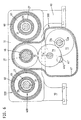
- the 16 has a modular structure with several drive groups, which are partly assigned to the mold clamping unit F and partly to the injection molding unit S. Mold clamping unit F and injection molding unit are arranged on the machine base 35.
- the mold clamping unit F has a stationary mold carrier 34 and a movable one Mold carrier 13.
- a mold clamping space R is formed between the two mold carriers, in the molded parts of an injection mold M or an injection mold on the stationary Mold carrier 34 and on the movable mold carrier 13 are added.
- the mold clamping unit has a locking mechanism C, which at the same time the first drive group 100 Moving the movable mold carrier to and from the stationary mold carrier 34 represents away.
- a first support element is provided to support the locking mechanism C. 25 provided, with "serial closing" also provided a further support element can be. During this serial closing, the Movable mold carriers transferred to form closure, while by a separate drive group the closing force is applied.
- the second drive group 200 which is used in particular when the first Drive group 100 the movable mold carrier 13 until the mold of the injection mold M convicted. If necessary, however, the first drive group 100 can be combined with the second Drive group 200 combined can be formed by one and the same drive group what e.g. is possible in particular with a hydraulic solution.
- Power transmission means intended. These power transmission means are the spars 86, which at the same time Closing mechanism C and the movable mold carrier 13 serve as a guide.
- Power transmission element can also be provided, such as e.g. so-called "C-bracket", which around the forces occurring during closing and injection molding Mold clamping space R around from the stationary mold carrier 34 to the movable mold carrier 13 conduct as is known to those skilled in the art.
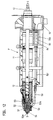
- the injection molding unit S has a plasticizing unit P, which has a plasticizing cylinder 11 and a conveying means 12 received in the plasticizing cylinder. face side the injection molding unit ends with a nozzle body 52 which has a nozzle orifice 52a, which lies in a spray axis s-s (Fig. 11, 12).
- the plasticizing unit P is on one the carrier base 10 movably arranged along the spray axis s-s releasably attached.
- the injection molding unit S further comprises an injection bridge 14 and a metering drive 41, 41 ', 41 "for the conveying means 12 and the plasticizing unit P as the third drive group 300, which can be connected to the injection bridge 14.
- the metering drive is used in particular for rotating of the funding, since this funding is usually a screw conveyor. Will be here Provided delivery pistons, the third drive group 300 falls with the injection center 43 of the fifth drive group 500 together.
- the injection means is at least one drive parallel to the spray axis s-s - mostly for Achieving a symmetrical introduction of force, however, several drives - provided that as a fifth drive group 500 for the relative movement of the conveying means 12 with respect to the Plasticizing cylinder 11 is used.
- This axial movement of the conveyor means that before Conveyor screw located plasticized material in the mold cavity of the injection mold M injected.
- the fourth drive group 400 s-s parallel-axis nozzle travel drive 42 is provided.
- the plasticized material injected into the mold cavity When the plasticized material injected into the mold cavity has hardened, it becomes a molding ejected via an ejector unit 24, which is located anywhere in the injection molding machine, however, it is usually arranged in the injection axis s-s on the form-locking side.
- the Ejector unit 24 can, however, also be designed as a core pull.
- the drive from the ejector unit 24 or core pull is carried out via a sixth drive group 600.
- a seventh drive group 700 is provided, via which a nozzle needle 51 can be controlled via a linkage 50 around the nozzle mouth 52a in the case of a closure nozzle to close if necessary.
- Multifunctional elements can be arranged distributed over the injection molding machine. At least one of the drive groups 100,200,300,400,500,600,700 is with the injection molding machine connected via at least one of these multifunction elements.
- the multifunctional element serves as an interface for connecting different types of drives. It enables the connection of at least two different drive types such as e.g. electromechanical drives, hydraulic drives, pneumatic drives, linear motor drives or electromagnetic drives.
- electromechanical drives e.g. electromechanical drives, hydraulic drives, pneumatic drives, linear motor drives or electromagnetic drives.
- 100,200,300,400,500,600,700 is used for the drive groups Sufficient space on the injection molding machine for accommodation regardless of the respective drive made available to every drive type. Furthermore, the multifunction elements dimensioned so that they also withstand the different loads that the individual drive types bring along, do justice.
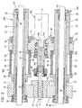
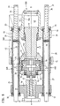
- Fig. 1 shows a purely hydraulic injection molding unit.
- This injection molding unit is partially enlarged shown in section in Fig. 2.
- the fifth drive group 500 serves as an injection means an injection cylinder 60 with cylinder space 61 and 62.
- This injection cylinder is closed by cylinder covers 63 and 64, which on the cylinder 27 of a nozzle driving unit the fourth drive group 400 slide.
- Hydraulic medium or pneumatic becomes the injection bridge 14 'along the spray axis s-s moves, with this movement, the conveyor 12 in the plasticizing cylinder 11 moves axially becomes.
- the plasticizing cylinder 11 is detachably attached to the support block 10, on which the Cylinder 27 is fixed.
- the cylinder 27 is coaxially penetrated by spars 31, which at the same time carry the piston 30 for the fourth drive group 400 of the jet travel drives.
- spars 31 which at the same time carry the piston 30 for the fourth drive group 400 of the jet travel drives.
- the injection bridge 14 ' carries in the middle a rotation transmission element 46, which together formed with the injection bridge 14 'as a multifunction element for the third drive group 300 is.
- the rotation transmission element 46 serves to transmit the rotation of a Metering drive 41, which is used to process the material to be processed and for this purpose the conveyor designed as a screw conveyor rotates the rotation transmission element 46 is located in a recess 14a 'of the injection bridge 14' and is there via the bearing 15 rotatably mounted and also fixed in the axial direction.
- the rotation transmission element 46 here has a recess 46a on the back, into which the drive shaft 41a of the metering drive 41 engages for operative connection.
- the dosing drive is a hydraulic rotary motor in Fig. 2, instead an electrically operated one High torque motor as in Fig. 3 are used. In this respect, both engines attack the same recess 46a, which can be clearly seen in FIG. 1.
- the structure of the transmission and metering motor 41 'of the third drive group 300 results from 5 to 7.
- the pinion 72 is mounted with the axis 72a in the gear housing and has a smaller pinion 72b on the same axis, which meshes with the pinion 71.
- the pinion 71 is mounted in the gear housing 47 with its axis 71a.
- the Pinion 71 meshes with pinion 70, which according to FIG. 5 with the rotation transmission element 46 is connected.
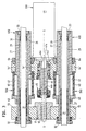
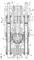
- FIG. 8 Another embodiment of the metering drive and above all the injection means 43 show Figures 8 to 10.
- the injection bridge 14 as a multifunction element for the fifth Assembly 500 is provided and has a contact surface 14a.
- This contact surface can 8 a pressure transmission element designed as an injection means 43 as a system serve.
- the pressure transmission element is supported on a support 18.
- Fig. 8 is the support 18 at one end of the cylinder 27 while the support block is arranged at the other end of the cylinder 27, so that over the cylinder 27th forms a force frame over which the injection means 43 is supported.
- a hydraulic or pneumatic piston 49 is provided as the injection means 43.
- This piston is guided in a pot-like recess 18a of the support 18.
- An electric motor is used as the metering drive 41 ' provided that drives the further drive element 20 via a gearbox, the Bearing 15 is mounted in the injection bridge.
- a first drive element is located in the injection bridge 14 19 provided, which is in the function here. It can be seen that the cylinder 27 serves only the injection bridge 14 and the support 18 as a guide, without further Cylinder, as interposed in Figs. 1 to 7.
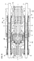
- Fig. 9 differs from Fig. 8 in that the injection means 43 is an electromechanical Drive 16 is provided, as it is from the older German patent application 197 31st 833.9 is known.
- the pot-like recess 18a of the support 18 supports part of the electromechanical spindle drive. The one interacting with this non-rotatable part rotatable part of this drive is mounted on the injection bridge 14.
- In the pot-like A threaded tube 16b comes to lie in the recess, which cooperates with a spindle head 16c, the spindle head 16c being arranged at the end of a linear movement means 16a is.
- This linear movement means 16a penetrates the pressure tube 26 Pressure transmission element coaxial and is driven by the first drive element 19, wherein the drive takes place via an electric motor of the fifth drive group 500.
- the pressure pipe 26, the is fixed in the recess 14a of the injection bridge, dips into the threaded tube in any position 16b, so that there is the impression of a piston-cylinder unit. This helps to protect the drive unit from dirt and enables insertion permanent lubrication.
- Threaded tube 16b and spindle head are connected to each other via planet 16d in connection.
- Pressure tube 26 and threaded tube 16b are indirect via an axial bearing element 40 connected.
- the forces occurring during injection are not via the linear movement means 16a to the drive element 19, but from the threaded tube 16b are transmitted to the spindle head 16c via the planets 16d.
- the spindle head passes these forces on the thrust bearing element 40, so that the pressure pipe to Pressure transmission element is.
- Via injection bridge 14, bearing element 17 and first drive element 19 the power flow continues via the axial bearing element 21 to the other Drive element 20 and the conveying means 12. Therefore, the linear movement means 16a only have to be dimensioned to the rotational forces and no longer to the pressure transmission.
- Fig. 10 differs from Fig. 9 in that the cylinder 27 is the primary element of a Linear motor is.
- a secondary element is arranged on the Hotm 31 as the nozzle travel drive 42.
- a relative movement takes place by appropriately loading the primary element of the primary element to the secondary element and thus the nozzle movement.
- Fig. 2,9 and 10 makes it clear that for different types of drive if the cylinder covers 32, 33 remain the same, only the cylinder is replaced accordingly must become. Is the different volumes of the hydraulic spaces 61, 62 in FIG. 2 waived and the cylinder would be prepared for this, possibly as the primary element of a linear motor To be used is basically no longer an exchange of the cylinder 27 required.
- the cylinder 27 serves as the cylinder cover 32, 33 as Multifunctional element for the fourth assembly 400, which is either inside as a cylinder for a hydraulic ring piston 30 or as a wall for the secondary element 75 of the linear motor serves.
- the cylinder can be used as a multifunction element for the fifth Module 500 be designed and serves the injection bridge 14, 14 'as a guide or optionally the piston rod of a hydraulic injection means 43.
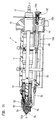
- FIGS 11, 12 show different embodiments of a plasticizing unit with a closure nozzle.
- the plasticizing unit P has a plasticizing cylinder 11 in which the conveying means 12 is included.
- the plasticizing unit is detachably attached to the carrier block 10, wherein when detaching the drive mechanism for the closure nozzle on the plasticizing cylinder remains.
- the nozzle needle 51 via a linkage 50 and a pivot lever 55 controlled.
- the nozzle body 52 is connected to the plasticizing cylinder via a connecting sleeve 53 11 connected.
- a nozzle insert 54 is arranged in the nozzle body 52.
- the linkage 50 ends in one Connection point 50a, with which it can be fixed to a hydraulic piston-cylinder unit is.
- a housing wall 80 is provided, which is connected to the plasticizing cylinder 11 is changed.
- the rod 50 penetrates this housing wall 80.
- this housing wall is e.g. used as the housing of a hollow shaft motor, the The linkage 50 'is actuated electromechanically via a roller screw drive 84.
- the linkage 50 ' is replaced by linkage 50.
- a comparison of the two representations shows that all elements for connecting the hollow shaft motor or another electrical Motors are provided so that only linkage and drive group are replaced must, e.g. to achieve a switch to clean room conditions at the customer.
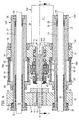
- the movable mold carrier 13 is a multifunctional element trained for the first and second drive group 100,200.
- the mold clamping unit is supported by bearing elements 88 on the machine base 35.
- the locking mechanism C is connected to the stationary mold carrier 34.
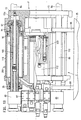
- the Closing mechanism C moves the movable mold carrier 13, which in the exemplary embodiments with a first support element 25 either via a threaded tube 89 or the cylinder 110 connected to an elongated movement unit in the form of a force frame is. Hydraulic drive groups are controlled from a hydraulic block 87. In the fully hydraulic configuration according to FIG. 13, the movable mold carrier 13 has a recess 13a.
- the piston rod 111 is the first Assembled assembly 100 for moving the movable mold carrier 13 until the positive connection.
- the recess 13a is in this case part of a pressure chamber within the cylinder 110.
- the first drive group 100 is also the piston rod 111 of the device for applying the closing force of the second drive group 200. It carries the piston 90, of the overflow channels, which are closed by a valve piston 91, the Movement is limited by a limiting element 92.
- the drive groups are electromechanical. Still, the hydraulic block 87, the further support element 85, the guide bars 86 and above all the movable Maintain mold carrier 13. While in Fig. 13 the cylinder 110 of the second assembly 200 for applying the closing force on the edge of the recess 13a is used in FIG 14 shows the recess 13a with a contact surface 13b with a threaded pipe 89 as a contact. This threaded tube is connected to planet 96, which is driven by a spindle head 95 are. The drive takes place via a drive rod 94 which is in a pressure pipe 93 rotates freely. Externally, there appears to be a piston-cylinder unit even when moving. The closing force can be shown in a manner not shown in the drawing, e.g. by a short-stroke cylinder can be applied, which acts on the further support element 85.
- FIG. 13 show the sixth drive group 600 of the ejector unit 24.
- two hydraulic piston-cylinder units are arranged around a compensating cylinder 112, which act on the ejector unit 24, which can also be designed as a core pull can.
- electromechanical spindle drives or e.g. the surface of the compensating cylinder 112 is also used as the primary element of a linear motor are, one connected to the ejector 24 in a manner not shown in the drawing Sleeve can be the secondary element.
- the ejector unit 24 can also move directly according to FIG. 14 Mold carrier 13 can be arranged.
- the ejector unit 24 is an independent structural one Designed unit, as is known from WO-A 97/12741, the disclosure content hereby expressly to the subject of the present application is made.
- the drive is a hollow shaft motor that contains the actuating element takes up, this ejector unit by appropriate rotation transmission elements can be used as unscrewing device or core pull. Instead of one Any other ejector can also be used, if ensured is that a connection to the movable mold carrier 13 is possible.
- the structure corresponds to that Structure in the earlier patent application 197 50 057.9.
- the locking mechanism C drives via a belt drive 81 to the drive rod 94.
- the drive rod 94 ends at the spindle head 95, which is connected to a threaded tube 89 via planet 96.
- the threaded pipe 89 is closed on the end face by a closure element 97, so that also here the impression of a piston-cylinder unit results, since the threaded elements externally are invisible.
- the movable mold carrier is divided into two parts 13 ', 13 "in order to to be able to take up the belt drive 81.
- the first drive group 100 does that Injection mold M up to positive locking.
- the first drive group 100 comes with its rotatable element 94 while reducing the Distance a in plant. This can happen at any time during the movement by that the switching chamber 98 is pressurized so that the further support element 85, which is a piston here, presses the bearing sleeve 83 to the left in FIG. 15.
- the first drive group 100 becomes the movable mold carrier 13 ', 13 "up to any one Gap between the mold halves or moved to the form fit, at the latest when the two halves of the casting mold are in contact with one another, a force and thus a deformation adjusts as a function of the force ratio between the switching chamber 98 and the pressure chamber 99 to reduce the distance a to earlier or later System of the pressure pipe 93 leads to the spindle head 95.
- This system prevents another Rotation.
- the pressure chamber 99 is activated at any point, so that, regardless of whether a positive connection has already been achieved or not, the switching chamber 98 is actively or passively relieved.
- the pressure pipe 93 is with the other designed as a piston Support element 85 connected. The position of the pressure pipe is due to the pressure in the Switching chamber 98 can be influenced.
- the further structure and operation of this Please refer to the older German patent application mentioned above.
Landscapes
- Engineering & Computer Science (AREA)
- Manufacturing & Machinery (AREA)
- Mechanical Engineering (AREA)
- Injection Moulding Of Plastics Or The Like (AREA)
- Moulds For Moulding Plastics Or The Like (AREA)
Description
- Fig. 1
- Eine dreidimensionale Ansicht der Spritzgießeinheit mit Blick auf die Einspritzbrükke, wobei sämtliche Antriebsgruppen hydraulisch betrieben sind,
- Fig. 2
- einen Schnitt durch die Spritzgießeinheit gemäß Fig. 1,
- Fig. 3
- einen Schnitt gemäß Fig. 2, wobei der Dosierantrieb über ein Hochmomentmotor elektrisch erfolgt,
- Fig. 4
- einen Schnitt gemäß Fig. 2, wobei das Fördermittel über ein Getriebe mit Servomotor gedreht wird,
- Fig. 5
- einen Schnitt nach Linie 5-5 von Fig. 4,
- Fig. 6
- einen Schnitt durch die Spritzgießeinheit im Bereich des Getriebes nach Linie 6-6 von Fig. 5,
- Fig. 7
- eine dreidimensionale Ansicht von Einspritzbrücke und Getriebe,
- Fig. 8
- einen Schnitt gemäß Fig. 2 mit einer veränderten Einspritzbrücke und hydraulischem Einspritzen,
- Fig. 9
- einen Schnitt gemäß Fig. 8 mit einer elektromechanischen Einspritzeinheit,
- Fig. 10
- einen Schnitt gemäß Fig. 8, wobei der Düsenfahrantrieb ein Linearmotor ist,
- Fig. 11
- eine teilweise geschnittene Seitenansicht eines am Trägerblock befestigten Plastifizierzylinders mit einem hydraulischen Antrieb für eine Verschlußdüse,
- Fig. 12
- eine Darstellung gemäß Fig. 11 mit einem elektromechanischen Antrieb für die Verschlußdüse,
- Fig. 13
- eine teilweise geschnittene Seitenansicht einer hydraulisch betriebenen Formschließeinheit,
- Fig. 14
- eine Darstellung gemäß Fig. 13, wobei alle Antriebe elektromechanisch erfolgen,
- Fig. 15
- eine Seitenansicht einer Formschließeinheit mit elektromechanischem Schließmechanismus und hydraulischer Aufbringung der Schließkraft,
- Fig. 16
- eine isometrische Darstellung der Spritzgießmaschine mit den Arbeitsgruppen.
- hydraulisch mit Ölmotor (radial, axial, Zahnrad, Drehmoment)
- elektrisch mit konstantem Motor oder Regetmotor und Getriebe
- hydraulisch mit Zylinder
- elektrisch mit Umsetzung Rotation in Translation
- pneumatisch mit Zylinder
- elektrisch mit Linearmotor
- hydraulisch mit Zylinder
- elektrisch mit Umsetzung Rotation in Translation
- pneumatisch mit Zylinder
- elektrisch mit Linearmotor
- hydraulisch mit Zylinder
- pneumatisch mit Zylinder
- Elektromagnet
- Elektromotor Rotation in Translation
- elektrisch über Linearmotor
- hydraulisch mit Zylinder über Kniehebel oder unmittelbar
- elektrisch mit Umsetzung Rotation in Translation
- Linearmotor
- hydraulisch mit Zylinder über Kniehebel oder unmittelbar
- elektrisch mit Kniehebel oder Exzenter
- hydraulisch mit Zylinder
- pneumatisch mit Zylinder
- elektrisch mit Umsetzung Rotation in Translation
- elektrischer Linearmotor
- 10
- Trägerblock
- 11
- Plastifizierzylinder
- 12
- Fördermittel
- 13,13',13
- " beweglicher Formträger
- 13a
- Ausnehmung
- 13b
- Anlagefläche
- 14,14'
- Einspritzbrücke
- 14a
- Anlagefläche'
- 14a'
- Ausnehmung
- 15
- Lagerelement für 46
- 16
- elektromechanischer Antrieb
- 16a
- Linearbewegungsmittel
- 16b
- Gewinderohr
- 16c
- Spindelkopf
- 16d
- Planeten
- 17
- Lagerelement für 16a
- 18
- Abstützung
- 18a
- topfartige Ausnehmung
- 19
- erstes Antriebselement von 500
- 20
- weiteres Antriebselement von 41
- 21,40
- Axial-Lagerelement
- 22
- Gehäusedeckel
- 24
- Auswerfereinheit
- 25
- erstes Abstützelement
- 26
- Druckübertragungselement
- 27
- Zylinder
- 28,29
- Zylinderkammer
- 30
- Ringkolben
- 31
- Holm
- 32,33
- Zylinderdeckel
- 34
- stationärer Formträger
- 83
- Lagerhülse
- 84
- Wälzgewindeantrieb
- 85
- weiteres Abstützelement
- 86
- Führungsholm
- 87
- Hydraulikblock
- 88
- Lagerelement
- 89
- Gewinderohr (Fig. 14)
- 90
- Kolben (Fig. 13)
- 91
- Ventilkolben
- 92
- Begrenzungselement
- 93
- Druckrohr
- 94
- Antriebsstange
- 95
- Spindelkopf
- 96
- Planeten
- 97
- Verschlußelement
- 98
- Schaltkammer
- 99
- Druckkammer
- 100
- erste Antriebsgruppe
- 110
- Zylinder
- 111
- Kolbenstange
- 112
- Ausgleichszylinder
- 35
- Maschinenfuß
- 36
- Bohrung
- 41,41',41
- " Dosierantrieb
- 41a,41a'
- Antriebswelle
- 42
- Düsenfahrantrieb
- 43
- Einspritzmittel
- 45
- Verriegelungsmechanismus
- 46
- Rotationsübertragungselement
- 46a
- Ausnehmung
- 46b
- Abschnitt
- 47
- Getriebegehäuse
- 48
- Zylinderraum (Fig. 8)
- 49
- Kolben
- 50,50'
- Gestänge für 51
- 50a
- Anschlußpunkt
- 51
- Düsennadel
- 52
- Düsenkörper
- 52a
- Düsenmündung
- 53
- Verbindungsmuffe
- 54
- Düseneinsatz
- 55
- Schwenkhebel
- 60
- Zylinder
- 61,62
- Zylinderkammer
- 63,64
- Zylinderdeckel
- 70,71,72
- Ritzel
- 71a,72a
- Achse
- 72b
- Ritzel
- 75
- Sekundärelement
- 80
- Gehäusewandung
- 81
- Riementrieb
- 82
- Kolben-Zylinder-Einheit
- 200-700
- zweite bis siebte Antriebsgruppe
- a
- Abstand
- a-a
- Wirkachse
- s-s
- Spritzachse
- C
- Schließmechanismus
- F
- Formschließeinheit
- M
- Spritzgießwerkzeug
- P
- Plastifiziereinheit
- R
- Formspannraum
- S
- Spritzgießeinheit
- MF
- Multifunktionselement
Claims (19)
- Spritzgießmaschine zur Verarbeitung von Kunststoffen und anderer plastifizierbarer Materialien mit einem mehrere Antriebsgruppen umfassenden modularen Aufbau, mitdadurch gekennzeichnet, daß wenigstens eine der Antriebsgruppen (100, 300, 400, 500) über wenigstens ein Multifunktionselement mit der Spritzgießmaschine verbindbar ist, das als Schnittstelle wahlweise dem Anschluß von wenigstens zwei verschiedenartigen Antriebsarten aus der Gruppe der elektromechanischen Antriebe, der hydraulischen Antriebe, der pneumatischen Antriebe, der Linearmotoren oder der elektromagnetischen Antriebe als Antriebsgruppe bei ansonsten unveränderter Spritzgießmaschine dient, wobei für die Antriebsgruppen (100, 300, 400, 500) unabhängig vom jeweiligen Antrieb Raum an der Spritzgießmaschine zur Unterbringung jeder Antriebsart zur Verfügung gestellt ist.einem Maschinenfuß (35),einer Formschließeinheit (F) miteinem mit dem Maschinenfuß (35) verbundenen stationären Formträger (34),einem beweglichen Formträger (13), der zwischen sich und dem stationären Formträger (34) einen Formspannraum (R) ausbildet,wenigstens einem Spritzgießwerkzeug (M), dessen Formteile im Formspannraum (R) am stationären Formträger (34) und am beweglichen Formträger (13) aufnehmbar sind,einem Schließmechanismus (C) als erste Antriebsgruppe (100) zum Bewegen des beweglichen Formträgers (13) auf den stationären Formträger (34) zu und von diesem weg unter Schließen des Spritzgießwerkzeuges (M),Kraftübertragungsmitteln zum Übertragen im wesentlichen der Schließkraft vom Schließmechanismus (C) auf den stationären Formträger (34),einer Spritzgießeinheit (S) miteiner Plastifiziereinheit (P), die einen Plastifizierzylinder (11) und ein im Plastifizierzylinder aufgenommenes Fördermittel (12) sowie stirnseitig eine in einer Spritzachse (s-s) liegende Düsenmündung (52a) aufweist,einem auf dem Maschinenfuß (35) entlang der Spritzachse (s-s) beweglich angeordneten Trägerblock (10), an dem die Plastifiziereinheit (P) lösbar befestigt ist,einer Einspritzbrücke (14),einem Dosierantrieb (41,41') für das Fördermittel (12) der Plastifiziereinheit (P) als dritte Antriebsgruppe (300), die mit der Einspritzbrücke (14) verbindbar ist,wenigstens einem, zur Spritzachse (s-s) parallelachsigen, Düsenfahrantrieb (42) als vierte Antriebsgruppe (400) zum Bewegen der Düsenmündung (52a) auf das Spritzgießwerkzeug (M) zu und von diesem weg,wenigstens einem zur Spritzachse (s-s) parallelachsigen Einspritzmittel (43) als fünfte Antriebsgruppe (500) zur Relativbewegung des Fördermittels (12) gegenüber dem Plastifizierzylinder (11),
- Spritzgießmaschine nach Anspruch 1, dadurch gekennzeichnet, daß der Schließmechanismus ein erstes Abstützelement (25) zur Abstützung aufweist und daß als zweite Antriebsgruppe (200) eine ebenfalls über ein Multifunktionselement mit der Spritzgießmaschine verbindbare Einrichtung zur Aufbringung der Schließkraft vorgesehen ist, sobald die erste Antriebsgruppe (100) den beweglichen Formträger bis zum Schließen der Spritzgießform (M) überführt hat.
- Spritzgießmaschine nach Anspruch 1 oder 2, dadurch gekennzeichnet, daß als sechste Antriebsgruppe (600) eine Auswerfereinheit (24) vorgesehen ist, die ebenfalls über ein Multifunktionselement mit einem der Formträger (11,12) verbindbar ist.
- Spritzgießmaschine nach Anspruch 3, dadurch gekennzeichnet, daß an dem Multifunktionselement, an dem die Auswerfereinheit (24) angeschlossen ist, auch der Auswerfer (24) als Kernzug anschließbar ist.
- Spritzgießmaschine nach einem der Ansprüche 1 bis 4, dadurch gekennzeichnet, daß als siebte Antriebsgruppe (700) ein Antrieb für die Düsennadel (51) eines verschließbaren Düsenkörpers (52) vorgesehen ist, der ebenfalls über ein Multifunktionselement mit der Spritzgießmaschine verbindbar ist.
- Spritzgießmaschine nach einem der vorhergehenden Ansprüche, dadurch gekennzeichnet, daß auf der Seite der Spritzgießeinheit die Einspritzbrücke (14') und ein darin drehbar gelagertes Rotationsübertragungselement (46) zur Übertragung der Rotation eines Dosierantriebs (41,41') für die dritte Antriebsgruppe (300) als Multifunktionselemente ausgebildet sind.
- Spritzgießmaschine nach Anspruch 6, dadurch gekennzeichnet, daß das Rotationsübertragungselement (46) eine Ausnehmung (46a) aufweist, in das der Antriebsschaft (41a) des Dosierantriebs (41) zur Wirkverbindung eingreift, wobei der Dosierantrieb (41) ein hydraulischer Rotationsmotor oder ein elektrisch betriebener Hochmomentmotor ist.
- Spritzgießmaschine nach Anspruch 6 oder 7, dadurch gekennzeichnet, daß das Rotationsübertragungselement (46) mit einem Abschnitt (46b) aus der Einspritzbrücke (14') herausragt, an dem ein Getriebegehäuse (47) mit zugehörigem Getriebe ankoppelbar ist, das von einem Dosierantrieb (41') angetrieben ist.
- Spritzgießmaschine nach einem der Ansprüche 1 bis 5, dadurch gekennzeichnet, daß die Einspritzbrücke (14) als Multifunktionselement für die fünfte Antriebsgruppe (500) eine Anlagefläche (14a) aufweist, die einem als Einspritzmittel (43) ausgebildeten Druckübertragungselement als Anlage dient, das sich an einer mit der Einspritzbrücke (14) in Verbindung stehenden Abstützung (18) abstützt und vorzugsweise hydraulisch oder elektromechanisch als Einspritzmittel (43) bewegbar ist.
- Spritzgießmaschine nach Anspruch 9, dadurch gekennzeichnet, daß die Abstützung (18) eine topfartige Ausnehmung (18a) aufweist, die entweder einen Zylinderraum (48) für das als Kolben (49) ausgebildete Einspritzmittel (43) bildet oder einen drehfesten Teil eines elektromechanischen Spindelantriebs aufnimmt, der mit einem an der Einspritzbrücke (14) gelagerten drehbaren Teil zusammenwirkt.
- Spritzgießmaschine nach Anspruch 9 oder 10, dadurch gekennzeichnet, daß in einer topfartigen Ausnehmung (18a) der Abstützung (18) ein Gewinderohr (16b) drehfest aufgenommen ist, das mit einem Spindelkopf (16c) zusammenwirkt, wobei der Spindelkopf (16c) am Ende eines Linearbewegungsmittels (16a) angeordnet ist, das das als Rohr (26) ausgebildete Druckübertragungselement zentral durchdringt und das über ein in der Einspritzbrücke (14) angeordnetes erstes Antriebselement (19) drehbar ist.
- Spritzgießmaschine nach einem der vorhergehenden Ansprüche, dadurch gekennzeichnet, daß in der Einspritzbrücke (14) ein zu einem ersten Antriebselement (19) für das Einspritzmittel (43) koaxiales Antriebselement (20) zur Rotation des Fördermittels angeordnet ist.
- Spritzgießmaschine nach Anspruch 11 oder 12, dadurch gekennzeichnet, daß zwischen erstem Antriebselement (19) und weiterem Antriebselement (20) ein Axiallagerelement (21) vorgesehen ist, das einerseits als Kraftübertragungsetement und andererseits als Trennmittel zwischen den Antriebselementen (19,20) dient.
- Spritzgießmaschine nach einem der vorhergehenden Ansprüche, dadurch gekennzeichnet, daß die auf den als Kraftübertragungsmitteln ausgebildeten Führungsholmen (31) angeordneten Zylinderdeckel (32,33) als Multifunktionselement für die vierte Antriebsgruppe (400) ausgebildet sind, die zwischen sich den Zylinder (27) aufnehmen, der entweder als Zylinder für einen hydraulischen Ringkolben (30) oder als Wandung für ein Sekundärelement (75) eines Linearmotors ausgebildet ist.
- Spritzgießmaschine nach einem der vorhergehenden Ansprüche, dadurch gekennzeichnet, daß ein Zylinder (27) der vierten Antriebsgruppe (400) außenseitig als Multifunktionselement für die fünfte Antriebsgruppe (500) ausgebildet ist und der Einspritzbrücke (14,14') als Führung dient.
- Spritzgießmaschine nach Anspruch 15, dadurch gekennzeichnet, daß der Zylinder (27) die Kolbenstange für ein hydraulisches Einspritzmittel (43) ist.
- Spritzgießmaschine nach Anspruch 5, dadurch gekennzeichnet, daß am Trägerblock (10) als Multifunktionselement zur Anbringung der siebten Antriebsgruppe (700) zur Betätigung der Düsennadel (51) eine Gehäusewandung (80) befestigt ist, die entweder vom Gestänge (50) zur Betätigung der Düsennadel (51) durchdrungen ist, wenn eine hydraulische Betätigung erfolgt, oder mit einem anderen Gestänge (50') über einen Wälzgewindeantrieb (84) in wirkverbindung steht, dem die Gehäusewandung (80) als Gehäuse dient.
- Spritzgießmaschine nach einem der vorhergehenden Ansprüche, dadurch gekennzeichnet. daß der bewegliche Formträger (13) als Multifunktionselement für die erste und zweite Antriebsgruppe (100,200) eine Ausnehmung (13a) aufweist, an deren Boden sich entweder ein Gewinderohr (89) eines elektromechanischen Antriebs abstützt oder die einen Teil eines hydraulischen Kolbens (90) aufnimmt, dessen Zylinder (110) am Rand der Ausnehmung (13a) festgelegt ist.
- Spritzgießmaschine nach einem der Ansprüche 2 bis 17, dadurch gekennzeichnet, daß zwischen erstem Abstützelement (25) und beweglichem Formträger (13;13',13 " ) als Multifunktionselement ein weiteres Abstützelement (85) angeordnet ist, das über eine mit Hydraulikmedium beaufschlagbare Schaltkammer (98) beaufschlagbar ist, wobei die Schaltkammer (98), wenn sie unter Druck steht, die Bewegung der ersten Antriebsgruppe (100) erlaubt, während die Schaltkammer (98) die Bewegung der ersten Antriebsgruppe (100) blockiert, wenn die Schaltkammer (98) druckfrei ist, wobei der Druck des Hydraulikmediums in der Schaltkammer (98) ebenso zuschaltbar ist wie die zweite Antriebsgruppe (200).
Applications Claiming Priority (3)
| Application Number | Priority Date | Filing Date | Title |
|---|---|---|---|
| DE19847298 | 1998-10-14 | ||
| DE19847298A DE19847298C2 (de) | 1998-10-14 | 1998-10-14 | Spritzgießmaschine mit einem mehrere Antriebsgruppen umfassenden modularen Aufbau |
| PCT/EP1999/007582 WO2000021729A1 (de) | 1998-10-14 | 1999-10-09 | Spritzgiessmaschine mit einem mehrere antriebsgruppen umfassenden modularen aufbau |
Publications (3)
| Publication Number | Publication Date |
|---|---|
| EP1121237A1 EP1121237A1 (de) | 2001-08-08 |
| EP1121237B1 true EP1121237B1 (de) | 2002-12-11 |
| EP1121237B2 EP1121237B2 (de) | 2010-08-04 |
Family
ID=7884405
Family Applications (1)
| Application Number | Title | Priority Date | Filing Date |
|---|---|---|---|
| EP99952546A Expired - Lifetime EP1121237B2 (de) | 1998-10-14 | 1999-10-09 | Spritzgiessmaschine mit einem mehrere antriebsgruppen umfassenden modularen aufbau |
Country Status (7)
| Country | Link |
|---|---|
| US (1) | US6517337B1 (de) |
| EP (1) | EP1121237B2 (de) |
| JP (1) | JP2002527256A (de) |
| AT (1) | ATE229422T1 (de) |
| CA (1) | CA2347458C (de) |
| DE (2) | DE19847298C2 (de) |
| WO (1) | WO2000021729A1 (de) |
Cited By (1)
| Publication number | Priority date | Publication date | Assignee | Title |
|---|---|---|---|---|
| DE10309906B3 (de) * | 2003-02-25 | 2004-06-09 | Karl Hehl | Formschließeinheit für eine Spritzgießmaschine zur Verarbeitung von Kunststoffen |
Families Citing this family (22)
| Publication number | Priority date | Publication date | Assignee | Title |
|---|---|---|---|---|
| DE10022192A1 (de) * | 2000-05-03 | 2001-11-15 | Mannesmann Ag | Einrichtung zum Entfernen von Spritzgießteilen |
| DE50201729D1 (de) * | 2001-02-15 | 2005-01-13 | Mannesmann Plastics Machinery | Schliesseinrichtung in einer spritzgiessmaschine für kunststoffe |
| AT5362U1 (de) | 2001-05-11 | 2002-06-25 | Engel Gmbh Maschbau | Einrichtung zum spritzgiessen von kunststoff |
| CN100457419C (zh) | 2002-10-31 | 2009-02-04 | 住友重机械工业株式会社 | 成形机及其控制方法 |
| DE102004033690A1 (de) * | 2004-07-09 | 2006-02-16 | Demag Ergotech Gmbh | Spritzgiessmaschine |
| DE102004057164A1 (de) * | 2004-11-26 | 2006-06-01 | Krauss-Maffei Kunststofftechnik Gmbh | Spritzgießmaschine |
| DE202005021060U1 (de) * | 2005-09-14 | 2007-01-18 | Siemens Ag | Spritzgießmaschine |
| USD559285S1 (en) * | 2005-10-03 | 2008-01-08 | Galomb David E | Injection molding machine |
| US7772266B2 (en) | 2006-02-15 | 2010-08-10 | Dendreon Corporation | Small-molecule modulators of TRP-P8 activity |
| US20070296121A1 (en) * | 2006-06-07 | 2007-12-27 | Husky Injection Molding Systems Ltd. | Molding-system drive |
| US20070296281A1 (en) * | 2006-06-07 | 2007-12-27 | Husky Injection Molding Systems Ltd. | Electrical motor |
| US7695266B2 (en) * | 2006-11-02 | 2010-04-13 | Husky Injection Molding Systems Ltd. | Molding structure |
| DE102007042643A1 (de) | 2007-09-07 | 2009-04-02 | Siemens Ag | Verfahren zum Betrieb einer Einspritzeinrichtung für eine Spritzgießmaschine, Einspritzeinrichtung sowie Spritzgießmaschine mit einer derartigen Einspritzeinrichtung |
| GB2478732B (en) | 2010-03-15 | 2014-08-20 | Kraft Foods R & D Inc | Improvements in injection moulding |
| CN102211383B (zh) * | 2010-04-01 | 2013-11-06 | 永高股份有限公司 | 塑料模具二次滑块抽芯机构 |
| DE102010046275A1 (de) * | 2010-09-22 | 2012-03-22 | Netstal-Maschinen Ag | Universelle Hilfssteuerung für eine Spritzgießmaschine |
| JP5980865B2 (ja) * | 2014-09-11 | 2016-08-31 | ファナック株式会社 | 射出成形機 |
| DE102016205554B4 (de) * | 2016-04-04 | 2022-02-24 | Rekers Gmbh Maschinen- Und Anlagenbau | Ziehdornvorrichtung für eine Steinformmaschine, Steinformmaschine und Verfahren zur Herstellung von Formsteinen |
| JP6867978B2 (ja) * | 2018-06-13 | 2021-05-12 | 日精樹脂工業株式会社 | 射出成形機及びその成形方法 |
| JP7605574B2 (ja) * | 2021-06-14 | 2024-12-24 | 株式会社日本製鋼所 | 射出装置および射出成形機 |
| DE102024131208A1 (de) | 2024-10-25 | 2026-04-30 | Arburg Gmbh + Co Kg | Maschine zur Verarbeitung von Kunststoffen mit modularem Aufbau |
| DE102024131207B3 (de) * | 2024-10-25 | 2025-11-27 | Arburg Gmbh + Co Kg | Spritzgießeinheit zur Verarbeitung von Kunststoffen, damit versehene Spritzgießmaschine sowie zugehöriger Bausatz |
Family Cites Families (6)
| Publication number | Priority date | Publication date | Assignee | Title |
|---|---|---|---|---|
| DE2247386A1 (de) † | 1972-09-27 | 1974-03-28 | Demag Ag | Vorrichtung fuer den antrieb der schnecke einer schneckenspritzgiessmaschine |
| EP0576925B1 (de) * | 1992-06-23 | 1997-08-20 | Battenfeld Kunststoffmaschinen Ges.m.b.H. | Spritzaggregat für Spritzgiessmaschinen |
| DE19536565C2 (de) | 1995-10-02 | 1998-07-16 | Karl Hehl | Spritzgießmaschine zur Verarbeitung plastifizierbarer Massen |
| DE19536567C2 (de) | 1995-10-02 | 1998-12-17 | Karl Hehl | Formschließeinheit mit einer Einrichtung zur Behandlung und/oder Entfernung von Spritzteilen |
| DE19731833C1 (de) * | 1997-07-24 | 1999-01-14 | Karl Hehl | Spritzgießeinheit für eine Spritzgießmaschine |
| DE19750057C2 (de) | 1997-11-12 | 2000-08-03 | Karl Hehl | Formschließeinheit für eine Spritzgießmaschine |
-
1998
- 1998-10-14 DE DE19847298A patent/DE19847298C2/de not_active Expired - Fee Related
-
1999
- 1999-10-09 WO PCT/EP1999/007582 patent/WO2000021729A1/de not_active Ceased
- 1999-10-09 DE DE59903783T patent/DE59903783D1/de not_active Expired - Lifetime
- 1999-10-09 JP JP2000575673A patent/JP2002527256A/ja active Pending
- 1999-10-09 AT AT99952546T patent/ATE229422T1/de active
- 1999-10-09 EP EP99952546A patent/EP1121237B2/de not_active Expired - Lifetime
- 1999-10-09 CA CA002347458A patent/CA2347458C/en not_active Expired - Fee Related
- 1999-10-09 US US09/807,395 patent/US6517337B1/en not_active Expired - Lifetime
Cited By (1)
| Publication number | Priority date | Publication date | Assignee | Title |
|---|---|---|---|---|
| DE10309906B3 (de) * | 2003-02-25 | 2004-06-09 | Karl Hehl | Formschließeinheit für eine Spritzgießmaschine zur Verarbeitung von Kunststoffen |
Also Published As
| Publication number | Publication date |
|---|---|
| EP1121237A1 (de) | 2001-08-08 |
| DE59903783D1 (de) | 2003-01-23 |
| DE19847298C2 (de) | 2000-11-02 |
| CA2347458A1 (en) | 2000-04-20 |
| EP1121237B2 (de) | 2010-08-04 |
| JP2002527256A (ja) | 2002-08-27 |
| US6517337B1 (en) | 2003-02-11 |
| CA2347458C (en) | 2008-11-25 |
| WO2000021729A1 (de) | 2000-04-20 |
| DE19847298A1 (de) | 2000-04-27 |
| ATE229422T1 (de) | 2002-12-15 |
Similar Documents
| Publication | Publication Date | Title |
|---|---|---|
| EP1121237B1 (de) | Spritzgiessmaschine mit einem mehrere antriebsgruppen umfassenden modularen aufbau | |
| EP2726267B1 (de) | Drehvorrichtung für eine spritzgiessvorrichtung | |
| DE2055261C3 (de) | Kunststoff-Spritzgießmaschine zum Herstellen von aus zwei verschiedenen Kunststoffmassen bestehenden Spritzgußteilen | |
| DE2113414A1 (de) | Schliess-,Verriegelungs- und Vorspann-Vorrichtung fuer Giessformen | |
| DE19920626C2 (de) | Spritzgießmaschine zur Verarbeitung von Kunststoffen | |
| EP0508277B1 (de) | Verschiebe- und/oder Stellkraft-Antriebsvorrichtung für Spritzgiessmaschinen | |
| EP1284849A1 (de) | Spritzeinheit für spritzgiessmaschinen mit kontinuierlich arbeitender plastifiziereinheit | |
| EP1097035B1 (de) | Spritzgiesseinheit für eine spritzgiessmaschine | |
| EP1339537B1 (de) | Einspritzeinheit für eine spritzgiessmaschine | |
| EP1768828B1 (de) | Spritzgiessmaschine | |
| EP3710222B1 (de) | Formschliesseinheit für eine spritzgiessmaschine sowie verfahren zum verriegeln eines kraftübertragungselements | |
| EP0576837B1 (de) | Spritzgiessmaschine mit Etagenwerkzeug | |
| AT525797B1 (de) | Kniehebel-Schließeinheit und Verfahren zum Formschließen und Formöffnen | |
| EP3672776B1 (de) | Formschliesseinheit für eine spritzgiessmaschine sowie verfahren zum verriegeln eines kraftübertragungselements | |
| EP0107778B1 (de) | Verfahren und Vorrichtung zur Verarbeitung einer plastifizierbaren Masse | |
| EP3959058B1 (de) | Spritzgiesseinheit für eine spritzgiessmaschine zur verarbeitung von kunststoffen | |
| EP0585671B1 (de) | Auswerfereinheit für Spritzgiessmaschinen | |
| EP1802441B1 (de) | Schliesseinheit für eine spritzgiessmaschine mit etagenwerkzeug | |
| DE60108432T2 (de) | Antriebsvorrichtung für Spritzgiessmaschine | |
| EP4458547A1 (de) | Formschliesseinheit und verfahren zum betreiben einer formschliesseinheit einer maschine zur verarbeitung von kunststoffen | |
| DE19605747C2 (de) | Antriebseinheit für Plastifizier- und Einspritzeinheiten von Kunststoff-Spritzgießmaschinen | |
| DE19535081C2 (de) | Zwei-Platten-Spritzgießmaschine | |
| EP2719517B1 (de) | Spritzgiessmaschine | |
| DE19712494C2 (de) | Kolben-Spritzvorrichtung mit Schneckenvorplastifizierung | |
| DE10040322B4 (de) | Kunststoffspritzgießmaschine und Antriebsvorrichtung für eine Kunststoffspritzgießmaschine |
Legal Events
| Date | Code | Title | Description |
|---|---|---|---|
| PUAI | Public reference made under article 153(3) epc to a published international application that has entered the european phase |
Free format text: ORIGINAL CODE: 0009012 |
|
| 17P | Request for examination filed |
Effective date: 20010320 |
|
| AK | Designated contracting states |
Kind code of ref document: A1 Designated state(s): AT BE CH CY DE DK ES FI FR GB GR IE IT LI LU MC NL PT SE |
|
| GRAG | Despatch of communication of intention to grant |
Free format text: ORIGINAL CODE: EPIDOS AGRA |
|
| 17Q | First examination report despatched |
Effective date: 20020102 |
|
| GRAG | Despatch of communication of intention to grant |
Free format text: ORIGINAL CODE: EPIDOS AGRA |
|
| GRAH | Despatch of communication of intention to grant a patent |
Free format text: ORIGINAL CODE: EPIDOS IGRA |
|
| GRAH | Despatch of communication of intention to grant a patent |
Free format text: ORIGINAL CODE: EPIDOS IGRA |
|
| GRAA | (expected) grant |
Free format text: ORIGINAL CODE: 0009210 |
|
| AK | Designated contracting states |
Kind code of ref document: B1 Designated state(s): AT CH DE FR GB IT LI |
|
| REF | Corresponds to: |
Ref document number: 229422 Country of ref document: AT Date of ref document: 20021215 Kind code of ref document: T |
|
| REG | Reference to a national code |
Ref country code: GB Ref legal event code: FG4D Free format text: NOT ENGLISH |
|
| REG | Reference to a national code |
Ref country code: CH Ref legal event code: EP |
|
| REG | Reference to a national code |
Ref country code: CH Ref legal event code: NV Representative=s name: LUCHS & PARTNER PATENTANWAELTE |
|
| REF | Corresponds to: |
Ref document number: 59903783 Country of ref document: DE Date of ref document: 20030123 |
|
| GBT | Gb: translation of ep patent filed (gb section 77(6)(a)/1977) |
Effective date: 20030307 |
|
| ET | Fr: translation filed | ||
| PLBQ | Unpublished change to opponent data |
Free format text: ORIGINAL CODE: EPIDOS OPPO |
|
| PLBI | Opposition filed |
Free format text: ORIGINAL CODE: 0009260 |
|
| 26 | Opposition filed |
Opponent name: ENGEL AUSTRIA GMBH Effective date: 20030905 |
|
| PLAX | Notice of opposition and request to file observation + time limit sent |
Free format text: ORIGINAL CODE: EPIDOSNOBS2 |
|
| PLAX | Notice of opposition and request to file observation + time limit sent |
Free format text: ORIGINAL CODE: EPIDOSNOBS2 |
|
| PLAX | Notice of opposition and request to file observation + time limit sent |
Free format text: ORIGINAL CODE: EPIDOSNOBS2 |
|
| PLBB | Reply of patent proprietor to notice(s) of opposition received |
Free format text: ORIGINAL CODE: EPIDOSNOBS3 |
|
| PLAY | Examination report in opposition despatched + time limit |
Free format text: ORIGINAL CODE: EPIDOSNORE2 |
|
| PLBC | Reply to examination report in opposition received |
Free format text: ORIGINAL CODE: EPIDOSNORE3 |
|
| PGFP | Annual fee paid to national office [announced via postgrant information from national office to epo] |
Ref country code: GB Payment date: 20061024 Year of fee payment: 8 |
|
| PLAB | Opposition data, opponent's data or that of the opponent's representative modified |
Free format text: ORIGINAL CODE: 0009299OPPO |
|
| R26 | Opposition filed (corrected) |
Opponent name: ENGEL AUSTRIA GMBH Effective date: 20030905 |
|
| APBP | Date of receipt of notice of appeal recorded |
Free format text: ORIGINAL CODE: EPIDOSNNOA2O |
|
| APAH | Appeal reference modified |
Free format text: ORIGINAL CODE: EPIDOSCREFNO |
|
| APBQ | Date of receipt of statement of grounds of appeal recorded |
Free format text: ORIGINAL CODE: EPIDOSNNOA3O |
|
| GBPC | Gb: european patent ceased through non-payment of renewal fee |
Effective date: 20071009 |
|
| PG25 | Lapsed in a contracting state [announced via postgrant information from national office to epo] |
Ref country code: GB Free format text: LAPSE BECAUSE OF NON-PAYMENT OF DUE FEES Effective date: 20071009 |
|
| APBU | Appeal procedure closed |
Free format text: ORIGINAL CODE: EPIDOSNNOA9O |
|
| PUAH | Patent maintained in amended form |
Free format text: ORIGINAL CODE: 0009272 |
|
| STAA | Information on the status of an ep patent application or granted ep patent |
Free format text: STATUS: PATENT MAINTAINED AS AMENDED |
|
| 27A | Patent maintained in amended form |
Effective date: 20100804 |
|
| AK | Designated contracting states |
Kind code of ref document: B2 Designated state(s): AT CH DE FR GB IT LI |
|
| REG | Reference to a national code |
Ref country code: CH Ref legal event code: AEN Free format text: AUFRECHTERHALTUNG DES PATENTES IN GEAENDERTER FORM |
|
| PGFP | Annual fee paid to national office [announced via postgrant information from national office to epo] |
Ref country code: FR Payment date: 20111103 Year of fee payment: 13 |
|
| REG | Reference to a national code |
Ref country code: FR Ref legal event code: ST Effective date: 20130628 |
|
| PG25 | Lapsed in a contracting state [announced via postgrant information from national office to epo] |
Ref country code: FR Free format text: LAPSE BECAUSE OF NON-PAYMENT OF DUE FEES Effective date: 20121031 |
|
| PGFP | Annual fee paid to national office [announced via postgrant information from national office to epo] |
Ref country code: IT Payment date: 20131030 Year of fee payment: 15 |
|
| REG | Reference to a national code |
Ref country code: DE Ref legal event code: R082 Ref document number: 59903783 Country of ref document: DE Representative=s name: PATENTANWAELTE REINHARDT & POHLMANN PARTNERSCH, DE |
|
| REG | Reference to a national code |
Ref country code: DE Ref legal event code: R082 Ref document number: 59903783 Country of ref document: DE Representative=s name: RPK PATENTANWAELTE REINHARDT, POHLMANN UND KAU, DE Effective date: 20140731 Ref country code: DE Ref legal event code: R082 Ref document number: 59903783 Country of ref document: DE Representative=s name: PATENTANWAELTE REINHARDT & POHLMANN PARTNERSCH, DE Effective date: 20140731 Ref country code: DE Ref legal event code: R081 Ref document number: 59903783 Country of ref document: DE Owner name: KEINATH, RENATE, DE Free format text: FORMER OWNER: HEHL, KARL, 72290 LOSSBURG, VERSTORBEN, DE Effective date: 20140731 |
|
| PG25 | Lapsed in a contracting state [announced via postgrant information from national office to epo] |
Ref country code: IT Free format text: LAPSE BECAUSE OF NON-PAYMENT OF DUE FEES Effective date: 20141009 |
|
| PGFP | Annual fee paid to national office [announced via postgrant information from national office to epo] |
Ref country code: CH Payment date: 20151026 Year of fee payment: 17 |
|
| PGFP | Annual fee paid to national office [announced via postgrant information from national office to epo] |
Ref country code: DE Payment date: 20160805 Year of fee payment: 18 |
|
| PGFP | Annual fee paid to national office [announced via postgrant information from national office to epo] |
Ref country code: AT Payment date: 20161024 Year of fee payment: 18 |
|
| REG | Reference to a national code |
Ref country code: CH Ref legal event code: PL |
|
| PG25 | Lapsed in a contracting state [announced via postgrant information from national office to epo] |
Ref country code: CH Free format text: LAPSE BECAUSE OF NON-PAYMENT OF DUE FEES Effective date: 20161031 Ref country code: LI Free format text: LAPSE BECAUSE OF NON-PAYMENT OF DUE FEES Effective date: 20161031 |
|
| REG | Reference to a national code |
Ref country code: DE Ref legal event code: R119 Ref document number: 59903783 Country of ref document: DE |
|
| REG | Reference to a national code |
Ref country code: AT Ref legal event code: MM01 Ref document number: 229422 Country of ref document: AT Kind code of ref document: T Effective date: 20171009 |
|
| PG25 | Lapsed in a contracting state [announced via postgrant information from national office to epo] |
Ref country code: DE Free format text: LAPSE BECAUSE OF NON-PAYMENT OF DUE FEES Effective date: 20180501 |
|
| PG25 | Lapsed in a contracting state [announced via postgrant information from national office to epo] |
Ref country code: AT Free format text: LAPSE BECAUSE OF NON-PAYMENT OF DUE FEES Effective date: 20171009 |