EP1097035B1 - Spritzgiesseinheit für eine spritzgiessmaschine - Google Patents
Spritzgiesseinheit für eine spritzgiessmaschine Download PDFInfo
- Publication number
- EP1097035B1 EP1097035B1 EP99936498A EP99936498A EP1097035B1 EP 1097035 B1 EP1097035 B1 EP 1097035B1 EP 99936498 A EP99936498 A EP 99936498A EP 99936498 A EP99936498 A EP 99936498A EP 1097035 B1 EP1097035 B1 EP 1097035B1
- Authority
- EP
- European Patent Office
- Prior art keywords
- injection
- unit
- accordance
- injection moulding
- axis
- Prior art date
- Legal status (The legal status is an assumption and is not a legal conclusion. Google has not performed a legal analysis and makes no representation as to the accuracy of the status listed.)
- Expired - Lifetime
Links
Images


Classifications
-
- B—PERFORMING OPERATIONS; TRANSPORTING
- B29—WORKING OF PLASTICS; WORKING OF SUBSTANCES IN A PLASTIC STATE IN GENERAL
- B29C—SHAPING OR JOINING OF PLASTICS; SHAPING OF MATERIAL IN A PLASTIC STATE, NOT OTHERWISE PROVIDED FOR; AFTER-TREATMENT OF THE SHAPED PRODUCTS, e.g. REPAIRING
- B29C45/00—Injection moulding, i.e. forcing the required volume of moulding material through a nozzle into a closed mould; Apparatus therefor
- B29C45/17—Component parts, details or accessories; Auxiliary operations
- B29C45/46—Means for plasticising or homogenising the moulding material or forcing it into the mould
- B29C45/47—Means for plasticising or homogenising the moulding material or forcing it into the mould using screws
- B29C45/50—Axially movable screw
- B29C45/5008—Drive means therefor
-
- B—PERFORMING OPERATIONS; TRANSPORTING
- B29—WORKING OF PLASTICS; WORKING OF SUBSTANCES IN A PLASTIC STATE IN GENERAL
- B29C—SHAPING OR JOINING OF PLASTICS; SHAPING OF MATERIAL IN A PLASTIC STATE, NOT OTHERWISE PROVIDED FOR; AFTER-TREATMENT OF THE SHAPED PRODUCTS, e.g. REPAIRING
- B29C45/00—Injection moulding, i.e. forcing the required volume of moulding material through a nozzle into a closed mould; Apparatus therefor
- B29C45/03—Injection moulding apparatus
- B29C45/07—Injection moulding apparatus using movable injection units
-
- B—PERFORMING OPERATIONS; TRANSPORTING
- B29—WORKING OF PLASTICS; WORKING OF SUBSTANCES IN A PLASTIC STATE IN GENERAL
- B29C—SHAPING OR JOINING OF PLASTICS; SHAPING OF MATERIAL IN A PLASTIC STATE, NOT OTHERWISE PROVIDED FOR; AFTER-TREATMENT OF THE SHAPED PRODUCTS, e.g. REPAIRING
- B29C45/00—Injection moulding, i.e. forcing the required volume of moulding material through a nozzle into a closed mould; Apparatus therefor
- B29C45/17—Component parts, details or accessories; Auxiliary operations
- B29C45/46—Means for plasticising or homogenising the moulding material or forcing it into the mould
- B29C45/47—Means for plasticising or homogenising the moulding material or forcing it into the mould using screws
- B29C45/50—Axially movable screw
- B29C45/5008—Drive means therefor
- B29C2045/504—Drive means therefor electric motors for rotary and axial movement of the screw being coaxial with the screw
Definitions
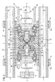
- an electromechanical metering unit 60 is arranged on the opposite side of the first electric drive E Injection bridge 14. With it, the screw conveyor 12 during processing rotated in the plasticizing cylinder 11. Here is a second one Electric drive R provided, its axis also with the spray axis s-s is aligned.
- any other gear can be used. If necessary, can by the use of slow-running motors entirely on a gearbox to be dispensed with.
- the second electric drive R is driven and rotated during dosing as explained at the beginning, the screw conveyor 12.
- the screw conveyor 12 With increasing processed material resulting from the rotation of the screw conveyor accumulates in front of the screw conveyor, the screw conveyor 12 and thus the injection bridge 14 is pushed back.
- the axial Karft on the screw conveyor can be increased or reduced.
- the rod 16e is rotated, the interaction of the Parts of the injection unit 16 an axial movement of the linear movement means 16a arises, which is supported on the support element 18. This movement leads to the desired retraction movement of the screw conveyor 12 or injection unit 16.
- the subsequent injection takes place essentially only by means of the first electric drive E in the way just described.
- the tube 26 can also be used as a power transmission element to relieve or otherwise dimension the rod 16e to be able to.
- this is not in the drawing shown a connection between the threaded sleeve 16b and To create pressure pipe 26, e.g. the forces from the threaded sleeve 16b are transmitted to the spindle head 16c via the planets 16d. The spindle head could then over a collar on an axial bearing element act and transfer the forces to the pipe, as needed can take place by decoupling the linear movement means.
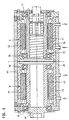
- Fig. 4 shows a further embodiment of the support member 45.
- Das Middle part 45c here is a separate part that has fasteners 62 the outer parts of the injection bridge 14 with the support elements 45 braced.
- the rotors 41, 43 are also in the region of the middle part 45c stored differently.
Description
Im Folgenden wird die Erfindung an Hand der beigefügten Figuren an einem Ausführungsbeispiel näher erläutert. Es zeigen:
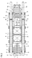
- Fig. 1
- eine Seitenansicht einer auf einem Maschinenfuß abgestützten und an einer Form angelegten Spritzgießeinheit in Seitenansicht,
- Fig. 2
- einen horizontalen Schnitt durch die Spritzgießeinheit in Höhe der Führungsholme,
- Fig. 3
- einen vergrößerten Ausschnitt aus der Darstellung gemäß Fig. 2 im Bereich der Einspritzbrücke,
- Fig. 4
- ein weiteres Ausführungsbeispiels des Tragelements in einer Darstellung gemäß Fig. 3,
- Fig. 5
- eine Darstellung gemäß Fig. 2 in einem weiteren Ausführungsbeispiel,
- Fig. 6
- einen vergrößerten Ausschnitt aus der Darstellung gemäß Fig. 5 im Bereich der Einspritzbrücke.
- 10
- Trägerblock
- 11
- Plastifizierzylinder
- 12
- Förderschnecke
- 13
- Form
- 14
- Einspritzbrücke
- 14a
- Gleitteil
- 15, 50, 52
- Lagerelement
- 16
- elektromechanische Einspritzeinheit
- 16a
- Linearbewegungsmittel
- 16b
- Gewindehülse
- 16c
- Spindelkopf
- 16d
- Planeten
- 16e
- Stange
- 17, 51, 53
- Lagerelement
- 18
- Abstützelement
- 18a
- topfartige Ausnehmung
- 23
- Zwischenzahnräder
- 26
- Rohr
- 27
- Zylinder
- 30
- Ringkolben
- 31
- Holm
- 32, 33
- Zylinderdeckel
- 34
- stationärer Formträger
- 35
- Maschinenfuß
- 37
- Führung
- 39
- Träger
- 41, 43
- Rotor
- 41a, 43a
- Verzahnung
- 42, 44
- Stator
- 45
- Tragelement
- 45a, 45b
- Ausnehmungen
- 45c
- Mittelteil
- 46, 47
- Kupplungseinrichtungen
- 48
- Zahnkranz
- 49
- Mitnehmer
- 60
- elektromechanische Dosiereinheit
- 61
- Ausnehmung
- 62
- Befestigungsmittel
- 63,71
- Pfeil
- 64,65,69,70
- Kanal
- 68
- Durchtrittsbereich
- 72
- hohle Welle
- 73,74
- Kühlkanal
- s-s
- Spritzachse
- t-t
- Trennebene
- D
- Kolben-Zylinder-Einheit
- E
- erster Elektroantrieb
- R
- zweiter Elektroantrieb
Claims (13)
- Spritzgießeinheit für eine Spritzgießmaschine zur Verarbeitung von Kunststoffen und anderen plastifizierbaren Massen mitdadurch gekennzeichnet, dass die Elektroantriebe (E, R) an der Einspritzbrükke (14) beidseits von einer sich im Wesentlichen quer zur Spritzachse erstrekkenden Trennebene (t-t) angeordnet sind, die den Einflussbereich des ersten Elektroantriebs (E) vom Einflussbereich des anderen Elektroantriebs (R) trennt, und dass das Linearbewegungsmittel (16a) außerhalb der Einspritzbrücke (14) an einem Abstützelement (18) abgestützt ist, das Teil eines den Trägerblock (10) umfassenden Kraftrahmens ist, der zugleich der Einspritzbrücke (14) als Führung dient.einem Trägerblock (10) zur Aufnahme eines Plastifizierzylinders (11),einer im Plastifizierzylinder (11) entlang einer Spritzachse (s-s) angeordneten Förderschnecke (12) zum Einspritzen der plastifizierbaren Masse in eine Form (13),einer axial entlang der Spritzachse (s-s) beweglichen Einspritzbrücke (14), an der die Förderschnecke (12) drehbeweglich über wenigstens ein Lagerelement (15) gelagert ist,einer elektromechanischen Einspritzeinheit (16) zum axialen Bewegen von Einspritzbrücke (14) und Förderschnecke (12) mittels eines von einem ersten Elektroantrieb (E) angetriebenen Linearbewegungsmittel (16a) wobei die Achse des ersten Elektroantriebs (E) mit der Spritzachse (s-s) fluchtet,einer elektromechanischen Dosiereinheit (60) zum Drehen der Förderschnecke (12) mittels eines zweiten Elektroantriebs (R), dessen Achse ebenfalls mit der Spritzachse (s-s) fluchtet,
- Spritzgießeinheit nach Anspruch 1, dadurch gekennzeichnet, daß die Elektroantriebe (E,R) Rücken an Rücken in Ausnehmungen (45a,45b) eines Tragelements (45) der Einspritzbrücke (14) aufgenommen sind.
- Spritzgießeinheit nach Anspruch 1, dadurch gekennzeichnet, daß die Elektroantriebe (E, R) weitgehend baugleich sind.
- Spritzgießeinheit nach Anspruch 1, dadurch gekennzeichnet, daß die Elektroantriebe (E, R) mit zugehörigem Planetengetriebe eine bauliche Einheit bilden.
- Spritzgießeinheit nach Anspruch 1, dadurch gekennzeichnet, daß das mit einem Rotor (41) des ersten Elektroantriebs (E) verbundene Linearbewegungsmittel (16a) der Einspritzeinheit (16) einen Spindelkopf (16c) aufweist, der in ein als Gewindehülse (16b) ausgebildetes und mit dem Linearbewegungsmittel zusammenwirkendes Element eintaucht, das am Abstützelement (18) drehfest abgestützt ist.
- Spritzgießeinheit nach Anspruch 5, dadurch gekennzeichnet, daß zwischen Spindelkopf (16c) und Gewindehülse (16b) mehrere mit diesem zusammenwirkende Planeten (16d) angeordnet sind.
- Spritzgießeinheit nach Anspruch 5, dadurch gekennzeichnet, daß eine Stange (16e) des Linearbewegungsmittels (16a) den Spindelkopf (16c) trägt und koaxial zur Achse der Stange (16e) von einem drehfest an der Einspritzbrücke (14) abgestützten Rohr (26) umgeben ist, das in jeder Stellung der Einspritzeinheit (16) in das Abstützelement (18) eintaucht.
- Spritzgießeinheit nach Anspruch 1, dadurch gekennzeichnet, daß eine hydraulische Kolben-Zylinder-Einheit (D) zum Anlegen der Spritzgießeinheit an die Form (13) vorgesehen ist, deren Zylinder (27) auf den stationären, als Holme (31) ausgebildeten Kolbenstangen axial beweglich sind und mit Trägerblock (10) und Abstützelement (18) einen Rahmen bilden.
- Spritzgießeinheit nach Anspruch 8, dadurch gekennzeichnet, daß der Trägerblock (10) im Bereich der vorderen Zylinderdeckel (32) und das Abstützelement (18) im Bereich der hinteren Zylinderdeckel (33) festgelegt ist, und daß die Einspritzbrücke (14) zwischen Trägerblock (10) und Abstützelement (18) auf den Zylindern (27) der Kolben-Zylinder-Einheit (D) axial beweglich ist und rotatorisch abgestützt ist.
- Spritzgießeinheit nach Anspruch 1, dadurch gekennzeichnet, daß wenigstens einer der Elektroantriebe (E,R) ein Hohlwellenmotor ist.
- Spritzgießeinheit nach Anspruch 10, dadurch gekennzeichnet, daß die Länge der Hohlwelle dem maximalen Hub der Förderschnecke (12) entspricht.
Applications Claiming Priority (3)
| Application Number | Priority Date | Filing Date | Title |
|---|---|---|---|
| DE19831482 | 1998-07-14 | ||
| DE19831482A DE19831482C1 (de) | 1998-07-14 | 1998-07-14 | Spritzgießeinheit für eine Spritzgießmaschine |
| PCT/EP1999/004797 WO2000003860A1 (de) | 1998-07-14 | 1999-07-08 | Spritzgiesseinheit für eine spritzgiessmaschine |
Publications (2)
| Publication Number | Publication Date |
|---|---|
| EP1097035A1 EP1097035A1 (de) | 2001-05-09 |
| EP1097035B1 true EP1097035B1 (de) | 2002-05-29 |
Family
ID=7873969
Family Applications (1)
| Application Number | Title | Priority Date | Filing Date |
|---|---|---|---|
| EP99936498A Expired - Lifetime EP1097035B1 (de) | 1998-07-14 | 1999-07-08 | Spritzgiesseinheit für eine spritzgiessmaschine |
Country Status (7)
| Country | Link |
|---|---|
| US (1) | US6394780B1 (de) |
| EP (1) | EP1097035B1 (de) |
| JP (1) | JP2002520201A (de) |
| AT (1) | ATE218092T1 (de) |
| CA (1) | CA2337235C (de) |
| DE (2) | DE19831482C1 (de) |
| WO (1) | WO2000003860A1 (de) |
Families Citing this family (19)
| Publication number | Priority date | Publication date | Assignee | Title |
|---|---|---|---|---|
| US7112057B2 (en) * | 2000-05-23 | 2006-09-26 | Bosch Rexroth Ag | Injection unit for a plastic injection moulding machine |
| DE10028066C1 (de) * | 2000-06-07 | 2001-12-20 | Krauss Maffei Kunststofftech | Einspritzaggregat für eine Spritzgießmaschine |
| US6948925B2 (en) * | 2001-02-15 | 2005-09-27 | Mannesmann Plastics Machinery Gmbh | Closing device in an injection moulding machine for plastics |
| TW542778B (en) * | 2001-09-14 | 2003-07-21 | Sumitomo Heavy Industries | Injection apparatus |
| DE10304578B3 (de) * | 2003-02-05 | 2004-03-18 | Demag Ergotech Gmbh | Einspritzaggregat für eine Spritzgießmaschine |
| WO2005018907A1 (en) * | 2003-08-25 | 2005-03-03 | Husky Injection Molding Systems Ltd. | Drive assembly for rotating and translating a shaft |
| DE10342385B3 (de) | 2003-09-13 | 2004-12-09 | Demag Ergotech Gmbh | Einspritzaggregat für eine Spritzgießmaschine |
| US20070296121A1 (en) * | 2006-06-07 | 2007-12-27 | Husky Injection Molding Systems Ltd. | Molding-system drive |
| US20070296281A1 (en) * | 2006-06-07 | 2007-12-27 | Husky Injection Molding Systems Ltd. | Electrical motor |
| KR101115257B1 (ko) * | 2009-02-16 | 2012-02-15 | 엘에스엠트론 주식회사 | 1 실린더형 하이브리드 사출장치 |
| DE102009012482B4 (de) * | 2009-03-12 | 2013-10-17 | Karl Hehl | Spritzgießeinheit für eine Spritzgießmaschine zur Verarbeitung von Kunststoffen |
| US8087919B2 (en) * | 2009-05-28 | 2012-01-03 | Athena Automation Ltd. | Injection unit for an injection molding machine |
| JP2014054643A (ja) * | 2012-09-11 | 2014-03-27 | Ube Machinery Corporation Ltd | ダイカストマシンの射出装置 |
| DE102013107378B4 (de) * | 2013-07-11 | 2022-05-05 | Wittenstein Se | Antriebsvorrichtung und Verwendung einer Antriebsvorrichtung |
| KR101434905B1 (ko) | 2013-08-20 | 2014-08-28 | (주)원일유압 | 사출성형기의 사출실린더 가이드로드 지지장치 |
| CN108081641B (zh) * | 2017-11-07 | 2019-02-01 | 江苏飞博尔新材料科技有限公司 | 一种全螺纹超长螺杆的加工装置以及加工方法 |
| CN110936571B (zh) * | 2019-12-07 | 2023-11-10 | 佛山市顺德区震德精密机械有限公司 | 一种注塑机单缸射胶机构 |
| CN115027003B (zh) * | 2022-05-16 | 2023-07-21 | 江西联塑科技实业有限公司 | 一种管接头注塑模具及模内组装方法 |
| CN117644606B (zh) * | 2024-01-30 | 2024-04-09 | 合肥荣丰包装制品有限公司 | 一种eps泡沫箱生产用压合装置 |
Family Cites Families (7)
| Publication number | Priority date | Publication date | Assignee | Title |
|---|---|---|---|---|
| DE4142927C1 (de) * | 1991-12-24 | 1993-07-01 | Karl 7298 Lossburg De Hehl | |
| US5421712A (en) | 1993-10-05 | 1995-06-06 | Industrial Technology Research Institute | Screw rotating and advancing device for an injection molding machine |
| DE4344335C2 (de) * | 1993-12-23 | 1996-02-01 | Krauss Maffei Ag | Einspritzaggregat für eine Spritzgießmaschine |
| JP2866019B2 (ja) * | 1995-01-27 | 1999-03-08 | 住友重機械工業株式会社 | 電動射出成形機の射出装置 |
| DE19731833C1 (de) * | 1997-07-24 | 1999-01-14 | Karl Hehl | Spritzgießeinheit für eine Spritzgießmaschine |
| US6120277A (en) * | 1997-07-28 | 2000-09-19 | Cincinnatti Milacron Inc. | Hybrid injection molding machine |
| JP3321766B2 (ja) * | 1997-11-13 | 2002-09-09 | 東芝機械株式会社 | 射出成形機の射出装置 |
-
1998
- 1998-07-14 DE DE19831482A patent/DE19831482C1/de not_active Expired - Fee Related
-
1999
- 1999-07-08 CA CA002337235A patent/CA2337235C/en not_active Expired - Fee Related
- 1999-07-08 DE DE59901558T patent/DE59901558D1/de not_active Expired - Lifetime
- 1999-07-08 US US09/743,734 patent/US6394780B1/en not_active Expired - Fee Related
- 1999-07-08 EP EP99936498A patent/EP1097035B1/de not_active Expired - Lifetime
- 1999-07-08 WO PCT/EP1999/004797 patent/WO2000003860A1/de active IP Right Grant
- 1999-07-08 AT AT99936498T patent/ATE218092T1/de active
- 1999-07-08 JP JP2000559987A patent/JP2002520201A/ja active Pending
Also Published As
| Publication number | Publication date |
|---|---|
| CA2337235A1 (en) | 2000-01-27 |
| WO2000003860A1 (de) | 2000-01-27 |
| DE19831482C1 (de) | 2000-01-20 |
| CA2337235C (en) | 2008-05-20 |
| ATE218092T1 (de) | 2002-06-15 |
| DE59901558D1 (de) | 2002-07-04 |
| EP1097035A1 (de) | 2001-05-09 |
| JP2002520201A (ja) | 2002-07-09 |
| US6394780B1 (en) | 2002-05-28 |
Similar Documents
| Publication | Publication Date | Title |
|---|---|---|
| EP1097035B1 (de) | Spritzgiesseinheit für eine spritzgiessmaschine | |
| DE60320596T2 (de) | Spritzgiesseinheit mit einer antriebsanordnung zum drehen und translatorischen verschieben einer welle | |
| EP1755858B1 (de) | Schliesseinheit mit doppelkurbelantrieb | |
| EP2726267B1 (de) | Drehvorrichtung für eine spritzgiessvorrichtung | |
| EP1339537B1 (de) | Einspritzeinheit für eine spritzgiessmaschine | |
| EP1121237B2 (de) | Spritzgiessmaschine mit einem mehrere antriebsgruppen umfassenden modularen aufbau | |
| EP0627289B1 (de) | Spritzgiesseinheit für eine Kunststoff-Spritzgiessmaschine | |
| EP2629954A1 (de) | Spritzgiessmaschine mit wenigstens zwei kniehebelmechanismen | |
| DE10060087C5 (de) | Einspritzaggregat für eine Spritzgießmaschine | |
| DE19731833C1 (de) | Spritzgießeinheit für eine Spritzgießmaschine | |
| EP0853538B1 (de) | Spritzgiessmaschine zur verarbeitung plastifizierbarer massen | |
| EP1744867B1 (de) | Antriebsanordnung für eine einspritzeinheit in einer spritzgiessmaschine | |
| EP0618025B1 (de) | Einpressaggregat | |
| DE60108432T2 (de) | Antriebsvorrichtung für Spritzgiessmaschine | |
| EP0639444B1 (de) | Einspritzaggregat | |
| DE19605747C2 (de) | Antriebseinheit für Plastifizier- und Einspritzeinheiten von Kunststoff-Spritzgießmaschinen | |
| DE19531329C2 (de) | Spritzgießeinheit für eine Spritzgießmaschine | |
| AT403136B (de) | Vorrichtung zum schliessen von formen einer spritzgiessmaschine | |
| EP2719517B1 (de) | Spritzgiessmaschine | |
| EP1210219A1 (de) | Elektrische präzisions-einspritzeinheit | |
| EP0846048A1 (de) | Spritzgiesseinheit für eine kunststoff-spritzgiessmaschine | |
| DE19531335C2 (de) | Spritzgießeinheit für eine Spritzgießmaschine | |
| DE19531326C1 (de) | Spritzgießeinheit für eine Kunststoff-Spritzgießmaschine | |
| WO1997007971A1 (de) | Spritzgiesseinheit für eine kunststoff-spritzgiessmaschine | |
| DE10051101A1 (de) | Einspritzschneckenantrieb für eine Kunststoffspritzgiessmaschine |
Legal Events
| Date | Code | Title | Description |
|---|---|---|---|
| PUAI | Public reference made under article 153(3) epc to a published international application that has entered the european phase |
Free format text: ORIGINAL CODE: 0009012 |
|
| 17P | Request for examination filed |
Effective date: 20010203 |
|
| AK | Designated contracting states |
Kind code of ref document: A1 Designated state(s): AT BE CH CY DE DK ES FI FR GB GR IE IT LI LU MC NL PT SE |
|
| GRAG | Despatch of communication of intention to grant |
Free format text: ORIGINAL CODE: EPIDOS AGRA |
|
| 17Q | First examination report despatched |
Effective date: 20010713 |
|
| GRAG | Despatch of communication of intention to grant |
Free format text: ORIGINAL CODE: EPIDOS AGRA |
|
| GRAH | Despatch of communication of intention to grant a patent |
Free format text: ORIGINAL CODE: EPIDOS IGRA |
|
| GRAH | Despatch of communication of intention to grant a patent |
Free format text: ORIGINAL CODE: EPIDOS IGRA |
|
| GRAA | (expected) grant |
Free format text: ORIGINAL CODE: 0009210 |
|
| AK | Designated contracting states |
Kind code of ref document: B1 Designated state(s): AT CH DE FR GB IT LI |
|
| REF | Corresponds to: |
Ref document number: 218092 Country of ref document: AT Date of ref document: 20020615 Kind code of ref document: T |
|
| REG | Reference to a national code |
Ref country code: GB Ref legal event code: FG4D Free format text: NOT ENGLISH |
|
| REG | Reference to a national code |
Ref country code: CH Ref legal event code: EP |
|
| REG | Reference to a national code |
Ref country code: CH Ref legal event code: NV Representative=s name: LUCHS & PARTNER PATENTANWAELTE |
|
| REF | Corresponds to: |
Ref document number: 59901558 Country of ref document: DE Date of ref document: 20020704 |
|
| GBT | Gb: translation of ep patent filed (gb section 77(6)(a)/1977) |
Effective date: 20020830 |
|
| ET | Fr: translation filed | ||
| PLBE | No opposition filed within time limit |
Free format text: ORIGINAL CODE: 0009261 |
|
| STAA | Information on the status of an ep patent application or granted ep patent |
Free format text: STATUS: NO OPPOSITION FILED WITHIN TIME LIMIT |
|
| 26N | No opposition filed |
Effective date: 20030303 |
|
| PGFP | Annual fee paid to national office [announced via postgrant information from national office to epo] |
Ref country code: GB Payment date: 20070730 Year of fee payment: 9 |
|
| PGFP | Annual fee paid to national office [announced via postgrant information from national office to epo] |
Ref country code: FR Payment date: 20080718 Year of fee payment: 10 |
|
| GBPC | Gb: european patent ceased through non-payment of renewal fee |
Effective date: 20080708 |
|
| PG25 | Lapsed in a contracting state [announced via postgrant information from national office to epo] |
Ref country code: GB Free format text: LAPSE BECAUSE OF NON-PAYMENT OF DUE FEES Effective date: 20080708 |
|
| REG | Reference to a national code |
Ref country code: FR Ref legal event code: ST Effective date: 20100331 |
|
| PG25 | Lapsed in a contracting state [announced via postgrant information from national office to epo] |
Ref country code: FR Free format text: LAPSE BECAUSE OF NON-PAYMENT OF DUE FEES Effective date: 20090731 |
|
| REG | Reference to a national code |
Ref country code: DE Ref legal event code: R082 Ref document number: 59901558 Country of ref document: DE Representative=s name: PATENTANWAELTE REINHARDT & POHLMANN PARTNERSCH, DE |
|
| REG | Reference to a national code |
Ref country code: DE Ref legal event code: R082 Ref document number: 59901558 Country of ref document: DE Representative=s name: RPK PATENTANWAELTE REINHARDT, POHLMANN UND KAU, DE Effective date: 20140731 Ref country code: DE Ref legal event code: R082 Ref document number: 59901558 Country of ref document: DE Representative=s name: PATENTANWAELTE REINHARDT & POHLMANN PARTNERSCH, DE Effective date: 20140731 Ref country code: DE Ref legal event code: R081 Ref document number: 59901558 Country of ref document: DE Owner name: KEINATH, RENATE, DE Free format text: FORMER OWNER: HEHL, KARL, 72290 LOSSBURG, VERSTORBEN, DE Effective date: 20140731 |
|
| PGFP | Annual fee paid to national office [announced via postgrant information from national office to epo] |
Ref country code: CH Payment date: 20140722 Year of fee payment: 16 |
|
| PGFP | Annual fee paid to national office [announced via postgrant information from national office to epo] |
Ref country code: IT Payment date: 20140724 Year of fee payment: 16 |
|
| PGFP | Annual fee paid to national office [announced via postgrant information from national office to epo] |
Ref country code: DE Payment date: 20150521 Year of fee payment: 17 |
|
| PGFP | Annual fee paid to national office [announced via postgrant information from national office to epo] |
Ref country code: AT Payment date: 20150722 Year of fee payment: 17 |
|
| REG | Reference to a national code |
Ref country code: CH Ref legal event code: PL |
|
| PG25 | Lapsed in a contracting state [announced via postgrant information from national office to epo] |
Ref country code: CH Free format text: LAPSE BECAUSE OF NON-PAYMENT OF DUE FEES Effective date: 20150731 Ref country code: IT Free format text: LAPSE BECAUSE OF NON-PAYMENT OF DUE FEES Effective date: 20150708 Ref country code: LI Free format text: LAPSE BECAUSE OF NON-PAYMENT OF DUE FEES Effective date: 20150731 |
|
| REG | Reference to a national code |
Ref country code: DE Ref legal event code: R119 Ref document number: 59901558 Country of ref document: DE |
|
| REG | Reference to a national code |
Ref country code: AT Ref legal event code: MM01 Ref document number: 218092 Country of ref document: AT Kind code of ref document: T Effective date: 20160708 |
|
| PG25 | Lapsed in a contracting state [announced via postgrant information from national office to epo] |
Ref country code: DE Free format text: LAPSE BECAUSE OF NON-PAYMENT OF DUE FEES Effective date: 20170201 |
|
| PG25 | Lapsed in a contracting state [announced via postgrant information from national office to epo] |
Ref country code: AT Free format text: LAPSE BECAUSE OF NON-PAYMENT OF DUE FEES Effective date: 20160708 |