EP1120372A2 - Klebeband-Handabroller mit Mehrfachscharnier - Google Patents
Klebeband-Handabroller mit Mehrfachscharnier Download PDFInfo
- Publication number
- EP1120372A2 EP1120372A2 EP01101763A EP01101763A EP1120372A2 EP 1120372 A2 EP1120372 A2 EP 1120372A2 EP 01101763 A EP01101763 A EP 01101763A EP 01101763 A EP01101763 A EP 01101763A EP 1120372 A2 EP1120372 A2 EP 1120372A2
- Authority
- EP
- European Patent Office
- Prior art keywords
- hinge
- adhesive tape
- core
- hand dispenser
- core receiver
- Prior art date
- Legal status (The legal status is an assumption and is not a legal conclusion. Google has not performed a legal analysis and makes no representation as to the accuracy of the status listed.)
- Granted
Links
Images


Classifications
-
- B—PERFORMING OPERATIONS; TRANSPORTING
- B65—CONVEYING; PACKING; STORING; HANDLING THIN OR FILAMENTARY MATERIAL
- B65H—HANDLING THIN OR FILAMENTARY MATERIAL, e.g. SHEETS, WEBS, CABLES
- B65H35/00—Delivering articles from cutting or line-perforating machines; Article or web delivery apparatus incorporating cutting or line-perforating devices, e.g. adhesive tape dispensers
- B65H35/0006—Article or web delivery apparatus incorporating cutting or line-perforating devices
- B65H35/002—Hand-held or table apparatus
- B65H35/0026—Hand-held or table apparatus for delivering pressure-sensitive adhesive tape
-
- B—PERFORMING OPERATIONS; TRANSPORTING
- B65—CONVEYING; PACKING; STORING; HANDLING THIN OR FILAMENTARY MATERIAL
- B65H—HANDLING THIN OR FILAMENTARY MATERIAL, e.g. SHEETS, WEBS, CABLES
- B65H2402/00—Constructional details of the handling apparatus
- B65H2402/50—Machine elements
- B65H2402/51—Joints, e.g. riveted or magnetic joints
-
- B—PERFORMING OPERATIONS; TRANSPORTING
- B65—CONVEYING; PACKING; STORING; HANDLING THIN OR FILAMENTARY MATERIAL
- B65H—HANDLING THIN OR FILAMENTARY MATERIAL, e.g. SHEETS, WEBS, CABLES
- B65H2601/00—Problem to be solved or advantage achieved
- B65H2601/30—Facilitating or easing
- B65H2601/32—Facilitating or easing entities relating to handling machine
- B65H2601/321—Access
Definitions
- the invention relates to a tape dispenser in compact form with simplified Filling option, consisting of an upper shell, a lower shell and a Core take-up for receiving an adhesive tape roll on a core.
- Dispensers for adhesive tape rolls serve the user as a storage container for the adhesive tape rolls themselves and as an application aid for their processing.
- the primary task of a tape dispenser is simple, easy and unrolling and cutting tape strips in the intended for the Application required length.
- Typical embodiments of hand dispensers include as basic elements a supporting housing and a cutting device.
- Hand dispensers are available in several designs, including dispensers with film storage, where the adhesive film is at rest with the adhesive side on a film storage surface, that is directly adjacent to the knife. With these, the film is made with your fingers gripped between the shelf and the film roll, unrolled and then with the adhesive Side over the knife, cutting it and the rest Film piece sticks back on the shelf.
- the disadvantage of this dispenser with storage space is the enlarged outer dimension of the unwinder in the unwinding direction, that for transport and Manufacturing is disadvantageous.
- the compact dispenser With these the film is rolled out of the housing through a small slot, the housing only a little larger than the film roll itself. With these compact dispensers After unrolling, the film with the non-sticky side is drawn over the knife and cut it. The remaining film piece is then about as far the exit slot, how it is removed from the knife and can then can be easily gripped for the next rolling process. When not in use for a long time the protruding film piece can also be glued to the side of the knife opposite side of the outlet slot on the designated support surface be filed.
- the dispenser can e.g. be constructed so that it is in a lid and a shell can be disassembled with a parting plane perpendicular to the roller axis, whereby then the shell usually contains a core receiver on which the roll is attached and the exit slot through which the film must be threaded.
- Disadvantage is in this Case that for filling at least one of the dispenser components from your hand must be placed. This can then be lost, making use of the remaining one Unroller component very uncomfortable. At least there are several Hand movements are necessary to remove the component after changing the reel and threading to put it back in the correct position on the component carrying the role and to close the dispenser.
- the object of the invention is to remedy this, in particular adhesive tape dispenser to be made available in compact form, in which no cumbersome threading is required where no individual parts are set aside when changing the reel need to be done again and again without the alignment work of the unwinding components can be closed.
- the adhesive tape dispenser in compact form then consists of an upper shell, a lower shell and a core receiver for receiving an adhesive tape roll located on a core, the core receiver having at least one leg on which a roller-shaped roller bearing is located.
- the upper shell, the lower shell and the core receiver converge in a hinge, the axis of which runs parallel to the roller core, so that the core receiver is between the upper shell and the lower shell when the adhesive tape dispenser is open.
- the core transducer is fixed in its position in the closed state of the tape hand dispenser by means of an upper and lower shell within the tape hand dispenser. If the dispenser is opened, all components remain connected by the hinge, so they cannot get lost and do not need to be removed when changing the reel.
- the exit slot for the film is formed by a gap between the upper and lower shell when closed. This gap therefore opens wide when the dispenser is opened. If a piece of film is cut to length from the fresh roll and then the dispenser is closed, the film automatically lies in the exit slot without any threading work.
- the core receiver In the closed state, the core receiver is also fixed by the upper and lower shells in such a way that the roller has a fixed, rotatable position in the housing. On the other hand, when the housing is opened, the core receiver is released so that the roll change is possible.
- the core receiver is in the area of the roller bearing divided. In the closed state, this division has no effect because the Core sensor is also fixed laterally by the upper and lower shell. In the open Condition, however, the core transducer can be bent apart due to the division be so that the role can be changed easily.
- the roller bearing is not split and only connected to the hinge with one leg.
- the roller In the open state, on the other hand, the roller can easily move to the side of the roller bearing pushed down and thus replaced.
- a locking mechanism provides the side of the upper and lower shell facing away from the hinge so that these in remain closed even without holding the hand, if e.g. Film is pulled out.
- the pressure is preferred Locking mechanism released and the dispenser opened.
- the locking mechanism can consist of positive or non-positive connections such as snap or locking hooks, spring elements, eyelets or other known constructive solutions.
- the hinge is in the form of a ball-socket geometry educated. This has the advantage that it is easily put together during manufacture can be and that it can be interpreted that in the event of an unforeseen heavy stress on the hinge that slides apart rather than break, so that it can then easily be put back together and used again can.
- the hinge is designed as a pin hinge, i.e. one or two parts have pins that are in the eyelets of the other part or the other parts is inserted.
- This construction has the advantage that it is special can be designed smoothly and offers a firm hold.
- the hinge is formed by a Axis on one unwinder component, on the snap eyes of the other unwinder components be plugged on.
- it is very easy to turn with additionally simplified assembly.
- the hinge is constructed asymmetrically. This can be due to different wall thicknesses, additional tabs, protrusions or other geometric changes can be achieved. This is an advantage if the Core transducer may only be installed in the dispenser in a certain direction, because e.g. Arrows are present on the core pick-up which indicate the correct insertion direction for the user show the role. The asymmetry prevents during assembly that the housing is assembled incorrectly.
- the use of the adhesive tape dispenser according to the invention proves to be particularly advantageous for cutting adhesive tapes with simplified and special comfortable roll change.
- the use of the tape dispenser according to the invention is for cutting off of adhesive tapes with most known carriers possible, so carriers Plastic, fabric, fleece or paper.
- FIG. 1 shows an adhesive tape dispenser according to the invention in compact form (1) in the closed state, consisting of an upper shell (2), a lower shell (3) and a core receiver (4) for receiving an adhesive tape roll on a core
- the core receiver (4 ) has at least one leg (41, 42) on which there is a roller-shaped roller bearing (45).
- the core receiver (4) is in the open state of the adhesive tape hand dispenser (1) between the upper shell (2) and the lower shell (3) and the core receiver (4) is also laterally closed by the adhesive tape hand dispenser (1) fixed. All parts come together in a hinge (5), the core receiver (4) being connected to the hinge (5) on the inside in the housing and being fixed in its position by the upper shell (2) and lower shell (3).
- the upper shell (2) also contains a knife (8) for severing the film.
- the outlet slot (6) is formed by a gap between the upper shell (2) and the lower shell (3), the lower shell (3) being immersed in the upper shell (2) with a tab (7) so that the outlet slot is not too far from the knife (8) is removed.
- Upper and lower shells are connected to each other by a locking mechanism in area (9), so that they cannot open automatically when the adhesive film is pulled out. To open the housing, pressure must be exerted on both sides in area (9), see Figure 2.
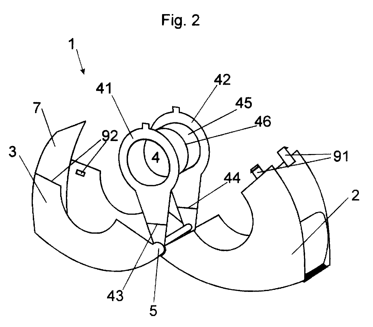
- FIG 2 shows the hand dispenser (1) in the open state with the upper shell (2), lower shell (3) and core sensor (4). All parts converge in the hinge (5), which one here is designed as a ball-pan geometry.
- the two legs (41) and (42) are bent apart by the core receiver (4), which is facilitated here by two film hinges (43) and (44). Doing so opens the roller bearing (45) in the area of the division (46) and the empty film roll (here not drawn) can be exchanged for a full one. Then be the legs (41) and (42) compressed again, a few centimeters of film from the Cut the roll to length and then press the upper shell (2) and lower shell (3) back together.
- the core receiver (4) is then brought back into its fixed position (see figure 1).
- the division (46) can also easily interlock, to deform the core receiver (4) during use of the unwinder (1) largely reduced.
- the hooks (91) snap into the recesses (92) so that the upper and lower shells (2, 3) are firmly connected again are.
- the cut piece of film is automatically inserted into the exit slot led, which forms on the tab (7) which dips into the upper shell (2).
- the film change only consists of the Open the handle, change the roll, cut the film to length, close it and is therefore very convenient. No parts can be lost and no parts of the Rollers are put down from the hand.
- FIG. 3 shows on the basis of a rectangular unwinder geometry in the opened state, how the core receiver (14) can also be designed in one piece and the roller laterally parallel to the roller axis:
- the manual dispenser (11) also consists of Upper shell (12), lower shell (13) and core receiver (14), which in the hinge (15) converge.
- Core sensor (14) consists of only one leg (15) the roller bearing (16) carries.
- the roller bearing is open on the side and can - when open Housing - easily release the film roll.
- the Torsional stiffness of the core receiver (14) improved by recesses (17) that are placed on both sides in both shells and the Secure core holder against slipping.
- the locking mechanism for the Housing is not shown here.
- FIG. 4 shows a hinge (5) in detail, which is designed as a ball-socket geometry is.
- the sections of the upper shell (22), lower shell (23) and Nuclear transducer (24) in an exploded view.
- the lower shell (23) has two spherical ones Wells (25) into which the outer spherical curvatures (26) of the upper shell (22) can be easily turned.
- the upper shell (22) in turn faces inside also two spherical bulges (27) over which the spherical depressions (28) of the core receiver (24) can be inserted.
- Hinge which can be easily put together during assembly and in the case the application of larger forces (e.g.
- the axis (29) has here the function of a support so that the hinge does not slide apart too easily can.
- the entire hinge can be constructed asymmetrically (different Wall thicknesses on both sides or additional tabs), so that the core sensor (24) can only be inserted in the correct position.
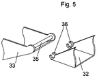
- FIG. 5 shows a hinge (5) in detail, which is formed by an axis which in Snap eyelets (36) is held. Only the sections of the upper shell can be seen here (32) and lower shell (33) in an exploded view.
- the lower shell (33) has an axis (35) into which the snap eyelets (36) of the upper shell (32) can snap.
- the Core pickup (not shown here) has analog snap eyelets that point to the Axis (35) can be inserted.
- a hinge results, which in the Assembly can be easily plugged together and larger in case of application Forces (e.g. fall) can be released without destruction, so that it can be easily reassembled and can continue to be used.
- the entire hinge can be constructed asymmetrically be (different wall thicknesses on both sides or additional Tabs) so that the core sensor can only be inserted in the correct position.
Landscapes
- Adhesive Tape Dispensing Devices (AREA)
- Adhesive Tapes (AREA)
- Unwinding Webs (AREA)
Abstract
Description
Die Oberschale, die Unterschale und der Kemaufnehmer laufen in einem Scharnier zusammen, dessen Achse parallel zum Rollenkem verläuft, so daß sich der Kernaufnehmer im geöffneten Zustand des Klebeband-Handabrollers zwischen der Oberschale und der Unterschale befindet. Der Kemaufnehmer wird im geschlossenen Zustand des Klebeband-Handabrollers durch Ober- und Unterschale innerhalb des Klebeband-Handabrollers in seiner Position fixiert.
Wird der Abroller geöffnet, so bleiben alle Bestandteile durch das Scharnier miteinander verbunden, können somit nicht verlorengehen und brauchen beim Rollenwechsel nicht abgelegt werden. Der Austrittschlitz für den Film wird durch einen Spalt zwischen Ober- und Unterschale im geschlossenen Zustand gebildet. Daher öffnet sich dieser Spalt beim Öffnen des Abrollers weit. Wenn ein Stück Film von der frischen Rolle abgelängt wird und dann der Abroller geschlossen wird, liegt der Film dadurch automatisch im Austrittschlitz ohne jede Einfädelarbeit. Im geschlossenen Zustand wird zudem der Kernaufnehmer durch Ober- und Unterschale so fixiert, daß die Rolle im Gehäuse eine feste drehbare Position einnimmt. Beim Aufklappen des Gehäuses hingegen wird der Kernaufnehmer freigegeben, so daß der Rollenwechsel möglich wird.
- Figur 1
- einen erfindungsgemäßen Klebeband-Handabroller, geschlossen;
- Figur 2
- einen erfindungsgemäßen Handabroller, geöffnet, mit geteiltem Kernaufnehmer und Filmschamieren;
- Figur 3
- einen erfindungsgemäßen Handabroller, geöffnet, mit einteiligem Kernaufnehmer;
- Figur 4
- ein in Kugel-Pfanne-Geometrie ausgeführtes Scharnier;
- Figur 5
- ein Scharnier mit in Schnappösen gehaltener Achse.
Alle Teile laufen in einem Scharnier (5) zusammen, wobei der Kernaufnehmer (4) innen im Gehäuse mit dem Scharnier (5) verbunden ist und in seiner Position von Oberschale (2) und Unterschale (3) fixiert wird. Die Oberschale (2) enthält zudem ein Messer (8) zum Durchtrennen des Filmes. Der Austrittschlitz (6) wird gebildet durch einen Spalt zwischen Oberschale (2) und Unterschale (3), wobei die Unterschale (3) hier mit einer Lasche (7) in die Oberschale (2) eintaucht, damit der Austrittschlitz nicht zu weit vom Messer (8) entfernt ist. Ober- und Unterschale werden durch einen Verschlußmechanismus im Bereich (9) miteinander verbunden, so daß sie sich nicht selbständig öffnen können, wenn Klebefilm herausgezogen wird. Zum Öffnen des Gehäuses muß auf beiden Seiten im Bereich (9) Druck ausgeübt werden, s. Figur 2.
Claims (9)
- Klebeband-Handabroller in Kompaktform, bestehend aus einer Oberschale, einer Unterschale und einem Kernaufnehmer zur Aufnahme einer auf einem Kem befindlichen Klebebandrolle, dadurch gekennzeichnet, daßa) der Kemaufnehmer mindestens einen Schenkel aufweist, an dem sich eine walzenförmige Rollenlagerung befindet,b) die Oberschale, die Unterschale und der Kemaufnehmer in einem Scharnier zusammenlaufen, dessen Achse parallel zum Rollenkern verläuft, so daß sich der Kemaufnehmer im geöffneten Zustand zwischen der Oberschale und der Unterschale befindet und der Kernaufnehmer im geschlossenen Zustand durch Ober- und Unterschale innerhalb des Klebeband-Handabrollers in seiner Position fixiert wird,c) alle Teile im geöffneten Zustand vom Scharnier zusammengehalten werden,d) der Austrittschlitz für den Klebefilm durch einen Spalt zwischen Ober- und Unterschale im geschlossenen Zustand gebildet wird.
- Klebeband-Handabroller nach Anspruch 1, dadurch gekennzeichnet, daß der Kernaufnehmer im Bereich der Rollenlagerung geteilt ist und auseinandergebogen werden kann, wenn sich der Klebeband-Handabroller im geöffneten Zustand befindet.
- Klebeband-Handabroller nach Anspruch 2, dadurch gekennzeichnet, daß zumindest einer der Schenkel des Kernaufnehmers ein zusätzliches Filmscharnier aufweist, dessen Drehachse senkrecht zur Rollenachse liegt und einen Winkel von mehr als 40° mit der Verbindung von Rollenlager und Scharnier bildet.
- Klebeband-Handabroller nach Anspruch 1, dadurch gekennzeichnet, daß der Kernaufnehmer im geöffneten Zustand die Rolle seitlich parallel zur Rollenachse freigibt.
- Klebeband-Handabroller nach mindestens einem der Ansprüche 1 bis 4, dadurch gekennzeichnet, daß ein Verschlußmechanismus auf der dem Scharnier abgewandten Seite Ober- und Unterschale miteinander im geschlossenen Zustand verbindet und diese Verbindung insbesondere durch Ausübung von Druck freigegeben wird.
- Klebeband-Handabroller nach mindestens einem der Ansprüche 1 bis 5, dadurch gekennzeichnet, daß das Scharnier als Kugel-Pfanne-Geometrie ausgebildet ist.
- Klebeband-Handabroller nach mindestens einem der Ansprüche 1 bis 5, dadurch gekennzeichnet, daß das Scharnier als Stiftschamier ausgebildet ist.
- Klebeband-Handabroller nach mindestens einem der Ansprüche 1 bis 5, dadurch gekennzeichnet, daß das Scharnier gebildet ist durch eine Achse, die in Schnappösen gehalten wird.
- Klebeband-Handabroller nach mindestens einem der Ansprüche 1 bis 8, dadurch gekennzeichnet, daß das Scharnier durch unterschiedliche Wandstärken oder Vorsprünge asymmetrisch geformt ist.
Applications Claiming Priority (2)
| Application Number | Priority Date | Filing Date | Title |
|---|---|---|---|
| DE10003753 | 2000-01-28 | ||
| DE10003753A DE10003753A1 (de) | 2000-01-28 | 2000-01-28 | Klebeband-Handabroller mit Mehrfachscharnier |
Publications (3)
| Publication Number | Publication Date |
|---|---|
| EP1120372A2 true EP1120372A2 (de) | 2001-08-01 |
| EP1120372A3 EP1120372A3 (de) | 2002-11-06 |
| EP1120372B1 EP1120372B1 (de) | 2005-04-13 |
Family
ID=7629067
Family Applications (1)
| Application Number | Title | Priority Date | Filing Date |
|---|---|---|---|
| EP01101763A Expired - Lifetime EP1120372B1 (de) | 2000-01-28 | 2001-01-26 | Klebeband-Handabroller mit Mehrfachscharnier |
Country Status (3)
| Country | Link |
|---|---|
| EP (1) | EP1120372B1 (de) |
| DE (2) | DE10003753A1 (de) |
| ES (1) | ES2239072T3 (de) |
Families Citing this family (1)
| Publication number | Priority date | Publication date | Assignee | Title |
|---|---|---|---|---|
| JP7547790B2 (ja) * | 2020-06-01 | 2024-09-10 | コクヨ株式会社 | テープ巻き替え器 |
Family Cites Families (7)
| Publication number | Priority date | Publication date | Assignee | Title |
|---|---|---|---|---|
| US2889975A (en) * | 1953-09-09 | 1959-06-09 | Johnson & Johnson | Tape dispenser |
| GB783204A (en) * | 1955-04-13 | 1957-09-18 | Ofrex Ltd | New or improved label dispensing device |
| DE8700863U1 (de) * | 1987-01-20 | 1988-05-26 | Beiersdorf Ag, 2000 Hamburg | Klebeband-Abroller |
| FR2695114B1 (fr) * | 1992-08-28 | 1994-12-02 | Fourneau Forges Fonderies Haut | Distributeur de papier en rouleau. |
| AU3106093A (en) * | 1993-01-06 | 1994-07-21 | Shuh-Chin Lin | Tape dispenser of packaging |
| FR2710331B3 (fr) * | 1993-09-21 | 1995-08-25 | Shih Sheng Hsiung | Dérouleur de ruban adhésif. |
| US5707482A (en) * | 1996-05-16 | 1998-01-13 | Fusselman; Stephen M. | Removable highlighting tape |
-
2000
- 2000-01-28 DE DE10003753A patent/DE10003753A1/de not_active Withdrawn
-
2001
- 2001-01-26 DE DE50105868T patent/DE50105868D1/de not_active Expired - Lifetime
- 2001-01-26 EP EP01101763A patent/EP1120372B1/de not_active Expired - Lifetime
- 2001-01-26 ES ES01101763T patent/ES2239072T3/es not_active Expired - Lifetime
Also Published As
| Publication number | Publication date |
|---|---|
| DE50105868D1 (de) | 2005-05-19 |
| DE10003753A1 (de) | 2001-08-09 |
| EP1120372A3 (de) | 2002-11-06 |
| EP1120372B1 (de) | 2005-04-13 |
| ES2239072T3 (es) | 2005-09-16 |
Similar Documents
| Publication | Publication Date | Title |
|---|---|---|
| DE69718266T2 (de) | Apparat zum Spenden von Toilettenpapier von Rollen | |
| DE2003354C3 (de) | Vorrichtung zum Abziehen flexiblen blattförmigen Materials | |
| DE60212554T2 (de) | Tragschlitten für Rollen absorbierenden Schichtmaterials und Abgabevorrichtung mit diesem Schlitten | |
| DE1753094A1 (de) | Rolle fuer biegsames Bandmaterial mit Innenabstuetzung | |
| DE4013935C2 (de) | Bandspender | |
| DE1160677B (de) | Kassetteneinrichtung fuer bandfoermige Aufzeichnungstraeger | |
| DE2303386B2 (de) | Halter für einen Streifenwickel zum Abreißen von Streifenstücke bestimmter Länge | |
| DE3312064A1 (de) | Dose zur aufbewahrung von fotographischen filmen u. dgl. | |
| EP2103558A2 (de) | Klebeband-Handabroller in Kompaktform | |
| DE102010051971A1 (de) | Filmübertragungsgerät | |
| DE673012C (de) | Filmtellerkern | |
| DE69303000T2 (de) | Spender für Klebeband in Rollen mit Kernen von verschiedenen Durchmessern | |
| EP1120372B1 (de) | Klebeband-Handabroller mit Mehrfachscharnier | |
| DE202004000491U1 (de) | Bandaufwickelvorrichtung | |
| DE202016100471U1 (de) | Tragbarer Bandabroller | |
| DE69301705T2 (de) | Rollenpapierspender | |
| DE2931053A1 (de) | Abgabevorrichtung fuer blattfoermiges, insbesondere auf einem halter aufgebrachtes material | |
| DE2712622A1 (de) | Kassettenanordnung mit adapter | |
| DE60306688T2 (de) | Vorrichtung zur ausgabe zweiseitiger klebekomponenten eines klebstoffs | |
| DE69013820T2 (de) | Bandkassette. | |
| DE19946272A1 (de) | Eine Vorrats-Toilettenpapier- oder eine Vorrats-Küchenpapierrolle, sowie die daraus resultierenden Toiletten- oder Küchenpapierrollen und deren Herstellungsverfahren | |
| DE2804136C2 (de) | Kassette | |
| DE602005003646T2 (de) | Stift mit Papierrolle | |
| EP0785892B1 (de) | Vorrichtung zur ausgabe von etiketten | |
| DE9405322U1 (de) | Packschachtel |
Legal Events
| Date | Code | Title | Description |
|---|---|---|---|
| PUAI | Public reference made under article 153(3) epc to a published international application that has entered the european phase |
Free format text: ORIGINAL CODE: 0009012 |
|
| AK | Designated contracting states |
Kind code of ref document: A2 Designated state(s): AT BE CH CY DE DK ES FI FR GB GR IE IT LI LU MC NL PT SE TR |
|
| AX | Request for extension of the european patent |
Free format text: AL;LT;LV;MK;RO;SI |
|
| RAP1 | Party data changed (applicant data changed or rights of an application transferred) |
Owner name: TESA AG |
|
| PUAL | Search report despatched |
Free format text: ORIGINAL CODE: 0009013 |
|
| AK | Designated contracting states |
Kind code of ref document: A3 Designated state(s): AT BE CH CY DE DK ES FI FR GB GR IE IT LI LU MC NL PT SE TR |
|
| AX | Request for extension of the european patent |
Free format text: AL;LT;LV;MK;RO;SI |
|
| 17P | Request for examination filed |
Effective date: 20030506 |
|
| AKX | Designation fees paid |
Designated state(s): DE ES FR GB IT |
|
| 17Q | First examination report despatched |
Effective date: 20040120 |
|
| GRAP | Despatch of communication of intention to grant a patent |
Free format text: ORIGINAL CODE: EPIDOSNIGR1 |
|
| RAP1 | Party data changed (applicant data changed or rights of an application transferred) |
Owner name: TESA AG |
|
| RIN1 | Information on inventor provided before grant (corrected) |
Inventor name: WOLF, THEODOR Inventor name: LEIBER, JOERN DR. |
|
| GRAS | Grant fee paid |
Free format text: ORIGINAL CODE: EPIDOSNIGR3 |
|
| GRAA | (expected) grant |
Free format text: ORIGINAL CODE: 0009210 |
|
| AK | Designated contracting states |
Kind code of ref document: B1 Designated state(s): DE ES FR GB IT |
|
| REG | Reference to a national code |
Ref country code: GB Ref legal event code: FG4D Free format text: NOT ENGLISH |
|
| REG | Reference to a national code |
Ref country code: IE Ref legal event code: FG4D Free format text: LANGUAGE OF EP DOCUMENT: GERMAN |
|
| REF | Corresponds to: |
Ref document number: 50105868 Country of ref document: DE Date of ref document: 20050519 Kind code of ref document: P |
|
| GBT | Gb: translation of ep patent filed (gb section 77(6)(a)/1977) |
Effective date: 20050518 |
|
| REG | Reference to a national code |
Ref country code: ES Ref legal event code: FG2A Ref document number: 2239072 Country of ref document: ES Kind code of ref document: T3 |
|
| PLBE | No opposition filed within time limit |
Free format text: ORIGINAL CODE: 0009261 |
|
| STAA | Information on the status of an ep patent application or granted ep patent |
Free format text: STATUS: NO OPPOSITION FILED WITHIN TIME LIMIT |
|
| ET | Fr: translation filed | ||
| 26N | No opposition filed |
Effective date: 20060116 |
|
| REG | Reference to a national code |
Ref country code: FR Ref legal event code: CJ Ref country code: FR Ref legal event code: CD |
|
| PGFP | Annual fee paid to national office [announced via postgrant information from national office to epo] |
Ref country code: ES Payment date: 20100125 Year of fee payment: 10 |
|
| PGFP | Annual fee paid to national office [announced via postgrant information from national office to epo] |
Ref country code: FR Payment date: 20100223 Year of fee payment: 10 Ref country code: IT Payment date: 20100125 Year of fee payment: 10 |
|
| PGFP | Annual fee paid to national office [announced via postgrant information from national office to epo] |
Ref country code: GB Payment date: 20100121 Year of fee payment: 10 |
|
| GBPC | Gb: european patent ceased through non-payment of renewal fee |
Effective date: 20110126 |
|
| REG | Reference to a national code |
Ref country code: FR Ref legal event code: ST Effective date: 20110930 |
|
| PG25 | Lapsed in a contracting state [announced via postgrant information from national office to epo] |
Ref country code: FR Free format text: LAPSE BECAUSE OF NON-PAYMENT OF DUE FEES Effective date: 20110131 |
|
| PG25 | Lapsed in a contracting state [announced via postgrant information from national office to epo] |
Ref country code: GB Free format text: LAPSE BECAUSE OF NON-PAYMENT OF DUE FEES Effective date: 20110126 |
|
| PG25 | Lapsed in a contracting state [announced via postgrant information from national office to epo] |
Ref country code: IT Free format text: LAPSE BECAUSE OF NON-PAYMENT OF DUE FEES Effective date: 20110126 |
|
| REG | Reference to a national code |
Ref country code: ES Ref legal event code: FD2A Effective date: 20120220 |
|
| PG25 | Lapsed in a contracting state [announced via postgrant information from national office to epo] |
Ref country code: ES Free format text: LAPSE BECAUSE OF NON-PAYMENT OF DUE FEES Effective date: 20110127 |
|
| PGFP | Annual fee paid to national office [announced via postgrant information from national office to epo] |
Ref country code: DE Payment date: 20130131 Year of fee payment: 13 |
|
| REG | Reference to a national code |
Ref country code: DE Ref legal event code: R119 Ref document number: 50105868 Country of ref document: DE |
|
| REG | Reference to a national code |
Ref country code: DE Ref legal event code: R119 Ref document number: 50105868 Country of ref document: DE Effective date: 20140801 |
|
| PG25 | Lapsed in a contracting state [announced via postgrant information from national office to epo] |
Ref country code: DE Free format text: LAPSE BECAUSE OF NON-PAYMENT OF DUE FEES Effective date: 20140801 |