EP1120133A2 - Trainingsgerät - Google Patents
Trainingsgerät Download PDFInfo
- Publication number
- EP1120133A2 EP1120133A2 EP00128388A EP00128388A EP1120133A2 EP 1120133 A2 EP1120133 A2 EP 1120133A2 EP 00128388 A EP00128388 A EP 00128388A EP 00128388 A EP00128388 A EP 00128388A EP 1120133 A2 EP1120133 A2 EP 1120133A2
- Authority
- EP
- European Patent Office
- Prior art keywords
- training device
- connecting part
- cross
- plastic connecting
- foam block
- Prior art date
- Legal status (The legal status is an assumption and is not a legal conclusion. Google has not performed a legal analysis and makes no representation as to the accuracy of the status listed.)
- Granted
Links
- 239000006260 foam Substances 0.000 claims abstract description 17
- 229920003023 plastic Polymers 0.000 claims abstract description 17
- 239000004033 plastic Substances 0.000 claims abstract description 17
- 238000005096 rolling process Methods 0.000 claims description 8
- 230000007423 decrease Effects 0.000 claims description 3
- 230000008878 coupling Effects 0.000 abstract 2
- 238000010168 coupling process Methods 0.000 abstract 2
- 238000005859 coupling reaction Methods 0.000 abstract 2
- 230000000284 resting effect Effects 0.000 abstract 1
- 238000013459 approach Methods 0.000 description 2
- 235000015095 lager Nutrition 0.000 description 2
- 239000002689 soil Substances 0.000 description 2
- 239000000725 suspension Substances 0.000 description 2
- 238000001746 injection moulding Methods 0.000 description 1
- 238000009413 insulation Methods 0.000 description 1
- 238000000034 method Methods 0.000 description 1
- 230000003287 optical effect Effects 0.000 description 1
Images

Classifications
-
- A—HUMAN NECESSITIES
- A63—SPORTS; GAMES; AMUSEMENTS
- A63B—APPARATUS FOR PHYSICAL TRAINING, GYMNASTICS, SWIMMING, CLIMBING, OR FENCING; BALL GAMES; TRAINING EQUIPMENT
- A63B26/00—Exercising apparatus not covered by groups A63B1/00 - A63B25/00
- A63B26/003—Exercising apparatus not covered by groups A63B1/00 - A63B25/00 for improving balance or equilibrium
-
- A—HUMAN NECESSITIES
- A63—SPORTS; GAMES; AMUSEMENTS
- A63B—APPARATUS FOR PHYSICAL TRAINING, GYMNASTICS, SWIMMING, CLIMBING, OR FENCING; BALL GAMES; TRAINING EQUIPMENT
- A63B22/00—Exercising apparatus specially adapted for conditioning the cardio-vascular system, for training agility or co-ordination of movements
- A63B22/06—Exercising apparatus specially adapted for conditioning the cardio-vascular system, for training agility or co-ordination of movements with support elements performing a rotating cycling movement, i.e. a closed path movement
- A63B22/0605—Exercising apparatus specially adapted for conditioning the cardio-vascular system, for training agility or co-ordination of movements with support elements performing a rotating cycling movement, i.e. a closed path movement performing a circular movement, e.g. ergometers
- A63B2022/0635—Exercising apparatus specially adapted for conditioning the cardio-vascular system, for training agility or co-ordination of movements with support elements performing a rotating cycling movement, i.e. a closed path movement performing a circular movement, e.g. ergometers specially adapted for a particular use
- A63B2022/0641—Exercising apparatus specially adapted for conditioning the cardio-vascular system, for training agility or co-ordination of movements with support elements performing a rotating cycling movement, i.e. a closed path movement performing a circular movement, e.g. ergometers specially adapted for a particular use enabling a lateral movement of the exercising apparatus, e.g. for simulating movement on a bicycle
Definitions
- the invention relates to a training device in the manner of a stationary bike with pedal cranks and with devices for generating a defined rotational resistance and a receiving these facilities Frame or housing which is at least partially opposite the Soil are spring loaded.
- a generic training device is out DE 297 13 828 U1 known.
- Coil springs are provided, which accordingly have a vertical cushioning enable.
- the invention is based on the object, the basic ones To preserve the advantages of such a suspension and one more to create further improvement insofar as the purely vertical Suspension overlaps a translational component in the horizontal direction to become an even more realistic movement behavior of the Device when pedaling.
- This object is achieved in that on or under the housing skid-like curved rolling devices and / or elastic Plastic, especially foam spring blocks, arranged as a bearing are.
- the curvature can be longitudinal, but preferably transverse to the fictitious Direction of travel.
- the spring blocks according to the invention can be in direct contact be arranged to the floor, but on the other hand it is also conceivable that it arranged within the frame below the saddle and the bottom bracket are, if the arrangement only allows, the exercising person to convey swinging movement, as in a similar form in the natural Bike occurs.
- the skid-like rolling device at least partially on a block of foam.
- the effective height of the foam block can be perpendicular to the fictitious Progressively increase the direction of travel outwards.
- the foam also acts as sound insulation and Soil protection.
- Another embodiment of the invention provides that the rolling device is curved like a skid in the fictitious direction of travel.
- rollers are arranged on the frame, which can be brought into engagement with the floor by tilting the housing, so that the training device can be rolled away effortlessly. Conveniently the rolls are stored on the unwinding devices.
- Eye-like holder are attached so that the rolling device on a holding pin extending perpendicular to the fictitious direction of travel are postponed.
- a locking device can be provided which enables a make a rigid connection to the ground if a exercising person wants to stop the vibrating behavior for certain reasons.
- the foam block and the roll-off devices can be form-fitting be connected, for example, approaches of the rolling device in engage corresponding recesses in the foam block or both components are connected during injection molding.
- the bearings have a foam block and comprise a plastic connecting part arranged thereon, wherein the plastic connector on the end of the cross braces can be placed, and in particular it is provided that the plastic connecting part is so skid-like that its effective height relative to the foam block towards the outer ends of the cross struts decreases and accordingly the effective height of the foam block increases.
- a locking pin is arranged in the plastic connecting part a corresponding recess can be snapped into the end region of the cross strut is, whereby the locking process and the inherent elasticity favors is that the locking pin is slotted.
- the plastic connecting part can have an outer end face that covers the end face of the cross strut, and preferably the shape of the End face is adjusted. On the one hand, this makes an appealing optical Conclusion reached and the form fit further improved and a stop against inward movement is formed.
- the plastic connecting part an approach extending inwards along the cross strut with a hole for inserting a fastening screw into a threaded hole the cross strut has.
- a training device shown in Fig. 1 comprises a housing 2, on which a steering column 3 with a handlebar 4 and a saddle column 5 with a Saddle 6 are arranged.
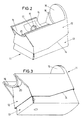
- the housing 2 is mounted on cross struts 9, at their outer ends 10 Bearings 11 are put on.
- Each bearing 11 comprises a plastic connecting part 12 and one hereby connected foam block 13, the height of which via a slope 14 in Direction of the outside of the cross struts 9 increases, as does the effective one The height of the connecting parts decreases.
- the cross struts 9 are round in cross section, and a corresponding one semicircular configuration has the top 14 of the plastic connectors 12 on. At the end, an end face 15 is formed, which the round configuration of the cross struts 9 follows and a support edge 16 for the cross struts 9.
- a locking pin 17 extends from the inside of the upper side 14 a slot 18 up, which in a not shown in the drawing Recess engages in a positive manner on the underside of the cross struts 9.
- An extension 19 extends along the cross strut 9 inwards and points on its underside a bore 20 for inserting a fastening screw in a threaded hole on the underside of the cross strut 9.
Landscapes
- Health & Medical Sciences (AREA)
- General Health & Medical Sciences (AREA)
- Physical Education & Sports Medicine (AREA)
- Cardiology (AREA)
- Vascular Medicine (AREA)
- Rehabilitation Tools (AREA)
- Professional, Industrial, Or Sporting Protective Garments (AREA)
- Devices For Medical Bathing And Washing (AREA)
- Orthopedics, Nursing, And Contraception (AREA)
- Pharmaceuticals Containing Other Organic And Inorganic Compounds (AREA)
- Sliding-Contact Bearings (AREA)
- Bearings For Parts Moving Linearly (AREA)
Abstract
Description
- Fig. 1
- eine perspektivische Ansicht eines erfindungsgemäßen Trainingsgerätes,
- Fig. 2
- eine perspektivische Ansicht eines erfindungsgemäßen Lagers von oben und
- Fig. 3
- eine perspektivische Ansicht eines erfindungsgemäßen Lagers von schräg unten.
Claims (12)
- Trainingsgerät nach Art eines Standfahrrades umfassend ein Gehäuse, welches auf zwei voneinander beanstandeten, parallel zueinander verlaufenden Querstreben gelagert ist, wobei im Endbereich der Querstreben Lager und/oder Rollen angeordnet sind, die am Boden aufstehen, dadurch gekennzeichnet, daß die Lager (11) einen Schaumstoffblock (13) und ein hierauf angeordnetes Kunststoffverbindungsteil (12) umfassen, wobei das Kunststoffverbindungsteil (12) auf das Ende (10) der Querstreben (9) formschlüssig aufsetzbar ist, und wobei insbesondere vorgesehen ist, daß das Kunststoffverbindungsteil (12) derart kufenartig ausgebildet ist, daß dessen affektive Höhe relativ zum Schaumstoffblock (13) in Richtung der äußeren Enden (10) der Querstreben (9) abnimmt und entsprechend die effektive Höhe des Schaumstoffblockes (13) zunimmt.
- Trainingsgerät nach Anspruch 1, dadurch gekennzeichnet, daß das Kunststoffverbindungsteil (12) nach Art einer Halbschale ausgebildet ist, deren Querschnittskonfiguration der Querstrebe (9) angepaßt, insbesondere halbkreisförmig ausgebildet ist.
- Trainingsgerät nach Anspruch 1 oder 2, dadurch gekennzeichnet, daß an der Oberseite des Kunststoffverbindungsteils (12) ein Rastzapfen (17) angeordnet ist, der in eine korrespondierende Ausnehmung im Endbereich der Querstrebe (9) einrastbar ist.
- Trainingsgerät nach Anspruch 3, dadurch gekennzeichnet, daß der Rastzapfen (17) geschlitzt ist.
- Trainingsgerät nach Anspruch 1, dadurch gekennzeichnet, daß das Kunststoffverbindungsteil (12) eine äußere Stirnseite (15) aufweist, die die Stirnseite der Querstrebe (9) abdeckt.
- Trainingsgerät nach Anspruch 5, dadurch gekennzeichnet, daß die Form der Stirnseite (15) der Form der Stirnfläche der Querstreben (9) angepaßt ist.
- Trainingsgerät nach Anspruch 1, dadurch gekennzeichnet, daß das Kunststoffverbindungsteil (12) einen sich längs der Querstrebe nach innen erstreckenden Ansatz (19) mit einer Bohrung (20) zum Einbringen einer Befestigungsschraube in eine Gewindebohrung der Querstrebe (9) aufweist.
- Trainingsgerät insbesondere nach Anspruch 1, dadurch gekennzeichnet, daß die Abroll-Einrichtung in der fiktiven Fahrtrichtung kufenartig gekrümmt ist.
- Trainingsgerät nach Anspruch 8, dadurch gekennzeichnet, daß an der Abroll-Einrichtung ösenartige Halter angebracht sind.
- Trainingsgerät nach Anspruch 8, dadurch gekennzeichnet, daß an dem Gestell Rollen angebracht sind, die durch Kippen des Gestells in Eingriff mit dem Boden gebracht werden.
- Trainingsgerät nach Anspruch 10, dadurch gekennzeichnet, daß die Rollen an den Abroll-Einrichtungen angebracht sind.
- Trainingsgerät nach Anspruch 8, dadurch gekennzeichnet, daß Arretiereinrichtungen zur starren Lagerung gegenüber dem Boden vorgesehen sind.
Applications Claiming Priority (4)
| Application Number | Priority Date | Filing Date | Title |
|---|---|---|---|
| DE10003200 | 2000-01-26 | ||
| DE2000103200 DE10003200A1 (de) | 2000-01-26 | 2000-01-26 | Tainingsgerät nach Art eines Standfahrrads |
| DE20005917U | 2000-03-30 | ||
| DE20005917U DE20005917U1 (de) | 2000-03-30 | 2000-03-30 | Trainingsgerät |
Publications (3)
| Publication Number | Publication Date |
|---|---|
| EP1120133A2 true EP1120133A2 (de) | 2001-08-01 |
| EP1120133A3 EP1120133A3 (de) | 2004-01-07 |
| EP1120133B1 EP1120133B1 (de) | 2005-05-11 |
Family
ID=26004026
Family Applications (1)
| Application Number | Title | Priority Date | Filing Date |
|---|---|---|---|
| EP00128388A Expired - Lifetime EP1120133B1 (de) | 2000-01-26 | 2000-12-22 | Trainingsgerät |
Country Status (3)
| Country | Link |
|---|---|
| EP (1) | EP1120133B1 (de) |
| AT (1) | ATE295205T1 (de) |
| DE (1) | DE50010278D1 (de) |
Family Cites Families (5)
| Publication number | Priority date | Publication date | Assignee | Title |
|---|---|---|---|---|
| NL106927C (de) * | 1958-04-03 | 1900-01-01 | ||
| US4613129A (en) * | 1984-11-09 | 1986-09-23 | Schroeder Charles H | Exercise bicycle attachment |
| FR2602150B1 (fr) * | 1986-07-30 | 1990-07-27 | Maugard Michel | Entraineur cycliste |
| DE19641541A1 (de) * | 1996-10-09 | 1997-06-05 | Edwin Schmidt | Fußschaukel |
| EP0925809B1 (de) * | 1997-12-23 | 2003-11-19 | Federico Gramaccioni | Körperübungsgerät, welches den Gebrauch eines Fahrrads simuliert |
-
2000
- 2000-12-22 AT AT00128388T patent/ATE295205T1/de not_active IP Right Cessation
- 2000-12-22 EP EP00128388A patent/EP1120133B1/de not_active Expired - Lifetime
- 2000-12-22 DE DE50010278T patent/DE50010278D1/de not_active Expired - Lifetime
Also Published As
| Publication number | Publication date |
|---|---|
| ATE295205T1 (de) | 2005-05-15 |
| EP1120133B1 (de) | 2005-05-11 |
| EP1120133A3 (de) | 2004-01-07 |
| DE50010278D1 (de) | 2005-06-16 |
Similar Documents
| Publication | Publication Date | Title |
|---|---|---|
| DE60309188T2 (de) | Fahrradsatteltrügeranordnung | |
| DE102012203859B3 (de) | Faltrad | |
| DD297937A5 (de) | Sitztraeger fuer ein fahrzeug | |
| DE112016000884T5 (de) | Fahrrad mit nachgiebiger Sattelstützen-Verbindung | |
| DE19601635A1 (de) | Vorrichtung zur externen Sicherung gegen Verdrehung, zur Ausfahrbegrenzung und zur Diebstahlsicherung einer hydraulisch positionierbaren Sattelstütze | |
| EP1683662B1 (de) | Haltevorrichtung für einen Stabilisator einer Radaufhängung | |
| EP1120133B1 (de) | Trainingsgerät | |
| DE10155891A1 (de) | Lenksäulenanordnung für ein Fahrzeug | |
| EP3609740B1 (de) | Vorrichtung zur halterung eines zweirads an einem strukturteil | |
| DE202004006563U1 (de) | Fahrrad mit einem zusammenschiebbaren Rahmenrohrsatz | |
| EP0785125A2 (de) | Vorrichtung zur externen Sicherung gegen Verdrehung, zur Ausfahrbegrenzung und zur Diebstahlsicherung einer hydraulisch positionierbaren Sattelstütze | |
| DE102013107302B4 (de) | Zweirad mit einem Trittbrett | |
| DE20005917U1 (de) | Trainingsgerät | |
| DE10003200A1 (de) | Tainingsgerät nach Art eines Standfahrrads | |
| DE202019100638U1 (de) | Vierrädriges Lastenfahrrad | |
| DE20315300U1 (de) | Mehrachsiges zweispuriges Kraftfahrzeug | |
| DE102006055819A1 (de) | Radaufhängung mit beeinflußbarer Vorspur | |
| DE202012104740U1 (de) | Fahrradsattel | |
| DE69505037T2 (de) | Skibindung | |
| DE20205465U1 (de) | Laufrad (Draisine) für Kinder | |
| EP0940332A2 (de) | Zweirädriges Fahrzeug, insbesondere Fahrrad | |
| DE4341028C2 (de) | Fahrradsattel | |
| AT4449U1 (de) | Halterung zum geordneten abstellen von tretrollern | |
| WO2021197688A1 (de) | Lenkeranordnung mit zündlenkschloss für ein neigefahrzeug | |
| DE112005003320T5 (de) | Rollschlitten |
Legal Events
| Date | Code | Title | Description |
|---|---|---|---|
| PUAI | Public reference made under article 153(3) epc to a published international application that has entered the european phase |
Free format text: ORIGINAL CODE: 0009012 |
|
| AK | Designated contracting states |
Kind code of ref document: A2 Designated state(s): AT BE CH CY DE DK ES FI FR GB GR IE IT LI LU MC NL PT SE TR |
|
| AX | Request for extension of the european patent |
Free format text: AL;LT;LV;MK;RO;SI |
|
| RAP1 | Party data changed (applicant data changed or rights of an application transferred) |
Owner name: DAUM GMBH & CO. KG |
|
| PUAL | Search report despatched |
Free format text: ORIGINAL CODE: 0009013 |
|
| RIC1 | Information provided on ipc code assigned before grant |
Ipc: 7A 63B 22/08 A Ipc: 7A 63B 23/04 B |
|
| AK | Designated contracting states |
Kind code of ref document: A3 Designated state(s): AT BE CH CY DE DK ES FI FR GB GR IE IT LI LU MC NL PT SE TR |
|
| AX | Request for extension of the european patent |
Extension state: AL LT LV MK RO SI |
|
| 17P | Request for examination filed |
Effective date: 20040624 |
|
| AKX | Designation fees paid |
Designated state(s): AT BE CH CY DE DK ES FI FR GB GR IE IT LI LU MC NL PT SE TR |
|
| GRAP | Despatch of communication of intention to grant a patent |
Free format text: ORIGINAL CODE: EPIDOSNIGR1 |
|
| GRAS | Grant fee paid |
Free format text: ORIGINAL CODE: EPIDOSNIGR3 |
|
| GRAA | (expected) grant |
Free format text: ORIGINAL CODE: 0009210 |
|
| AK | Designated contracting states |
Kind code of ref document: B1 Designated state(s): AT BE CH CY DE DK ES FI FR GB GR IE IT LI LU MC NL PT SE TR |
|
| PG25 | Lapsed in a contracting state [announced via postgrant information from national office to epo] |
Ref country code: IE Free format text: LAPSE BECAUSE OF FAILURE TO SUBMIT A TRANSLATION OF THE DESCRIPTION OR TO PAY THE FEE WITHIN THE PRESCRIBED TIME-LIMIT Effective date: 20050511 Ref country code: TR Free format text: LAPSE BECAUSE OF FAILURE TO SUBMIT A TRANSLATION OF THE DESCRIPTION OR TO PAY THE FEE WITHIN THE PRESCRIBED TIME-LIMIT Effective date: 20050511 Ref country code: IT Free format text: LAPSE BECAUSE OF FAILURE TO SUBMIT A TRANSLATION OF THE DESCRIPTION OR TO PAY THE FEE WITHIN THE PRESCRIBED TIME-LIMIT;WARNING: LAPSES OF ITALIAN PATENTS WITH EFFECTIVE DATE BEFORE 2007 MAY HAVE OCCURRED AT ANY TIME BEFORE 2007. THE CORRECT EFFECTIVE DATE MAY BE DIFFERENT FROM THE ONE RECORDED. Effective date: 20050511 |
|
| REG | Reference to a national code |
Ref country code: GB Ref legal event code: FG4D Free format text: NOT ENGLISH |
|
| REG | Reference to a national code |
Ref country code: CH Ref legal event code: EP |
|
| GBT | Gb: translation of ep patent filed (gb section 77(6)(a)/1977) |
Effective date: 20050511 |
|
| REG | Reference to a national code |
Ref country code: IE Ref legal event code: FG4D Free format text: LANGUAGE OF EP DOCUMENT: GERMAN |
|
| REF | Corresponds to: |
Ref document number: 50010278 Country of ref document: DE Date of ref document: 20050616 Kind code of ref document: P |
|
| PG25 | Lapsed in a contracting state [announced via postgrant information from national office to epo] |
Ref country code: SE Free format text: LAPSE BECAUSE OF FAILURE TO SUBMIT A TRANSLATION OF THE DESCRIPTION OR TO PAY THE FEE WITHIN THE PRESCRIBED TIME-LIMIT Effective date: 20050811 Ref country code: DK Free format text: LAPSE BECAUSE OF FAILURE TO SUBMIT A TRANSLATION OF THE DESCRIPTION OR TO PAY THE FEE WITHIN THE PRESCRIBED TIME-LIMIT Effective date: 20050811 Ref country code: GR Free format text: LAPSE BECAUSE OF FAILURE TO SUBMIT A TRANSLATION OF THE DESCRIPTION OR TO PAY THE FEE WITHIN THE PRESCRIBED TIME-LIMIT Effective date: 20050811 |
|
| PG25 | Lapsed in a contracting state [announced via postgrant information from national office to epo] |
Ref country code: ES Free format text: LAPSE BECAUSE OF FAILURE TO SUBMIT A TRANSLATION OF THE DESCRIPTION OR TO PAY THE FEE WITHIN THE PRESCRIBED TIME-LIMIT Effective date: 20050822 |
|
| PG25 | Lapsed in a contracting state [announced via postgrant information from national office to epo] |
Ref country code: PT Free format text: LAPSE BECAUSE OF FAILURE TO SUBMIT A TRANSLATION OF THE DESCRIPTION OR TO PAY THE FEE WITHIN THE PRESCRIBED TIME-LIMIT Effective date: 20051019 |
|
| PG25 | Lapsed in a contracting state [announced via postgrant information from national office to epo] |
Ref country code: CY Free format text: LAPSE BECAUSE OF FAILURE TO SUBMIT A TRANSLATION OF THE DESCRIPTION OR TO PAY THE FEE WITHIN THE PRESCRIBED TIME-LIMIT Effective date: 20051222 |
|
| REG | Reference to a national code |
Ref country code: IE Ref legal event code: FD4D |
|
| PG25 | Lapsed in a contracting state [announced via postgrant information from national office to epo] |
Ref country code: LI Free format text: LAPSE BECAUSE OF NON-PAYMENT OF DUE FEES Effective date: 20051231 Ref country code: MC Free format text: LAPSE BECAUSE OF NON-PAYMENT OF DUE FEES Effective date: 20051231 Ref country code: CH Free format text: LAPSE BECAUSE OF NON-PAYMENT OF DUE FEES Effective date: 20051231 Ref country code: BE Free format text: LAPSE BECAUSE OF NON-PAYMENT OF DUE FEES Effective date: 20051231 Ref country code: LU Free format text: LAPSE BECAUSE OF NON-PAYMENT OF DUE FEES Effective date: 20051231 |
|
| PLBE | No opposition filed within time limit |
Free format text: ORIGINAL CODE: 0009261 |
|
| STAA | Information on the status of an ep patent application or granted ep patent |
Free format text: STATUS: NO OPPOSITION FILED WITHIN TIME LIMIT |
|
| ET | Fr: translation filed | ||
| 26N | No opposition filed |
Effective date: 20060214 |
|
| REG | Reference to a national code |
Ref country code: CH Ref legal event code: PL |
|
| PGFP | Annual fee paid to national office [announced via postgrant information from national office to epo] |
Ref country code: GB Payment date: 20061218 Year of fee payment: 7 |
|
| BERE | Be: lapsed |
Owner name: DAUM G.M.B.H. & CO. KG Effective date: 20051231 |
|
| PGFP | Annual fee paid to national office [announced via postgrant information from national office to epo] |
Ref country code: FI Payment date: 20061221 Year of fee payment: 7 |
|
| PG25 | Lapsed in a contracting state [announced via postgrant information from national office to epo] |
Ref country code: FI Free format text: LAPSE BECAUSE OF NON-PAYMENT OF DUE FEES Effective date: 20071222 |
|
| GBPC | Gb: european patent ceased through non-payment of renewal fee |
Effective date: 20071222 |
|
| PG25 | Lapsed in a contracting state [announced via postgrant information from national office to epo] |
Ref country code: GB Free format text: LAPSE BECAUSE OF NON-PAYMENT OF DUE FEES Effective date: 20071222 |
|
| PGFP | Annual fee paid to national office [announced via postgrant information from national office to epo] |
Ref country code: NL Payment date: 20081219 Year of fee payment: 9 |
|
| PGFP | Annual fee paid to national office [announced via postgrant information from national office to epo] |
Ref country code: AT Payment date: 20081120 Year of fee payment: 9 |
|
| PGFP | Annual fee paid to national office [announced via postgrant information from national office to epo] |
Ref country code: FR Payment date: 20081216 Year of fee payment: 9 |
|
| PGFP | Annual fee paid to national office [announced via postgrant information from national office to epo] |
Ref country code: DE Payment date: 20100217 Year of fee payment: 10 |
|
| REG | Reference to a national code |
Ref country code: NL Ref legal event code: V1 Effective date: 20100701 |
|
| PG25 | Lapsed in a contracting state [announced via postgrant information from national office to epo] |
Ref country code: AT Free format text: LAPSE BECAUSE OF NON-PAYMENT OF DUE FEES Effective date: 20091222 |
|
| REG | Reference to a national code |
Ref country code: FR Ref legal event code: ST Effective date: 20100831 |
|
| PG25 | Lapsed in a contracting state [announced via postgrant information from national office to epo] |
Ref country code: FR Free format text: LAPSE BECAUSE OF NON-PAYMENT OF DUE FEES Effective date: 20091231 Ref country code: NL Free format text: LAPSE BECAUSE OF NON-PAYMENT OF DUE FEES Effective date: 20100701 |
|
| REG | Reference to a national code |
Ref country code: DE Ref legal event code: R119 Ref document number: 50010278 Country of ref document: DE Effective date: 20110701 |
|
| PG25 | Lapsed in a contracting state [announced via postgrant information from national office to epo] |
Ref country code: DE Free format text: LAPSE BECAUSE OF NON-PAYMENT OF DUE FEES Effective date: 20110701 |