EP1119735B1 - Anlage zur kondensation von dampf - Google Patents
Anlage zur kondensation von dampf Download PDFInfo
- Publication number
- EP1119735B1 EP1119735B1 EP00963902A EP00963902A EP1119735B1 EP 1119735 B1 EP1119735 B1 EP 1119735B1 EP 00963902 A EP00963902 A EP 00963902A EP 00963902 A EP00963902 A EP 00963902A EP 1119735 B1 EP1119735 B1 EP 1119735B1
- Authority
- EP
- European Patent Office
- Prior art keywords
- installation according
- substructure
- condensate collecting
- tube
- upper tube
- Prior art date
- Legal status (The legal status is an assumption and is not a legal conclusion. Google has not performed a legal analysis and makes no representation as to the accuracy of the status listed.)
- Expired - Lifetime
Links
Images


Classifications
-
- B—PERFORMING OPERATIONS; TRANSPORTING
- B01—PHYSICAL OR CHEMICAL PROCESSES OR APPARATUS IN GENERAL
- B01D—SEPARATION
- B01D5/00—Condensation of vapours; Recovering volatile solvents by condensation
- B01D5/0003—Condensation of vapours; Recovering volatile solvents by condensation by using heat-exchange surfaces for indirect contact between gases or vapours and the cooling medium
- B01D5/0012—Vertical tubes
-
- B—PERFORMING OPERATIONS; TRANSPORTING
- B01—PHYSICAL OR CHEMICAL PROCESSES OR APPARATUS IN GENERAL
- B01D—SEPARATION
- B01D5/00—Condensation of vapours; Recovering volatile solvents by condensation
- B01D5/0003—Condensation of vapours; Recovering volatile solvents by condensation by using heat-exchange surfaces for indirect contact between gases or vapours and the cooling medium
- B01D5/0018—Dome shaped
-
- F—MECHANICAL ENGINEERING; LIGHTING; HEATING; WEAPONS; BLASTING
- F28—HEAT EXCHANGE IN GENERAL
- F28B—STEAM OR VAPOUR CONDENSERS
- F28B1/00—Condensers in which the steam or vapour is separate from the cooling medium by walls, e.g. surface condenser
- F28B1/06—Condensers in which the steam or vapour is separate from the cooling medium by walls, e.g. surface condenser using air or other gas as the cooling medium
-
- F—MECHANICAL ENGINEERING; LIGHTING; HEATING; WEAPONS; BLASTING
- F28—HEAT EXCHANGE IN GENERAL
- F28B—STEAM OR VAPOUR CONDENSERS
- F28B9/00—Auxiliary systems, arrangements, or devices
- F28B9/02—Auxiliary systems, arrangements, or devices for feeding steam or vapour to condensers
-
- F—MECHANICAL ENGINEERING; LIGHTING; HEATING; WEAPONS; BLASTING
- F28—HEAT EXCHANGE IN GENERAL
- F28F—DETAILS OF HEAT-EXCHANGE AND HEAT-TRANSFER APPARATUS, OF GENERAL APPLICATION
- F28F9/00—Casings; Header boxes; Auxiliary supports for elements; Auxiliary members within casings
- F28F9/007—Auxiliary supports for elements
- F28F9/013—Auxiliary supports for elements for tubes or tube-assemblies
Definitions
- the tube bundles are usually under an angle of about 60 ° on the upper platform of a Substructure mounted in the form of a steel framework.
- the distance of the platform from the ground arises the required amount of cooling air to be sucked.
- the upper ends of the tube bundles become fluid-transmitting connected to a common steam distribution line.
- the steam to be condensed over the Steam distribution line passed into the tube bundle and in the mostly tubes finned on the outside of the tube bundles, wherein to reinforce the draft below a certain number of tube bundles approximately in the plane the platform has a fan installed.
- the lower Ends of the tube bundles are depending on their admission on condensate collecting lines or dephlegmator lines connected.
- the environment around a fan is also called a fan field.
- the tube bundles with a width of often about 2.5 Meters and several meters inclination are in the Generally not self-supporting. That's it required to assign a support frame to each tube bundle.
- a support frame usually consists of two oblique stems, by crossbars with each other and are stiffened with the opposite support frame.
- the Support frames must be designed so stable that they additionally to the weights of the tube bundle also the Weights, in any case proportionally, the steam distribution line and the condensate collecting lines and the forces from wind, snow or earthquakes. in addition For the most part, there are also forces from below Steam distribution line crane runways, which are responsible for the Assembly and disassembly of the fans (engine, gearbox) provided are.
- the invention is based on the prior art Task underlying a system for the condensation of steam to create, which is much easier and with simplified Means can be mounted.
- the core of the invention is the fact that now which preferably has a rectangular cross-section Tube bundles are self-supporting, so they not only in its pure form as a heat exchanger used, but at the same time for the removal of static Loads can be used.
- the self-supporting Function of the tube bundle is such that it not only wear themselves, but also the weight of Steam distribution line and the condensate collecting lines (Dephlegmator pipes) and the forces of wind, snow as well as earthquakes and possibly also crane runway loads can.
- the lower height reduces it In addition, the wind and earthquake load for the entire Investment. This is with smaller component dimensions and lower Steel weights connected to the entire system.
- the condensate collecting lines also take over the seal the tube bundle below the lower tube sheets, so far so as to avoid recirculation of Cooling required costly sealing plates can be omitted below the tube bundle.
- Another advantageous feature is that the tube bundles together with the condensate collecting lines can already be pre-assembled at the workshop. This will costly mounting welds and on-site fitting work in the area of the lower tube sheets the tube bundle significantly reduced.
- Another significant advantage of the invention is the limited pivotal support of the opposite Tube bundles over their upper tube sheets. This now leads to the design effort for the possibly changing a bundle pitch, e.g. from process engineering Reasons, is relatively low and fast and can be carried out inexpensively. While at the state of the art counting plant the entire Roof frame geometry would have to be changed, allows the Invention a change in the bundle inclination by simple Adjust the positioning of condensate manifolds to the substructure and the type of mutual Support of the tube bundles over their upper tubesheets.
- angle tabs are at intervals in the longitudinal direction the plant provided. They can be bolted to the tube sheets or welded. A bigger change of Bundling propensity requires only an exchange of these Angle brackets. Nevertheless, the angle tabs allow one limited, usually thermally induced pivoting mobility.
- the upper tube sheets via joint plates connected with each other is in a change the bundle inclination no exchange at all necessary.
- These joint plates are each with support plates with bolted or welded to the tubesheets.
- a preferred embodiment of the condensate collecting lines is in claim 7. You then have one rectangular cross-section on and they are through the bottom tube sheets of the tube bundle, from floor plates and formed from side plates. According to the number of adjacent bundles of tubes, these condensate collecting lines be easily welded together. Both the carrying capacity of the condensate collecting lines as well as the maintenance of the cross section becomes ensured by outside vertical ribs. This but also by a thicker wall of the side panels be achieved.
- the condensate collecting lines instead of a rectangular cross-section, the condensate collecting lines according to the features of claim 8 but also have a triangular cross-section. In this case, the condensate collecting lines are outside also stiffened by vertical ribs. The cross section starting from the tube bundles, it narrows in the direction of to the substructure.
- the condensate collecting lines a round cross section, so they are tube bundle side open formed and next to the open peripheral areas arranged parallel longitudinal webs to the distanced to lower tubesheets. All parts are preferred welded together. Both the condensate collecting lines as well as the longitudinal webs are on the outside by Ribs stiffened.
- the stainless steel angles are directly below the condensate manifolds or arranged at the lower ends of the support feet. They have a vertical and a horizontal leg, with the the rectangular slides from the vertical The middle longitudinal plane of the plant spread over.
- the sliding layers made of polytetrafluoroethylene can point to opposite to the legs of the stainless steel bracket Be provided surfaces. But also conceivable are strip-shaped Overlays.
- the screw according to claim 12 serve as lift-off. Screws can also be used to fix the Slide rails used on the substructure become.
- Another sliding support of the condensate collecting lines provide the features of claim 13. After that are on the substructure upwardly open U-shaped Slide rails releasably or permanently attached. On the ground and on the inner sides of the slide rails are also partially sliding layers of polytetrafluoroethylene intended. Below the condensate collecting lines or the support legs are then guide brackets, in particular made of stainless steel, detachable or non-detachable. There the leadership consoles in the slide rails is Here, too, a perfect support of the tube bundles in Ensured area of condensate collecting lines.
- an embodiment of the invention provides accordingly the features of claim 16 before that the condensate collecting lines on multi - ball bearings at the Substructure are supported.
- These multi-ball bearings can each side of the circumference of the vertical web of a T-shaped Base rail be provided. They are from the vertical legs of a U-shaped slide overlapped, directly or indirectly with a condensate collector connected is.
- the support feet by extending in the direction of the condensate collecting lines U-profiles are formed.
- the U-profiles are then with their legs circumference of the condensate collecting lines at. This way, depending on the inclination the tube bundle an exact position adjustment of the condensate collecting lines be effected to the support feet.
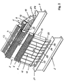
- the plant 1 comprises one of several vertical and horizontal steel beams existing substructure 2.
- the substructure 2 has a platform 3, in whose height range a fan 4 is provided.
- the tube bundles 5 consist of the figures 2, 3, 5, 7 and 9 closer recognizable finned tubes 6 and upper tube plates 7 and lower tube sheets 8 together.
- the tube bundles 5 are fluid-transmitting with its upper ends 9 to a ridge-side Steam distribution line 10 and with their lower Ends 11 connected to condensate collecting lines 12 ( Figure 1).
- the tube bundles 5 are above their upper Tube sheets 7 by a plurality of angle brackets 13 with each other connected.
- the legs 14 of the angle tabs 13 are attached to the upper tube sheets 7 by screw 15.
- the dimensions of the angle tabs 13 are selected that they are the forces of wind, snow as well as earthquakes and the support of the tube bundle 5 against each other can take over, but at the same time soft enough are designed to absorb the thermal expansion of the tube bundle 5 resulting angular rotation in the upper part To allow tube sheets 7.
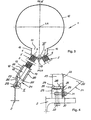
- Support legs 21 To the floor panels 18 of the condensate collecting lines 12th Support legs 21 are welded ( Figures 1 - 3). These Support feet 21 consist of a vertical web plate 22, Outside vertical ribs 23, a lower longitudinal bar 24 and inner stiffening plates 25 and one Stainless steel bracket 26 with a vertical leg 27 and a horizontal leg 28 ( Figures 2-4). With the Stainless steel angles 26, which run the full length of the Support feet 21 can pass or only partially are provided, the condensate collecting 12 forcibly guided on sliding rails 29 which are rectangular in cross section, which are fixed to the substructure 2. At the legs 27, 28 of the stainless steel angle 26 facing Side surfaces of the slide rails 29 are partially Sliding layers 30 provided from polytetrafluoroethylene (Figure 4).
- FIG 4 can still be seen that the support feet 21 by screw means 31 with the slide rails 29 are connected.
- This screw 31 allow Although a relative movement of the support legs 21 to the Slide rails 29, but prevent lifting the tube bundles 5 from the substructure 2.
- the slide rails 29 are via screw 32 on the substructure. 2 attached.
- a support rail 33 is provided is where a crane can be moved along with which e.g. the engine and the gearbox of the fan 4 are interchangeable.
- FIGS. 5, 6 and Fig. 14 differs from that of Figs to 4 and 11 in the connection of the upper tube sheets 7, the cross-sectional design of the condensate collecting lines 12a and the support of the condensate collecting lines 12a on the substructure 2.
- the compound of the upper tube sheets 7 is carried out by the tubesheets 7 screwed trapezoidal profiles 34th ( Figure 14), which are also bolted together. These Profiles 34 are stiffened by webs 35. To the profiles 34, a crane rail 33 according to Figure 1 hung become.
- the provided below the tube bundle 5 condensate collecting lines 12a have a round cross section (FIG 5).
- the tube bundle side are the condensate collecting lines 12a open.
- In addition to the open peripheral areas 36 are parallel longitudinal ridges 37 on the outside of the condensate collecting lines 12a welded, the other on the lower tube sheets 8 are welded.
- Both the Longitudinal webs 37 and the condensate collecting lines 12a are stiffened by outside ribs 38, 39.
- the condensate collecting pipes 12a are longitudinal U-iron 42 welded with her legs 43. These U-iron 42 in turn are on from longitudinal plates 44-46, transverse webs 48 and bottom plates 47 existing support legs 21 a screwed. Below the support feet 21a are several in Longitudinally distributed guide consoles 49th determined by means of screws 50.
- the guide consoles 49 are made of stainless steel. They hold in upwardly open U-shaped Slide rails 29a. Inside of the slide rails 29a are regionally on the bottoms 51 and on the legs 52 Sliding layers 30 of polytetrafluoroethylene intended.
- the slide rails 29a may be the substructure 2 be assigned detachably or permanently.
- connection shown in Figures 5 and 14 can the upper tube plates 7 of Appendix 1a also according to be connected to the figures 3 and 11.
- the condensate collecting pipes 12a can be attached to the substructure 2 be forced, as can be seen from the figures 2 to 4 can be seen.
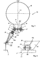
- Condensate manifolds 12b welded with Outside vertical ribs 56 are provided.
- Condensate collecting pipes 12b are around horizontal axes 57 rotatable rollers 58 are provided, the roll on the substructure 2.
- the embodiment of the system 1b according to FIG. 7 can also be used the connections of the upper tube sheets 7 according to the figures 3 and 5 have. Furthermore, the triangular condensate collecting lines 12b according to the embodiments Figures 3 and 5 supported on the substructure 2 be.
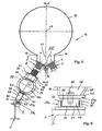
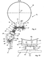
- the plant 1c according to FIGS. 9, 10 and 13 sees likewise in cross-section round condensate collecting lines 12a before, the longitudinal webs 37 to the lower tube sheets 8 distanced and inside by Querverripungen 41st stiffened. On the outside are both the longitudinal webs 37 as well as the condensate collecting lines 12a by ribs 38, 39 stiffened.
- the condensate collecting pipes 12a are welded to the legs 43 of U-iron 42. These are in turn welded to U-profiles 60, which with their Legs 61 ball bearings 62 overlap, on vertical webs 63 provided by T-shaped base rails 64 are.
- the base rails 64 are detachable or non-detachable attached to the substructure 2.
- the upper tube plates 7 are shown in FIGS. 9 and 13 via joint plates 65, 66 connected to each other.
- a double lug 65 provided over a support plate 67 bolted to a tube plate 7 is.
- a single flap 66 which also has a support plate 67 with the other tube plate 7 is screwed.
- the double lug 65 and the single tab 66 are via a pivot pin 68th coupled together.
Landscapes
- Engineering & Computer Science (AREA)
- Mechanical Engineering (AREA)
- General Engineering & Computer Science (AREA)
- Chemical Kinetics & Catalysis (AREA)
- Chemical & Material Sciences (AREA)
- Physics & Mathematics (AREA)
- Thermal Sciences (AREA)
- Supports For Pipes And Cables (AREA)
- Heat-Exchange Devices With Radiators And Conduit Assemblies (AREA)
- Buildings Adapted To Withstand Abnormal External Influences (AREA)
- Vaporization, Distillation, Condensation, Sublimation, And Cold Traps (AREA)
- Thermotherapy And Cooling Therapy Devices (AREA)
- Orthopedics, Nursing, And Contraception (AREA)
- Drying Of Solid Materials (AREA)
- Hydroponics (AREA)
- Non-Silver Salt Photosensitive Materials And Non-Silver Salt Photography (AREA)
- Treatments For Attaching Organic Compounds To Fibrous Goods (AREA)
- Preventing Corrosion Or Incrustation Of Metals (AREA)
Description
Es zeigen:
- Figur 1
- In schematischer Perspektive, teilweise im Schnitt eine Anlage zur Kondensation von Dampf;
- Figur 2
- in vergrößerter Darstellung, teilweise im Schnitt zwei sich firstseitig aneinander abstützende Rohrbündel der Anlage der Figur 1;
- Figur 3
- in vergrößerter Darstellung eine Teil-Stirnansicht auf die Anlage der Figur 1 gemäß dem Pfeil III;
- Figur 4
- den Ausschnitt IV der Figur 3 im vergrößerten Maßstab;
- Figur 5
- eine weitere Ausführungsform einer Anlage entsprechend der Darstellung der Figur 3;
- Figur 6
- in vergrößertem Maßstab den Ausschnitt VI der Figur 5;
- Figur 7
- eine dritte Ausführungsform einer Anlage entsprechend der Darstellung der Figur 3;
- Figur 8
- den Ausschnitt VIII der Figur 7 in vergrößertem Maßstab;
- Figur 9
- eine vierte Ausführungsform einer Anlage entsprechend der Darstellung der Figur 3;
- Figur 10
- den Ausschnitt X der Figur 9 in vergrößertem Maßstab;
- Figur 11
- in der Perspektive in vergrößertem Maßstab den Ausschnitt XI der Figur 3,
- Figur 12
- in der Perspektive in vergrößertem Maßstab den Ausschnitt XII der Figur 7;
- Figur 13
- in der Perspektive in vergrößertem Maßstab den Ausschnitt XIII der Figur 9 und
- Figur 14
- in der Perspektive in vergrößertem Maßstab den Ausschnitt XIV der Figur 5.
- 1 -
- Anlage
- 1a - Anlage
- 1b - Anlage
- 1c - Anlage
- 2 -
- Unterkonstruktion von 1, 1a, 1b, 1c
- 3 -
- Plattform von 2
- 4 -
- Lüfter auf 3
- 5 -
- Rohrbündel
- 6 -
- Rippenrohre von 5
- 7 -
- obere Rohrböden von 5
- 8 -
- untere Rohrböden von 5
- 9 -
- obere Enden von 5
- 10 -
- Dampfverteilleitung
- 11 -
- untere Enden von 5
- 12 -
- Kondensatsammelleitungen
- 12a - Kondensatsammelleitungen
- 12b - Kondensatsammelleitungen
- 13 -
- Winkellaschen
- 14 -
- Schenkel von 13
- 15 -
- Schraubmittel
- 16 -
- Distanzstege
- 17 -
- Umfangsbereich von 10
- 18 -
- Bodenbleche von 12
- 19 -
- Seitenbleche von 12
- 20 -
- Vertikalrippen an 19
- 21 -
- Stützfüße
21a - Stützfüße - 22 -
- Stegblech von 21
- 23 -
- Vertikalrippen
- 24 -
- Längsleiste
- 25 -
- Versteifungsbleche
- 26 -
- Edelstahlwinkel
- 27 -
- vertikale Schenkel von 26
- 28 -
- horizontale Schenkel von 26
- 29 -
- Gleitschienen
29a - Gleitschienen - 30 -
- Gleitschichten an 29, 29a
- 31 -
- Schraubmittel
- 32 -
- Schraubmittel
- 33 -
- Tragschiene
- 34 -
- trapezförmige Profile
- 35 -
- Stege an 34
- 36 -
- offene Umfangsbereiche von 12a
- 37 -
- Längsstege zwischen 12a und 8
- 38 -
- Rippen an 37
- 39 -
- Rippen an 12a
- 40 -
- Wandungen von 12a
- 41 -
- Querverrippung
- 42 -
- U-Eisen (Stützfüße)
- 43 -
- Schenkel von 42
- 44 -
- Längsbleche
- 45 -
- Längsbleche
- 46 -
- Längsbleche
- 47 -
- Bodenbleche
- 48 -
- Querstege
- 49 -
- Führungskonsolen
- 50 -
- Schrauben
- 51 -
- Böden von 29a
- 52 -
- Schenkel von 29 a
- 53 -
- obere Klemmlasche
- 54 -
- untere Klemmlasche
- 55 -
- Schraubmittel
- 56 -
- Vertikalrippen
- 57 -
- Achsen von 58
- 58 -
- Rollen
- 59 -
- Anschlagleisten
- 60 -
- U-Profile
- 61 -
- Schenkel von 60
- 62 -
- Vielkugellager
- 63 -
- Vertikalstege von 64
- 64 -
- Basisschienen
- 65 -
- Doppellasche
- 66 -
- Einfachlasche
- 67 -
- Tragbleche
- 68 -
- Schwenkbolzen
- LA -
- Längsachse von 10
- MLE -
- vertikale Mittellängsebene durch LA
Claims (16)
- Anlage zur Kondensation von Dampf, welche im Abstand vom Erdboden mehrere von einer Unterkonstruktion (2) abgefangene, oberhalb eines Lüfters (4) in A- bzw. spitzdachförmiger Konfiguration angeordnete, selbsttragend ausgebildete Rohrbündel (5) aufweist, die fluidübertragend mit ihren oberen Enden (9) an eine firstseitige Dampfverteilleitung (10) und mit ihren unteren Enden (11) an eine Kondensatsammelleitung (12, 12a, 12b) angeschlossen sind, wobei die bezüglich der durch die Längsachse (LA) der Dampfverteilleitung (10) verlaufenden vertikalen Mittellängsebene (MLE) einander gegenüberliegenden Rohrbündel (5) sich über ihre oberen Rohrböden (7) begrenzt schwenkgelenkig aneinander abstützen und die Kondensatsammelleitungen (12, 12a, 12b) unterhalb der unteren Rohrböden (8) an diese angesetzt sowie parallel zur Mittellängsebene (MLE) relativ verlagerbar auf der Unterkonstruktion (2) positioniert sind.
- Anlage nach Anspruch 1, bei welcher die oberen Rohrböden (7) über Winkellaschen (13) miteinander verbunden sind.
- Anlage nach Anspruch 1, bei welcher die oberen Rohrböden (7) durch diese über- und untergreifende, miteinander verschraubte Klemmlaschen (53, 54) gekoppelt sind.
- Anlage nach Anspruch 1, bei welcher die oberen Rohrböden (7) über Gelenklaschen (65, 66) miteinander verbunden sind.
- Anlage nach Anspruch 1, bei welcher die oberen Rohrböden (7) durch unter diesen befestigte sowie miteinander verbundene, mittels Stegen (35) ausgesteifte U-förmige Profile (34) aneinander gekoppelt sind.
- Anlage nach einem der Ansprüche 1 bis 5, bei welcher die einen runden Querschnitt aufweisende Dampfverteilleitung (10) im unteren Umfangsbereich (17) offen ausgebildet und über neben dem offenen Umfangsbereich (17) liegende parallele Distanzstege (16) an den oberen Rohrböden (7) befestigt ist.
- Anlage nach einem der Ansprüche 1 bis 6, bei welcher die Kondensatsammelleitungen (12) einen rechteckigen Querschnitt aufweisen und außenseitig durch Vertikalrippen (20) versteift sind.
- Anlage nach einem der Ansprüche 1 bis 6, bei welcher die Kondensatsammelleitungen (12b) einen dreieckigen Querschnitt aufweisen und außenseitig durch Vertikalrippen (56) versteift sind.
- Anlage nach einem der Ansprüche 1 bis 6, bei welcher die Kondensatsammelleitungen (12a) einen runden Querschnitt aufweisen, rohrbündelseitig offen ausgebildet und durch parallele Längsstege (37) zu den unteren Rohrböden (8) distanziert sind, wobei sowohl die Kondensatsammelleitungen (12a) als auch die Längsstege (37) außenseitig durch Rippen (39, 38) versteift sind.
- Anlage nach einem der Ansprüche 1 bis 9, bei welcher die Kondensatsammelleitungen (12, 12a, 12b) direkt oder über Stützfüße (21, 21a, 42) an auf der Unterkonstruktion (2) befestigten Gleitschienen (29, 29a) zwangsgeführt sind.
- Anlage nach Anspruch 10, bei welcher die Stützfüße (21, 21a) über hochglanzpolierte Edelstahlwinkel (26) an den bereichsweise mit Gleitschichten (30) aus Polytetrafluorethylen versehenen, einen rechteckigen Querschnitt aufweisenden Gleitschienen (29) zwangsgeführt sind.
- Anlage nach Anspruch 10 oder 11, bei welcher die Stützfüße (21, 21a) durch eine begrenzte Relativverlagerung zulassende Schraubverbindungen (31) an den Gleitschienen (29) festgelegt sind.
- Anlage nach Anspruch 10, bei welcher die Stützfüße (21, 21a) über Führungskonsolen (49) in nach oben offenen, bereichsweise mit Gleitschichten (30) aus Polytetrafluorethylen versehenen U-förmigen Gleitschienen (29a) zwangsgeführt sind.
- Anlage nach einem der Ansprüche 1 bis 9, bei welcher die Kondensatsammelleitungen (12, 12a, 12b) direkt oder über Stützfüße (21, 21a, 42) rollend auf der Unterkonstruktion (2) gelagert sind.
- Anlage nach Anspruch 14, bei welcher die Kondensatsammelleitungen (12, 12a, 12b) über an den Stützfüßen (21, 21a, 42) vorgesehene Rollen (58) auf der Unterkonstruktion (2) abwälzen.
- Anlage nach Anspruch 14, bei welcher die Kondensatsammelleitungen (12, 12a, 12b) über Vielkugellager (62) an der Unterkonstruktion (2) abgestützt sind.
Applications Claiming Priority (3)
| Application Number | Priority Date | Filing Date | Title |
|---|---|---|---|
| DE19937800A DE19937800B4 (de) | 1999-08-10 | 1999-08-10 | Anlage zur Kondensation von Dampf |
| DE19937800 | 1999-08-10 | ||
| PCT/DE2000/002714 WO2001011300A1 (de) | 1999-08-10 | 2000-08-09 | Anlage zur kondensation von dampf |
Publications (2)
| Publication Number | Publication Date |
|---|---|
| EP1119735A1 EP1119735A1 (de) | 2001-08-01 |
| EP1119735B1 true EP1119735B1 (de) | 2005-02-02 |
Family
ID=7917895
Family Applications (1)
| Application Number | Title | Priority Date | Filing Date |
|---|---|---|---|
| EP00963902A Expired - Lifetime EP1119735B1 (de) | 1999-08-10 | 2000-08-09 | Anlage zur kondensation von dampf |
Country Status (10)
| Country | Link |
|---|---|
| US (1) | US6474272B2 (de) |
| EP (1) | EP1119735B1 (de) |
| JP (1) | JP3995077B2 (de) |
| CN (1) | CN1144015C (de) |
| AT (1) | ATE288576T1 (de) |
| DE (2) | DE19937800B4 (de) |
| ES (1) | ES2234664T3 (de) |
| RU (1) | RU2208751C2 (de) |
| WO (1) | WO2001011300A1 (de) |
| ZA (1) | ZA200102920B (de) |
Families Citing this family (34)
| Publication number | Priority date | Publication date | Assignee | Title |
|---|---|---|---|---|
| DE602005023426D1 (de) | 2004-03-25 | 2010-10-21 | California Inst Of Techn | Hybridisierungskettenreaktion |
| DE102005024156B3 (de) * | 2005-05-23 | 2006-10-19 | Gea Energietechnik Gmbh | Kondensationsanlage |
| US7497250B2 (en) * | 2006-02-23 | 2009-03-03 | Tri-X-Flo, L.L.C. | Triangular shaped heat exchanger |
| CN100451521C (zh) * | 2006-05-26 | 2009-01-14 | 江苏双良空调设备股份有限公司 | 加装进风导流装置的电站直接空冷凝汽器 |
| DE102006029773B3 (de) | 2006-06-27 | 2007-07-12 | Gea Energietechnik Gmbh | Verfahren zur Errichtung einer Kondensationsanlage |
| DE102007012539B4 (de) * | 2007-03-13 | 2011-03-03 | Gea Energietechnik Gmbh | Kondensationsanlage |
| DE102007044658B3 (de) * | 2007-09-18 | 2008-12-04 | Gea Energietechnik Gmbh | Luftbeaufschlagter Trockenkühler |
| DE102007058030A1 (de) | 2007-11-30 | 2009-06-04 | Bohnenstengel, Christel | Abkühlanordnung |
| US7836967B2 (en) | 2008-07-28 | 2010-11-23 | Caterpillar Inc | Cooling system packaging arrangement for a machine |
| WO2010099774A2 (de) * | 2009-03-06 | 2010-09-10 | Gea Energietechnik Gmbh | Luftgekühlte kondensatoranlage und verfahren zum errichten einer solchen kondensatoranlage |
| CN102589344B (zh) * | 2012-03-14 | 2013-07-03 | 山西省电力公司电力科学研究院 | 一种直接空冷系统风机入口百叶窗 |
| US20130292103A1 (en) * | 2012-04-16 | 2013-11-07 | Evapco, Inc. | Apparatus and Method for Connecting Air Cooled Condenser Heat Exchanger Coils to Steam Distribution Manifold |
| US9551532B2 (en) * | 2012-05-23 | 2017-01-24 | Spx Dry Cooling Usa Llc | Modular air cooled condenser apparatus and method |
| JP6178232B2 (ja) * | 2013-12-24 | 2017-08-09 | 株式会社東芝 | 復水器及びその耐震補強方法 |
| DE102014112707A1 (de) | 2014-09-03 | 2016-03-03 | Gea Energietechnik Gmbh | Anlage zur Kondensation von Dampf |
| DE202014104666U1 (de) | 2014-09-29 | 2014-11-19 | Gea Energietechnik Gmbh | Anlage zur Kondensation von Dampf |
| CN106716036B (zh) * | 2014-09-29 | 2018-10-16 | 英能科德国有限公司 | 用于冷凝蒸汽的设备 |
| NL2014379B1 (nl) * | 2015-03-02 | 2016-10-14 | Eco-Logical Entpr B V | Koelinrichting. |
| US10161683B2 (en) | 2015-08-20 | 2018-12-25 | Holtec International | Dry cooling system for powerplants |
| US10132568B2 (en) | 2015-08-20 | 2018-11-20 | Holtec International | Dry cooling system for powerplants |
| CN105758249B (zh) * | 2016-04-18 | 2018-12-21 | 河北水利电力学院 | 直接空冷单元的叶栅型冷却空气导流装置 |
| WO2017202730A1 (en) * | 2016-05-25 | 2017-11-30 | Spx Dry Cooling Belgium | Air-cooled condenser apparatus and method |
| EP3287732B1 (de) * | 2016-08-24 | 2019-10-02 | SPG Dry Cooling Belgium | Durch angesaugte zugluft gekühlter kondensator |
| ES2850201T3 (es) * | 2017-01-30 | 2021-08-26 | Spg Dry Cooling Belgium | Condensador enfriado por aire con difusor de flujo de aire |
| US11796255B2 (en) | 2017-02-24 | 2023-10-24 | Holtec International | Air-cooled condenser with deflection limiter beams |
| US11604030B2 (en) * | 2017-09-27 | 2023-03-14 | Holtec International | Air-cooled condenser system |
| EP3688396B1 (de) * | 2017-09-27 | 2023-07-26 | Holtec International | Luftgekühltes kondensatorsystem |
| CN112553210B (zh) * | 2017-10-03 | 2024-09-24 | 普利维尔治疗公司 | 用于溶酶体障碍的基因疗法 |
| PL3745067T3 (pl) | 2019-05-29 | 2021-09-06 | Ovh | Zespół wymiennika ciepła |
| DK3745070T3 (da) | 2019-05-29 | 2021-08-30 | Ovh | Varmeveksleranordning og fremgangsmåde til samling deraf |
| KR20220146652A (ko) | 2020-03-06 | 2022-11-01 | 홀텍 인터내셔날 | 유도 통풍 공랭식 응축기 시스템 |
| WO2021183452A2 (en) * | 2020-03-09 | 2021-09-16 | Oklo Inc. | Reactor building and vessel systems |
| EP4006332A1 (de) | 2020-11-30 | 2022-06-01 | FlowGen Development & Management AG | Windkraftwerk |
| CN113899222B (zh) * | 2021-11-17 | 2025-04-15 | 杭州国能汽轮工程有限公司 | 一种可释放热位移的a型空冷器 |
Family Cites Families (21)
| Publication number | Priority date | Publication date | Assignee | Title |
|---|---|---|---|---|
| DE1228640B (de) * | 1962-03-14 | 1966-11-17 | Gea Luftkuehler Happel Gmbh | Luftgekuehlter Waermeaustauscher, dessen Axialluefter auf einem Stuetzbock gelagert ist |
| DE1776130A1 (de) * | 1968-09-25 | 1970-10-01 | Borsig Gmbh | Luftgekuehlter Kondensator |
| DE1962061C3 (de) * | 1969-12-11 | 1979-05-10 | Kraftwerk Union Ag, 4330 Muelheim | Luftkondensationsanlage |
| US3939906A (en) * | 1973-12-28 | 1976-02-24 | The Lummus Company | Air cooled exchanger |
| US4000779A (en) * | 1975-11-28 | 1977-01-04 | General Electric Company | Blowoff baffle |
| US4129180A (en) * | 1976-12-06 | 1978-12-12 | Hudson Products Corporation | Vapor condensing apparatus |
| IT1085754B (it) * | 1977-04-26 | 1985-05-28 | Snam Progetti | Condensatore ad aria |
| IT1135516B (it) * | 1981-02-18 | 1986-08-27 | Nuovo Pignone Spa | Condensatore perfezionato di vapore con raffreddamento ad aria |
| US4657070A (en) * | 1984-02-15 | 1987-04-14 | Hudson Products Corporation | Air-cooled vapor condensers |
| DE3414589A1 (de) * | 1984-04-18 | 1984-12-13 | Lothar 4173 Kerken Kehne | Luftgekuehlte kondensationsanlage |
| EP0170753A1 (de) * | 1984-07-30 | 1986-02-12 | Hamon-Sobelco S.A. | Mit Zwangsbelüftung gekühlter Kondensator |
| GB2172391B (en) * | 1985-03-14 | 1988-11-09 | Hudson Products Corp | Air-cooled vapor condensers |
| US4903491A (en) * | 1988-06-13 | 1990-02-27 | Larinoff Michael W | Air-cooled vacuum steam condenser |
| US4905474A (en) * | 1988-06-13 | 1990-03-06 | Larinoff Michael W | Air-cooled vacuum steam condenser |
| EP0369298A1 (de) * | 1988-11-14 | 1990-05-23 | Michael William Larinoff | Luftgekühlter Dampfkondensator mit Vakuum und Schutz gegen Vereisung |
| DE4039292A1 (de) * | 1990-12-08 | 1992-06-11 | Gea Luftkuehler Happel Gmbh | Verfahren zum herstellen eines waermetauschers und vorrichtung zur durchfuehrung des verfahrens |
| RU2045726C1 (ru) * | 1993-01-11 | 1995-10-10 | Предприятие "Кубань-ПромАгроСервис" | Конденсатор |
| RU2119628C1 (ru) * | 1995-11-21 | 1998-09-27 | Олег Ошеревич Мильман | Модуль конденсатора пара мильмана |
| US5653281A (en) * | 1995-12-20 | 1997-08-05 | Hudson Products Corporation | Steam condensing module with integral, stacked vent condenser |
| DE19701598C2 (de) * | 1997-01-18 | 1999-04-08 | Gea Energietechnik Gmbh | Wärmetauscherrohr |
| US5950717A (en) * | 1998-04-09 | 1999-09-14 | Gea Power Cooling Systems Inc. | Air-cooled surface condenser |
-
1999
- 1999-08-10 DE DE19937800A patent/DE19937800B4/de not_active Expired - Lifetime
-
2000
- 2000-08-09 EP EP00963902A patent/EP1119735B1/de not_active Expired - Lifetime
- 2000-08-09 AT AT00963902T patent/ATE288576T1/de active
- 2000-08-09 DE DE50009415T patent/DE50009415D1/de not_active Expired - Lifetime
- 2000-08-09 JP JP2001515515A patent/JP3995077B2/ja not_active Expired - Fee Related
- 2000-08-09 WO PCT/DE2000/002714 patent/WO2001011300A1/de not_active Ceased
- 2000-08-09 ES ES00963902T patent/ES2234664T3/es not_active Expired - Lifetime
- 2000-08-09 CN CNB008016585A patent/CN1144015C/zh not_active Expired - Fee Related
- 2000-08-09 RU RU2001112408/06A patent/RU2208751C2/ru not_active IP Right Cessation
-
2001
- 2001-04-09 ZA ZA200102920A patent/ZA200102920B/en unknown
- 2001-04-10 US US09/832,184 patent/US6474272B2/en not_active Expired - Lifetime
Also Published As
| Publication number | Publication date |
|---|---|
| JP3995077B2 (ja) | 2007-10-24 |
| JP2003506662A (ja) | 2003-02-18 |
| ES2234664T3 (es) | 2005-07-01 |
| DE50009415D1 (de) | 2005-03-10 |
| DE19937800A1 (de) | 2001-02-22 |
| US6474272B2 (en) | 2002-11-05 |
| DE19937800B4 (de) | 2005-06-16 |
| WO2001011300A1 (de) | 2001-02-15 |
| CN1144015C (zh) | 2004-03-31 |
| RU2208751C2 (ru) | 2003-07-20 |
| ZA200102920B (en) | 2002-07-09 |
| ATE288576T1 (de) | 2005-02-15 |
| US20020005176A1 (en) | 2002-01-17 |
| EP1119735A1 (de) | 2001-08-01 |
| CN1320206A (zh) | 2001-10-31 |
Similar Documents
| Publication | Publication Date | Title |
|---|---|---|
| DE19937800B4 (de) | Anlage zur Kondensation von Dampf | |
| EP3201550B1 (de) | Anlage zur kondensation von dampf | |
| DE69319761T2 (de) | Konstruktionsaufbau | |
| DE102018101344A1 (de) | Kühleinheit, Anlage und Verfahren | |
| DE2842411A1 (de) | Waermeaustauscher, insbesondere fuer atmosphaerische kuehler | |
| DE202014104666U1 (de) | Anlage zur Kondensation von Dampf | |
| DE69526670T2 (de) | Kühlturm und konstruktionsverfahren | |
| EP3016843B1 (de) | Überflurfördereinrichtung mit traggerüstmodulen | |
| EP1477746A1 (de) | Arbeitsbühne zur Montage von Sonnenkollektormodulen | |
| DE102014112707A1 (de) | Anlage zur Kondensation von Dampf | |
| DE69817042T2 (de) | Kälteaggregat | |
| DE3826508A1 (de) | Auflagerung einer axial fixierten dampfturbine | |
| DE1939245C3 (de) | Luftgekühlter Kondensator für das Kopf produkt einer Destillier- oder Rektifizier-Kolonne | |
| DE69220445T2 (de) | Wärmetauscher mit beweglichen Röhrenanordnungen | |
| EP3134676B1 (de) | Wärmetauscher | |
| EP1126227A1 (de) | Dampfkondensator | |
| DE102008038663B4 (de) | Wärmetauscher mit einem Rohrbündel aus parallel zueinander verlaufenden, aus Kunststoff bestehenden Rohren | |
| DE140727C (de) | ||
| DE102006005208A1 (de) | Hängender Dampferzeuger | |
| DE102022111503A1 (de) | Kondensationsanlage | |
| EP2218973A2 (de) | Unterflurklimagerät | |
| DE2238451C3 (de) | Luftvorwärmeranlage | |
| CH719083A2 (de) | Deckenstrahlelement mit Rohrmäander. | |
| DE1514501C (de) | Kernreaktoranlage mit Dampferzeuger | |
| EP2250458B1 (de) | Anordnung zur rückkühlung von kühlwasser |
Legal Events
| Date | Code | Title | Description |
|---|---|---|---|
| PUAI | Public reference made under article 153(3) epc to a published international application that has entered the european phase |
Free format text: ORIGINAL CODE: 0009012 |
|
| 17P | Request for examination filed |
Effective date: 20010404 |
|
| AK | Designated contracting states |
Kind code of ref document: A1 Designated state(s): AT BE CH CY DE DK ES FI FR GB GR IE IT LI LU MC NL PT SE |
|
| GRAP | Despatch of communication of intention to grant a patent |
Free format text: ORIGINAL CODE: EPIDOSNIGR1 |
|
| GRAS | Grant fee paid |
Free format text: ORIGINAL CODE: EPIDOSNIGR3 |
|
| GRAA | (expected) grant |
Free format text: ORIGINAL CODE: 0009210 |
|
| AK | Designated contracting states |
Kind code of ref document: B1 Designated state(s): AT BE CH CY DE DK ES FI FR GB GR IE IT LI LU MC NL PT SE |
|
| PG25 | Lapsed in a contracting state [announced via postgrant information from national office to epo] |
Ref country code: FI Free format text: LAPSE BECAUSE OF FAILURE TO SUBMIT A TRANSLATION OF THE DESCRIPTION OR TO PAY THE FEE WITHIN THE PRESCRIBED TIME-LIMIT Effective date: 20050202 |
|
| REG | Reference to a national code |
Ref country code: GB Ref legal event code: FG4D Free format text: NOT ENGLISH |
|
| REG | Reference to a national code |
Ref country code: CH Ref legal event code: EP |
|
| REG | Reference to a national code |
Ref country code: IE Ref legal event code: FG4D Free format text: GERMAN |
|
| REF | Corresponds to: |
Ref document number: 50009415 Country of ref document: DE Date of ref document: 20050310 Kind code of ref document: P |
|
| REG | Reference to a national code |
Ref country code: CH Ref legal event code: NV Representative=s name: PATENTANWAELTE SCHAAD, BALASS, MENZL & PARTNER AG |
|
| PG25 | Lapsed in a contracting state [announced via postgrant information from national office to epo] |
Ref country code: SE Free format text: LAPSE BECAUSE OF FAILURE TO SUBMIT A TRANSLATION OF THE DESCRIPTION OR TO PAY THE FEE WITHIN THE PRESCRIBED TIME-LIMIT Effective date: 20050502 Ref country code: GR Free format text: LAPSE BECAUSE OF FAILURE TO SUBMIT A TRANSLATION OF THE DESCRIPTION OR TO PAY THE FEE WITHIN THE PRESCRIBED TIME-LIMIT Effective date: 20050502 Ref country code: DK Free format text: LAPSE BECAUSE OF FAILURE TO SUBMIT A TRANSLATION OF THE DESCRIPTION OR TO PAY THE FEE WITHIN THE PRESCRIBED TIME-LIMIT Effective date: 20050502 |
|
| GBT | Gb: translation of ep patent filed (gb section 77(6)(a)/1977) |
Effective date: 20050412 |
|
| REG | Reference to a national code |
Ref country code: ES Ref legal event code: FG2A Ref document number: 2234664 Country of ref document: ES Kind code of ref document: T3 |
|
| PG25 | Lapsed in a contracting state [announced via postgrant information from national office to epo] |
Ref country code: CY Free format text: LAPSE BECAUSE OF FAILURE TO SUBMIT A TRANSLATION OF THE DESCRIPTION OR TO PAY THE FEE WITHIN THE PRESCRIBED TIME-LIMIT Effective date: 20050809 Ref country code: LU Free format text: LAPSE BECAUSE OF NON-PAYMENT OF DUE FEES Effective date: 20050809 |
|
| PG25 | Lapsed in a contracting state [announced via postgrant information from national office to epo] |
Ref country code: MC Free format text: LAPSE BECAUSE OF NON-PAYMENT OF DUE FEES Effective date: 20050831 |
|
| PLBE | No opposition filed within time limit |
Free format text: ORIGINAL CODE: 0009261 |
|
| STAA | Information on the status of an ep patent application or granted ep patent |
Free format text: STATUS: NO OPPOSITION FILED WITHIN TIME LIMIT |
|
| ET | Fr: translation filed | ||
| 26N | No opposition filed |
Effective date: 20051103 |
|
| PG25 | Lapsed in a contracting state [announced via postgrant information from national office to epo] |
Ref country code: PT Free format text: LAPSE BECAUSE OF NON-PAYMENT OF DUE FEES Effective date: 20050702 |
|
| REG | Reference to a national code |
Ref country code: FR Ref legal event code: PLFP Year of fee payment: 16 |
|
| REG | Reference to a national code |
Ref country code: FR Ref legal event code: PLFP Year of fee payment: 17 |
|
| REG | Reference to a national code |
Ref country code: FR Ref legal event code: PLFP Year of fee payment: 18 |
|
| REG | Reference to a national code |
Ref country code: FR Ref legal event code: PLFP Year of fee payment: 19 |
|
| PGFP | Annual fee paid to national office [announced via postgrant information from national office to epo] |
Ref country code: FR Payment date: 20180827 Year of fee payment: 19 Ref country code: IE Payment date: 20180828 Year of fee payment: 19 Ref country code: ES Payment date: 20180921 Year of fee payment: 19 Ref country code: IT Payment date: 20180830 Year of fee payment: 19 Ref country code: NL Payment date: 20180821 Year of fee payment: 19 Ref country code: DE Payment date: 20180830 Year of fee payment: 19 |
|
| PGFP | Annual fee paid to national office [announced via postgrant information from national office to epo] |
Ref country code: BE Payment date: 20180821 Year of fee payment: 19 Ref country code: AT Payment date: 20180822 Year of fee payment: 19 Ref country code: GB Payment date: 20180822 Year of fee payment: 19 Ref country code: CH Payment date: 20180822 Year of fee payment: 19 |
|
| REG | Reference to a national code |
Ref country code: DE Ref legal event code: R119 Ref document number: 50009415 Country of ref document: DE |
|
| REG | Reference to a national code |
Ref country code: NL Ref legal event code: MM Effective date: 20190901 |
|
| REG | Reference to a national code |
Ref country code: AT Ref legal event code: MM01 Ref document number: 288576 Country of ref document: AT Kind code of ref document: T Effective date: 20190809 |
|
| GBPC | Gb: european patent ceased through non-payment of renewal fee |
Effective date: 20190809 |
|
| PG25 | Lapsed in a contracting state [announced via postgrant information from national office to epo] |
Ref country code: AT Free format text: LAPSE BECAUSE OF NON-PAYMENT OF DUE FEES Effective date: 20190809 |
|
| PG25 | Lapsed in a contracting state [announced via postgrant information from national office to epo] |
Ref country code: LI Free format text: LAPSE BECAUSE OF NON-PAYMENT OF DUE FEES Effective date: 20190831 Ref country code: CH Free format text: LAPSE BECAUSE OF NON-PAYMENT OF DUE FEES Effective date: 20190831 |
|
| REG | Reference to a national code |
Ref country code: BE Ref legal event code: MM Effective date: 20190831 |
|
| PG25 | Lapsed in a contracting state [announced via postgrant information from national office to epo] |
Ref country code: IE Free format text: LAPSE BECAUSE OF NON-PAYMENT OF DUE FEES Effective date: 20190809 Ref country code: DE Free format text: LAPSE BECAUSE OF NON-PAYMENT OF DUE FEES Effective date: 20200303 Ref country code: FR Free format text: LAPSE BECAUSE OF NON-PAYMENT OF DUE FEES Effective date: 20190831 Ref country code: NL Free format text: LAPSE BECAUSE OF NON-PAYMENT OF DUE FEES Effective date: 20190901 |
|
| PG25 | Lapsed in a contracting state [announced via postgrant information from national office to epo] |
Ref country code: IT Free format text: LAPSE BECAUSE OF NON-PAYMENT OF DUE FEES Effective date: 20190809 Ref country code: GB Free format text: LAPSE BECAUSE OF NON-PAYMENT OF DUE FEES Effective date: 20190809 Ref country code: BE Free format text: LAPSE BECAUSE OF NON-PAYMENT OF DUE FEES Effective date: 20190831 |
|
| REG | Reference to a national code |
Ref country code: ES Ref legal event code: FD2A Effective date: 20210105 |
|
| PG25 | Lapsed in a contracting state [announced via postgrant information from national office to epo] |
Ref country code: ES Free format text: LAPSE BECAUSE OF NON-PAYMENT OF DUE FEES Effective date: 20190810 |