EP1117454B1 - Dispositif d'injection a usage unique destine a etre pre-rempli - Google Patents
Dispositif d'injection a usage unique destine a etre pre-rempli Download PDFInfo
- Publication number
- EP1117454B1 EP1117454B1 EP99946266A EP99946266A EP1117454B1 EP 1117454 B1 EP1117454 B1 EP 1117454B1 EP 99946266 A EP99946266 A EP 99946266A EP 99946266 A EP99946266 A EP 99946266A EP 1117454 B1 EP1117454 B1 EP 1117454B1
- Authority
- EP
- European Patent Office
- Prior art keywords
- closing
- protective cap
- ring
- unit
- distributing
- Prior art date
- Legal status (The legal status is an assumption and is not a legal conclusion. Google has not performed a legal analysis and makes no representation as to the accuracy of the status listed.)
- Expired - Lifetime
Links
- 238000002347 injection Methods 0.000 title claims abstract description 95
- 239000007924 injection Substances 0.000 title claims abstract description 95
- 230000001681 protective effect Effects 0.000 claims abstract description 65
- 239000007788 liquid Substances 0.000 claims abstract description 24
- 238000006073 displacement reaction Methods 0.000 claims abstract description 11
- 230000000295 complement effect Effects 0.000 abstract description 2
- 210000000056 organ Anatomy 0.000 description 8
- 238000007789 sealing Methods 0.000 description 5
- 230000004913 activation Effects 0.000 description 4
- 238000007373 indentation Methods 0.000 description 4
- 208000031968 Cadaver Diseases 0.000 description 3
- 239000012528 membrane Substances 0.000 description 3
- 238000004891 communication Methods 0.000 description 2
- 210000005069 ears Anatomy 0.000 description 2
- 230000000694 effects Effects 0.000 description 2
- 229920001971 elastomer Polymers 0.000 description 2
- 208000002193 Pain Diseases 0.000 description 1
- 238000011109 contamination Methods 0.000 description 1
- 230000008878 coupling Effects 0.000 description 1
- 238000010168 coupling process Methods 0.000 description 1
- 238000005859 coupling reaction Methods 0.000 description 1
- 238000002788 crimping Methods 0.000 description 1
- 230000006866 deterioration Effects 0.000 description 1
- 239000003814 drug Substances 0.000 description 1
- 229940079593 drug Drugs 0.000 description 1
- 239000000806 elastomer Substances 0.000 description 1
- 238000003780 insertion Methods 0.000 description 1
- 230000037431 insertion Effects 0.000 description 1
- 230000002427 irreversible effect Effects 0.000 description 1
- 230000000670 limiting effect Effects 0.000 description 1
- 238000004519 manufacturing process Methods 0.000 description 1
- 239000000463 material Substances 0.000 description 1
- 238000002483 medication Methods 0.000 description 1
- 230000036961 partial effect Effects 0.000 description 1
- 239000013618 particulate matter Substances 0.000 description 1
- 238000004321 preservation Methods 0.000 description 1
- 230000002441 reversible effect Effects 0.000 description 1
Images


Classifications
-
- A—HUMAN NECESSITIES
- A61—MEDICAL OR VETERINARY SCIENCE; HYGIENE
- A61M—DEVICES FOR INTRODUCING MEDIA INTO, OR ONTO, THE BODY; DEVICES FOR TRANSDUCING BODY MEDIA OR FOR TAKING MEDIA FROM THE BODY; DEVICES FOR PRODUCING OR ENDING SLEEP OR STUPOR
- A61M5/00—Devices for bringing media into the body in a subcutaneous, intra-vascular or intramuscular way; Accessories therefor, e.g. filling or cleaning devices, arm-rests
- A61M5/178—Syringes
- A61M5/28—Syringe ampoules or carpules, i.e. ampoules or carpules provided with a needle
-
- A—HUMAN NECESSITIES
- A61—MEDICAL OR VETERINARY SCIENCE; HYGIENE
- A61M—DEVICES FOR INTRODUCING MEDIA INTO, OR ONTO, THE BODY; DEVICES FOR TRANSDUCING BODY MEDIA OR FOR TAKING MEDIA FROM THE BODY; DEVICES FOR PRODUCING OR ENDING SLEEP OR STUPOR
- A61M5/00—Devices for bringing media into the body in a subcutaneous, intra-vascular or intramuscular way; Accessories therefor, e.g. filling or cleaning devices, arm-rests
- A61M5/178—Syringes
- A61M5/31—Details
- A61M5/32—Needles; Details of needles pertaining to their connection with syringe or hub; Accessories for bringing the needle into, or holding the needle on, the body; Devices for protection of needles
- A61M5/3202—Devices for protection of the needle before use, e.g. caps
-
- A—HUMAN NECESSITIES
- A61—MEDICAL OR VETERINARY SCIENCE; HYGIENE
- A61M—DEVICES FOR INTRODUCING MEDIA INTO, OR ONTO, THE BODY; DEVICES FOR TRANSDUCING BODY MEDIA OR FOR TAKING MEDIA FROM THE BODY; DEVICES FOR PRODUCING OR ENDING SLEEP OR STUPOR
- A61M5/00—Devices for bringing media into the body in a subcutaneous, intra-vascular or intramuscular way; Accessories therefor, e.g. filling or cleaning devices, arm-rests
- A61M5/178—Syringes
- A61M5/31—Details
- A61M5/3129—Syringe barrels
- A61M2005/3132—Syringe barrels having flow passages for injection agents at the distal end of the barrel to bypass a sealing stopper after its displacement to this end due to internal pressure increase
-
- A—HUMAN NECESSITIES
- A61—MEDICAL OR VETERINARY SCIENCE; HYGIENE
- A61M—DEVICES FOR INTRODUCING MEDIA INTO, OR ONTO, THE BODY; DEVICES FOR TRANSDUCING BODY MEDIA OR FOR TAKING MEDIA FROM THE BODY; DEVICES FOR PRODUCING OR ENDING SLEEP OR STUPOR
- A61M5/00—Devices for bringing media into the body in a subcutaneous, intra-vascular or intramuscular way; Accessories therefor, e.g. filling or cleaning devices, arm-rests
- A61M5/178—Syringes
- A61M5/28—Syringe ampoules or carpules, i.e. ampoules or carpules provided with a needle
- A61M5/285—Syringe ampoules or carpules, i.e. ampoules or carpules provided with a needle with sealing means to be broken or opened
Definitions
- the invention relates to an injection device of the type single use designed to be pre-filled with a liquid dose, in particular medicated, to inject.
- Single-use injection devices intended to be pre-filled include a syringe body, or have a base in which is sealed a needle protected by a protective cap, either having a male conical locking coupling for adapting to said syringe body a lockable female cone fitting carrying a needle injection protected by a protective cap, said conical connectors defining an assembly commonly known as "assembly conical LÜER ".
- needle are of the type having a syringe body having a base in which which is sealed an injection needle closed by means of a cap of elastomer protection with an internal blind bore in the bottom said cap, inside which is housed in force the end of said needle so as to ensure the sealing of the injection device before injection.
- the first disadvantage of such injection devices lies in the fact that they impose, when setting up the cap of protection, to perfectly center the injection needle with respect to the bore said cap.
- this centering is sometimes approximate, so that the mounting of the cap frequently leads to deterioration of said cap or needle, resulting in significant rejects of manufacturing.
- the quality of the needle is systematically affected by the friction of the tip of said needle against the inner wall of the blind bore of the cap during the assembly in force of the latter.
- liquid contained in these injection devices is must be in contact with the materials constituting the injection needle and the protective cap that may, for certain types of liquid, affect the preservation of these.
- a first type of injection device "dry needle” is the one commonly used in the dental field and includes a bottle containing the liquid to be injected and sealed by a membrane, and a bi-tip needle adapted to be moved axially with respect to said bottle, so as to come pierce the membrane at the time of injection.
- Such injection devices are especially described in patents DE-847473, FR-2347055, US-4639250, EP-602883, DE-2008751, DE-1909794.
- a second type of "needle” injection device “dry” comprises a syringe body housing two plugs delimiting the chamber containing the liquid, and on which is crimped a base, said body of syringe having, in addition, a compartment provided with a conduit communication with the injection needle, arranged so as to be connected with the chamber only after axial displacement of the pistons.
- Such injection devices allow to overcome the disadvantages of the injection devices above described.
- they themselves also have two disadvantages.
- the crimping operation of the base on the body of Syringe proves delicate and requires special attention in order to guarantee a perfect seal between said base and said syringe body.
- such injection devices may be subject to flow accidents of the liquid contained in the chamber, resulting for example from a expansion of the volume of gas contained in said chamber, or especially during air transport, which leads to cause axial displacement of the compartment access cap liquid evacuation.
- a third type of "needle” injection device Dry “described in particular in patents US Pat. No. 3,916,893, EP-150681, EP-111796 and FR-2330413. and WO-8404252, makes it possible to overcome all the disadvantages mentioned above.
- these injection devices comprise, on the one hand, a syringe body equipped with a chamber closed by a rubber stopper drilled with a bore longitudinally crossing, and secondly, a movable base axially inside the bore of said stopper, provided with ducts arranged so as to communication the injection needle and the chamber during an axial displacement of said base tending to push it into the plug.
- the present invention aims at a device for injecting similar design to the injection devices of the third type described above, and its main goal is to provide an ergonomic injection device combining the advantages of these injection devices (sealing, guarantee against risks of accidental flow %) and whose activation for an injection is done very simply by a very natural gesture.
- the invention aims at an injection device of the type described in the four aforementioned patents, and therefore including a body of syringe delimiting a chamber intended to be filled with a liquid, in particular medications, and an organ for filling the chamber and dispensing the liquid, comprising a closure cap of said chamber, on the one hand extended a base in which is sealed a needle capped by a protective cap, and secondly, drilled in the extension said needle of a liquid distribution duct, said shutter member and distribution being movable axially between a position, said position shutter, where the dispensing duct is isolated from the chamber of the body of syringe, and a position, said injection position, wherein said dispensing conduit communicates with said chamber.
- This activation therefore simply requires performing a natural gesture, made in a traditional way for the removal of a hood of protection, which consists in printing on said protective cap a movement of rotation.
- each cam-shaped profile has two slopes extending symmetrically on both sides of a longitudinal axis of symmetry, so as to allow a rotation of the protective cap in either direction of rotation.
- the activation of the injection device can be obtained indifferently by rotating the protective cap in one or the other sense of rotation.
- the cam-shaped profiles of the intermediate collar of the organ shutter and dispenser and the end portion of the cap of each have a concave shape and a convex shape conjugated.
- the end section of the protective cap comprises a pawn external radial at at least one of the cam-shaped profiles.
- the ring then comprises, for each external pawn protective cap, a notch formed on the periphery of the orifice axial of the front wall, said notch being arranged so as to be offset angularly of an angle ( ⁇ ) with respect to the external pin, in the shutter of the dispensing member and shutter, and to find the plumb with said external pin in the injection position of said shutter member and distribution.
- the protective cap can not be removed without first having undergone a rotation to bring each external pin in line with a notch formed in the wall front of the ring, rotational movement during which, as mentioned above, the shutter and dispensing member is moved axially axially automatic.
- the movement to be printed at the protective cap view of the withdrawal of it so corresponds exactly to the movement classic printed to any protective cap for its removal, namely a rotational movement combined with a tensile force exerted on said cap protection.
- the protective cap comprises, for each notch of the front wall of the ring, a longitudinal fin angularly offset by one angle ( ⁇ ) with respect to each external pin of said protective cap, adapted to can slide in said notch when this protective cap is presented next to the inside of the ring.
- this (or these) fin (s) allows to assemble in a prior phase the closure and distribution member and the protective cap and then mount this set by introducing it inside of the ring, assembly during which the angular position of each pawn external of the cap is automatically indexed thanks to the layout of the (or said fin (s).
- each fin longitudinal direction of the protective cap is interrupted at a distance from the end of the end portion of said protective cap, and has a thickness adapted to come into axial abutment on the front wall of the ring.
- each wing of the protective cap comprises an outer face side inclined longitudinally so as to form a ramp capable of permitting said fin to pass the notch of the front wall of the ring at the end introducing said protective cap inside said ring.
- This shape of the fins makes it possible to mount the assembly shutter and dispenser / protective cap inside the ring as previously described, while giving said fins the function axial stop of said protective cap on the front wall of the ring, once this editing done.
- the injection device according to the invention advantageously comprises a closure cap of suitable dimensions to be inserted into the syringe body, pierced with a through bore opening into said syringe body at a counterbore.
- the shutter and dispenser member has dimensions suitable for insertion into the plug bore shutter, and comprises a distribution duct comprising a branch transverse section arranged to be positioned behind the counterbore shutter plug, in the closed position of the shutter member and distribution, and to extend in said countersink in the injection position of said organ.
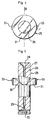
- the injection device shown in FIG. 1 is of the type disposable, that is to say intended to be filled with a liquid to be injected. He is at note that although the injection device as shown does not have protective case to protect the needle without the risk of stinging, after injection, it can be equipped, in a manner known per se, of any protective case of conventional type fulfilling this function.
- This injection device comprises, in the first place, a conventional syringe body having a cylindrical tube 1 having a external collar 2 at one of its ends.
- This syringe body further comprises a mouthpiece 3 adapted to fit conventionally on the end portion of the tube cylindrical 1 opposite the flange 2, and having in a conventional manner a sleeve 4 adapted to engage on said end, and two fins such than 5 digital capture.
- the injection device further comprises a ring 6 adapted to come to cap the end portion of the cylindrical tube 1 opposite to the tip 3.
- This ring 6 consists longitudinally of two cylindrical sleeves 6a, 6b of different external and internal diameters, separated by respectively external 7 and internal 8 shoulders.
- the second sleeve 6b presents as for him, internally, a separate cylindrical bore 10, as mentioned above, of junction section 9d of the first sleeve 6a by the internal shoulder 8.
- This second sleeve 6b is closed, as opposed to the first sleeve 6a, by a front wall 11 pierced with an axial circular orifice 12 of diameter smaller than that of the bore 10.
- This front wall 11 has two indentations 13, 14 diametrically opposite formed on the periphery of the axial orifice 12, and defining with the latter a rectilinear indexing slot of the orientation of the protective cap when mounting the injection device.
- the second sleeve 6b also presents two longitudinal internal grooves 15, 16, diametrically opposed, extending each in line with an indentation 13, 14.
- Each of these grooves 15, 16 of constant width on its greater length has, in addition, a junction end portion 20 with the bore 9 of the first sleeve 6a, of increasing width, so as to form an entrance funnel.
- This second sleeve 6b comprises, finally, projecting by relative to the bottom of each of these grooves 15, 16, a notch such as 17 having a triangular longitudinal section.
- the injection device further comprises means closing the end of the cylindrical tube 1 of the syringe body opposite to the tip 3, adapted to allow to allow the injection of the liquid contained in said tube.
- These sealing means comprise, in the first place, a cylindrical plug 21 adapted to be inserted into the cylindrical tube 1 and provided with a cylindrical flange 22 abutment on the end of said tube.
- This plug 21 is, in addition, pierced with a cylindrical bore through 23 opening into a countersink 24 formed in the front face of said stopper opposite flange 22.
- These sealing means comprise, in addition, an organ shutter and dispenser 25 in the form of a cylindrical barrel of external diameter adapted to be housed in the bore 23 of the plug 21.
- This drum 26 is, moreover, pierced on its greatest length a longitudinal axial bore 27 opening into a countersink 28 formed in one of the end faces of said barrel, said bore being intended in a conventional manner for receive an injection needle 41.
- This closure and dispensing member 25 comprises by elsewhere an intermediate collar 31 consisting of a disc of general shape cylindrical of conjugated diameter of the internal diameter of the bore 10 of the second sleeve 6b of the ring 6.
- This intermediate collar 31 intended to be able to lodge in one or the other chamber 18, 19 of the ring 6, and to be able to move axially in both directions from one to the other of the said chambers, for this purpose two diametrically opposite lugs 32, 33, of longitudinal section substantially triangular conjugate that of the groove sections 15, 16 materializing these chambers 18, 19, and delimited by notches 17.
- this intermediate collar 31 has a upper end face in which are formed two recesses such as 34 concave shape having a longitudinal axis of symmetry, each of said recesses being arranged so that said axis of symmetry is shifted by one angle ⁇ equal to 90 ° with respect to the lugs 32, 33.
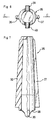
- the injection device comprises; finally, a hood of protection 35 adapted to fit the injection needle 41.
- This protective cap 35 has a general shape frustoconical diameter of base adapted to be able to extend through the axial orifice 12 formed in the end wall 11 of the ring 6.
- This protective cap 35 comprises, in addition, two longitudinal fins 36, 37 diametrically opposed defining a diameter overall maximum of said cap, in the axis of said fins, slightly greater than the diameter separating the bottom of the indentations 13, 14 formed in the front wall of the ring 6.
- These fins 36, 37 are also interrupted remotely of the open bottom end of the protective cap 35, such as represented in FIG. 8, to abut axially on the front wall 11 of the ring 6 once the injection device assembled.
- This protective cap 35 further comprises in the extension of its open end, two ears such as 38 diametrically opposite, in the form of complementary convex undulation concave profiles of the recesses 34 of the intermediate collar 31 of the organ shutter and dispenser 25.
- this protective cap 35 comprises, at the level of each ear 38, an external radial pin 39, 40.
- the protective cap 35 is assembled with the closing and dispensing member 25, so as to bring about cooperation and nest the respective concave and convex profiles of the recesses 34 and ears 38.
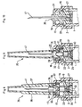
- the plug 21 is then also put in place in the 6, in a position where the flange 22 of said plug is housed in the fourth section 9d of the first sleeve 6a of the ring 6.
- the transverse duct 30 of the barrel 26 of the closure member and distribution 25 is positioned in the bore 23 of said plug, set back compared to the countersink 24 of the latter.
- this cap 21 closes frontally the lower compartment 19 of the ring 6 so as to limit towards the down the axial displacement of the shutter member and distribution 25.
- the last operation is finally to present the body of syringe next to the pre-assembled elements described above, and to grip said syringe body inside the ring 6 to bring the collar 2 of the cylindrical tube 1 to be clipped in the toric intermediate portion 9c of the first sleeve 6a of said ring.
- the protective cap 35 can not be pushed back inside the ring because of the arrangement of the fins 36, 37 positioned in abutment against the front wall 11 of said ring. In addition, this protective cap 35 can not be removed without having undergone the prior to a rotational movement, due to the presence of the radial pins 39, 40.
- the device injection can then be handled, stored, ..., without the risk of liquid or contamination of this liquid.
- the sealing member and dispensing 25 is automatically brought to move axially towards an injection position where on the one hand the intermediate collar 31 is housed in the lower chamber 19 of the ring 6, and secondly, the transverse duct 30 opens into the countersink 24 of the plug 21 allowing the flow and the injection of the liquid.
- the radial pins 39, 40 of the protective cap 35 are automatically brought in line with the notches 13, 14 of the ring 6, allowing the effective removal of said protective cap.
Landscapes
- Health & Medical Sciences (AREA)
- Vascular Medicine (AREA)
- Engineering & Computer Science (AREA)
- Anesthesiology (AREA)
- Biomedical Technology (AREA)
- Heart & Thoracic Surgery (AREA)
- Hematology (AREA)
- Life Sciences & Earth Sciences (AREA)
- Animal Behavior & Ethology (AREA)
- General Health & Medical Sciences (AREA)
- Public Health (AREA)
- Veterinary Medicine (AREA)
- Infusion, Injection, And Reservoir Apparatuses (AREA)
- Medicines That Contain Protein Lipid Enzymes And Other Medicines (AREA)
- Supply Devices, Intensifiers, Converters, And Telemotors (AREA)
- Consolidation Of Soil By Introduction Of Solidifying Substances Into Soil (AREA)
- Injection Moulding Of Plastics Or The Like (AREA)
- Nozzles (AREA)
Applications Claiming Priority (3)
| Application Number | Priority Date | Filing Date | Title |
|---|---|---|---|
| FR9812308A FR2784033B1 (fr) | 1998-10-01 | 1998-10-01 | Dispositif d'injection a usage unique destine a etre pre-rempli |
| FR9812308 | 1998-10-01 | ||
| PCT/FR1999/002325 WO2000020059A1 (fr) | 1998-10-01 | 1999-09-30 | Dispositif d'injection a usage unique destine a etre pre-rempli |
Publications (2)
| Publication Number | Publication Date |
|---|---|
| EP1117454A1 EP1117454A1 (fr) | 2001-07-25 |
| EP1117454B1 true EP1117454B1 (fr) | 2004-11-17 |
Family
ID=9531088
Family Applications (1)
| Application Number | Title | Priority Date | Filing Date |
|---|---|---|---|
| EP99946266A Expired - Lifetime EP1117454B1 (fr) | 1998-10-01 | 1999-09-30 | Dispositif d'injection a usage unique destine a etre pre-rempli |
Country Status (14)
| Country | Link |
|---|---|
| US (1) | US6447480B1 (enExample) |
| EP (1) | EP1117454B1 (enExample) |
| JP (1) | JP4252731B2 (enExample) |
| CN (1) | CN1320053A (enExample) |
| AT (1) | ATE282449T1 (enExample) |
| AU (1) | AU5869299A (enExample) |
| BR (1) | BR9914126A (enExample) |
| CA (1) | CA2345649C (enExample) |
| DE (1) | DE69922034T2 (enExample) |
| ES (1) | ES2234294T3 (enExample) |
| FR (1) | FR2784033B1 (enExample) |
| MX (1) | MXPA01003191A (enExample) |
| PT (1) | PT1117454E (enExample) |
| WO (1) | WO2000020059A1 (enExample) |
Families Citing this family (63)
| Publication number | Priority date | Publication date | Assignee | Title |
|---|---|---|---|---|
| JP4300285B2 (ja) * | 2000-01-07 | 2009-07-22 | グラクソ グループ リミテッド | 液体とりわけ医薬液の一回分用量のための注入装置 |
| FR2839892B1 (fr) * | 2002-05-27 | 2005-03-18 | Mb Innovation | Dispositif d'injection a usage unique destine a etre pre-rempli |
| IL157981A (en) | 2003-09-17 | 2014-01-30 | Elcam Medical Agricultural Cooperative Ass Ltd | Auto injector |
| IL157984A (en) | 2003-09-17 | 2015-02-26 | Dali Medical Devices Ltd | Automatic needle |
| IL160891A0 (en) | 2004-03-16 | 2004-08-31 | Auto-mix needle | |
| GB2414409B (en) | 2004-05-28 | 2009-11-18 | Cilag Ag Int | Injection device |
| GB2414399B (en) | 2004-05-28 | 2008-12-31 | Cilag Ag Int | Injection device |
| GB2414400B (en) * | 2004-05-28 | 2009-01-14 | Cilag Ag Int | Injection device |
| GB2414406B (en) * | 2004-05-28 | 2009-03-18 | Cilag Ag Int | Injection device |
| GB2414402B (en) | 2004-05-28 | 2009-04-22 | Cilag Ag Int | Injection device |
| GB2414775B (en) | 2004-05-28 | 2008-05-21 | Cilag Ag Int | Releasable coupling and injection device |
| GB2414401B (en) | 2004-05-28 | 2009-06-17 | Cilag Ag Int | Injection device |
| GB2414403B (en) | 2004-05-28 | 2009-01-07 | Cilag Ag Int | Injection device |
| GB2425062B (en) | 2005-04-06 | 2010-07-21 | Cilag Ag Int | Injection device |
| GB2427826B (en) | 2005-04-06 | 2010-08-25 | Cilag Ag Int | Injection device comprising a locking mechanism associated with integrally formed biasing means |
| GB2424835B (en) | 2005-04-06 | 2010-06-09 | Cilag Ag Int | Injection device (modified trigger) |
| GB2424838B (en) | 2005-04-06 | 2011-02-23 | Cilag Ag Int | Injection device (adaptable drive) |
| GB2424836B (en) * | 2005-04-06 | 2010-09-22 | Cilag Ag Int | Injection device (bayonet cap removal) |
| EP1754499A1 (en) * | 2005-08-19 | 2007-02-21 | Wei-Shui Wu | Safety hypodermic syringe with retractable needle carrier |
| US7762987B2 (en) * | 2005-08-26 | 2010-07-27 | Wei-Shui Wu | Safety syringe device with separable needle stem by turning back |
| EP1759729B1 (en) | 2005-08-30 | 2009-12-23 | Cilag GmbH International | Needle assembly for a prefilled syringe system |
| US20110098656A1 (en) | 2005-09-27 | 2011-04-28 | Burnell Rosie L | Auto-injection device with needle protecting cap having outer and inner sleeves |
| US20080269692A1 (en) * | 2005-10-11 | 2008-10-30 | Adrian Benton James | Apparatus for Injecting a Pharmaceutical |
| GB2438593B (en) | 2006-06-01 | 2011-03-30 | Cilag Gmbh Int | Injection device (cap removal feature) |
| GB2438590B (en) | 2006-06-01 | 2011-02-09 | Cilag Gmbh Int | Injection device |
| GB2438591B (en) | 2006-06-01 | 2011-07-13 | Cilag Gmbh Int | Injection device |
| ES2679674T3 (es) | 2008-01-11 | 2018-08-30 | Ucb Biopharma Sprl | Sistemas para administrar medicación para pacientes con artritis reumatoide |
| CN101977645B (zh) | 2008-04-10 | 2013-01-30 | 松下电器产业株式会社 | 给药装置 |
| GB2461086B (en) | 2008-06-19 | 2012-12-05 | Cilag Gmbh Int | Injection device |
| GB2461085B (en) | 2008-06-19 | 2012-08-29 | Cilag Gmbh Int | Injection device |
| GB2461084B (en) | 2008-06-19 | 2012-09-26 | Cilag Gmbh Int | Fluid transfer assembly |
| GB2461089B (en) | 2008-06-19 | 2012-09-19 | Cilag Gmbh Int | Injection device |
| GB2461087B (en) | 2008-06-19 | 2012-09-26 | Cilag Gmbh Int | Injection device |
| US8945067B2 (en) | 2008-07-18 | 2015-02-03 | Ucb Pharma, S.A. | Systems for administering medication |
| USD641078S1 (en) | 2008-12-29 | 2011-07-05 | Ucb Pharma, S.A. | Medical syringe with needle tip cap |
| EP2201971A1 (en) * | 2008-12-23 | 2010-06-30 | Sanofi-Aventis Deutschland GmbH | Drug delivery device |
| GB0902354D0 (en) | 2009-02-13 | 2009-04-01 | 3M Innovative Properties Co | Syringes for dispensing multicomponent material |
| IT1399194B1 (it) * | 2010-03-26 | 2013-04-11 | Giuberchio | Dispositivo di protezione a funzionalita' incrementata, particolarmente per siringhe o simili. |
| USD679810S1 (en) | 2011-03-28 | 2013-04-09 | 3M Innovative Properties Company | Dental syringe |
| EP2704524A1 (de) | 2012-08-28 | 2014-03-05 | AEG Power Solutions GmbH | Vorrichtung zum Erwärmen mittels elektromagnetischer Induktion, insbesondere Induktionsheizung oder Induktionsofen |
| EP2911724B1 (en) | 2012-10-25 | 2017-07-19 | Novo Nordisk A/S | A pre-filled disposable injection device |
| GB2515038A (en) | 2013-06-11 | 2014-12-17 | Cilag Gmbh Int | Injection device |
| GB2517896B (en) | 2013-06-11 | 2015-07-08 | Cilag Gmbh Int | Injection device |
| GB2515039B (en) | 2013-06-11 | 2015-05-27 | Cilag Gmbh Int | Injection Device |
| GB2515032A (en) | 2013-06-11 | 2014-12-17 | Cilag Gmbh Int | Guide for an injection device |
| USD792584S1 (en) * | 2014-09-08 | 2017-07-18 | Neomed, Inc. | Male enteral coupling |
| US11376409B2 (en) | 2014-09-08 | 2022-07-05 | Avent, Inc. | Hub component for vented connector |
| USD781417S1 (en) * | 2014-09-08 | 2017-03-14 | Neomed, Inc. | Male enteral coupling |
| CA2959393C (en) | 2014-09-08 | 2020-12-29 | Neomed, Inc. | Vented connector for medical fluid vessels |
| US11357964B2 (en) | 2014-09-08 | 2022-06-14 | Avent, Inc. | Vented connector for medical fluid vessels and tapered plug |
| US10624817B2 (en) | 2015-03-24 | 2020-04-21 | Neomed, Inc. | Oral administration coupler for back-of-mouth delivery |
| USD819198S1 (en) | 2016-04-28 | 2018-05-29 | Amgen Inc. | Autoinjector with removable cap |
| WO2019146330A1 (ja) * | 2018-01-26 | 2019-08-01 | 富士フイルム株式会社 | 内視鏡 |
| USD1010811S1 (en) | 2019-09-30 | 2024-01-09 | Amgen Inc. | Handheld drug delivery device |
| USD1030041S1 (en) | 2020-01-14 | 2024-06-04 | Amgen Inc. | Handheld drug delivery device |
| USD1030040S1 (en) | 2020-01-14 | 2024-06-04 | Amgen Inc. | Handheld drug delivery device |
| USD962423S1 (en) | 2020-11-05 | 2022-08-30 | Amgen Inc. | Handheld drug delivery device |
| USD973866S1 (en) | 2020-11-05 | 2022-12-27 | Amgen Inc. | Handheld drug delivery device |
| USD974547S1 (en) | 2020-11-05 | 2023-01-03 | Amgen Inc. | Handheld drug delivery device |
| USD985118S1 (en) | 2021-03-10 | 2023-05-02 | Amgen Inc. | Handheld drug delivery device |
| USD985117S1 (en) | 2021-03-10 | 2023-05-02 | Amgen Inc. | Handheld drug delivery device |
| USD985116S1 (en) | 2021-03-10 | 2023-05-02 | Amgen Inc. | Handheld drug delivery device |
| USD985119S1 (en) | 2021-03-30 | 2023-05-02 | Amgen Inc. | Handheld drug delivery device |
Family Cites Families (18)
| Publication number | Priority date | Publication date | Assignee | Title |
|---|---|---|---|---|
| DE847473C (de) | 1944-04-07 | 1952-08-25 | Albert Heinrich Dr Med Bertram | Ampullenspritze |
| DE2008751A1 (de) | 1964-08-11 | 1971-09-09 | Buender Glas Gmbh | Zylindrische Spritzampulle mit Injektionskanuele |
| DE1909794A1 (de) | 1969-02-27 | 1970-09-17 | Ehrhardt Soehne Fa | Spritzampulle fuer zwei Komponenten |
| FR2208684A1 (en) | 1972-12-05 | 1974-06-28 | Mpl Inc | Pre-filled glass-plastic syringe with ejectable plug - suitable for prolonged storage of contents prior to use |
| DE2315367A1 (de) * | 1973-03-28 | 1974-10-17 | Hoechst Ag | Injektionsspritze zur einmaligen verwendung |
| FR2330413A1 (fr) | 1975-11-06 | 1977-06-03 | Sauzin Sa Ets | Canule pour injections |
| US4051850A (en) | 1975-11-21 | 1977-10-04 | Tischlinger Edward A | Disposable medicament injector |
| NL180634C (nl) | 1977-12-23 | 1987-04-01 | Duphar Int Res | Injectiespuit alsmede naaldhouder hiervoor. |
| EP0111796B1 (fr) | 1982-12-20 | 1986-05-28 | Medicorp Holding S.A. | Ampoule-seringue |
| EP0146558B1 (fr) | 1983-05-04 | 1988-08-24 | Medicorp Holding S.A. | Seringue preremplie a dose unitaire |
| DE3468174D1 (en) | 1984-01-25 | 1988-02-04 | Medicorp Holding | Pre-filled syringe for unitary dose |
| EP0175775A1 (en) * | 1984-04-04 | 1986-04-02 | Sigma Company Limited | Syringes |
| ATE42041T1 (de) | 1985-02-07 | 1989-04-15 | Duphar Int Res | Injektionsspritze. |
| US4639250A (en) | 1986-02-20 | 1987-01-27 | Becton, Dickinson And Company | Syringe barrel and hypodermic needle assembly |
| US5308330A (en) | 1992-09-16 | 1994-05-03 | Becton, Dickinson And Company | Syringe having needle isolation features |
| US5250037A (en) | 1992-12-18 | 1993-10-05 | Becton, Dickinson And Company | Syringe having needle isolation features |
| NL9401173A (nl) * | 1994-07-15 | 1996-02-01 | A P I S Medical Bv | Voorgevuld injektiespuitsamenstel. |
| JP3208525B2 (ja) | 1995-01-05 | 2001-09-17 | 電気化学工業株式会社 | ヒアルロン酸ナトリウム溶液注射剤および注射用容器 |
-
1998
- 1998-10-01 FR FR9812308A patent/FR2784033B1/fr not_active Expired - Lifetime
-
1999
- 1999-09-30 CA CA002345649A patent/CA2345649C/fr not_active Expired - Lifetime
- 1999-09-30 WO PCT/FR1999/002325 patent/WO2000020059A1/fr not_active Ceased
- 1999-09-30 PT PT99946266T patent/PT1117454E/pt unknown
- 1999-09-30 AU AU58692/99A patent/AU5869299A/en not_active Abandoned
- 1999-09-30 EP EP99946266A patent/EP1117454B1/fr not_active Expired - Lifetime
- 1999-09-30 ES ES99946266T patent/ES2234294T3/es not_active Expired - Lifetime
- 1999-09-30 US US09/806,574 patent/US6447480B1/en not_active Expired - Lifetime
- 1999-09-30 AT AT99946266T patent/ATE282449T1/de active
- 1999-09-30 BR BR9914126-4A patent/BR9914126A/pt not_active IP Right Cessation
- 1999-09-30 JP JP2000573416A patent/JP4252731B2/ja not_active Expired - Lifetime
- 1999-09-30 MX MXPA01003191A patent/MXPA01003191A/es active IP Right Grant
- 1999-09-30 CN CN99811555A patent/CN1320053A/zh active Pending
- 1999-09-30 DE DE69922034T patent/DE69922034T2/de not_active Expired - Lifetime
Also Published As
| Publication number | Publication date |
|---|---|
| JP4252731B2 (ja) | 2009-04-08 |
| BR9914126A (pt) | 2001-06-19 |
| CA2345649C (fr) | 2008-11-25 |
| ES2234294T3 (es) | 2005-06-16 |
| EP1117454A1 (fr) | 2001-07-25 |
| WO2000020059A1 (fr) | 2000-04-13 |
| CA2345649A1 (fr) | 2000-04-13 |
| AU5869299A (en) | 2000-04-26 |
| MXPA01003191A (es) | 2002-07-02 |
| ATE282449T1 (de) | 2004-12-15 |
| FR2784033A1 (fr) | 2000-04-07 |
| DE69922034T2 (de) | 2005-12-08 |
| DE69922034D1 (de) | 2004-12-23 |
| CN1320053A (zh) | 2001-10-31 |
| FR2784033B1 (fr) | 2000-12-22 |
| US6447480B1 (en) | 2002-09-10 |
| PT1117454E (pt) | 2005-04-29 |
| JP2002526175A (ja) | 2002-08-20 |
Similar Documents
| Publication | Publication Date | Title |
|---|---|---|
| EP1117454B1 (fr) | Dispositif d'injection a usage unique destine a etre pre-rempli | |
| EP1117453B1 (fr) | Dispositif d'injection a usage unique destine a etre pre-rempli | |
| EP0336855B1 (fr) | Seringue à usage unique | |
| EP1663102B1 (fr) | Dispositif d'administration orale d'un medicament | |
| EP1218047B1 (fr) | Dispositif d'injection a usage unique | |
| EP1257308B1 (fr) | Dispositif d'injection d'une dose de liquide notamment medicamenteux | |
| EP0393166B1 (fr) | Seringue du type comportant une aiguille d'injection a usage unique, notamment pour le domaine dentaire | |
| EP0732114B1 (fr) | Dispositif de perforation et ensemble de raccordement pour système d'alimentation par voie entérale et procédé de raccordement | |
| EP1507565B1 (fr) | Dispositif d injection a usage unique destine a etre pre-rem pli | |
| CA2837816A1 (fr) | Dispositif de connexion entre un recipient et un contenant, procede d'assemblage et d'utilisation d'un tel dispositif | |
| CA2908800C (fr) | Flacon de conditionnement de liquide | |
| CA2875492A1 (fr) | Ensemble d'injection | |
| EP1345566B1 (fr) | Dispositif de reconstitution notamment pour le mélange de substances dans le domaine médical | |
| EP3352821B1 (fr) | Ensemble de distribution comportant une seringue et un dispositif de protection pour aiguille | |
| EP3383342B1 (fr) | Dispositif de connexion entre un récipient et un contenant et ensemble de connexion comprenant un tel dispositif | |
| FR2803530A1 (fr) | Dispositif d'injection d'une dose de liquide notamment medicamenteux | |
| FR2620942A1 (fr) | Embout d'injection pour seringue, notamment du type a usage unique pour le domaine dentaire | |
| FR3019804A1 (fr) | Flacon de conditionnement de liquide | |
| FR2650350A1 (fr) | Systeme de fixation d'un dispositif tel qu'un ecrou ou ensemble a ecrou sur un organe de support |
Legal Events
| Date | Code | Title | Description |
|---|---|---|---|
| PUAI | Public reference made under article 153(3) epc to a published international application that has entered the european phase |
Free format text: ORIGINAL CODE: 0009012 |
|
| 17P | Request for examination filed |
Effective date: 20010313 |
|
| AK | Designated contracting states |
Kind code of ref document: A1 Designated state(s): AT BE CH CY DE DK ES FI FR GB GR IE IT LI LU MC NL PT SE |
|
| AX | Request for extension of the european patent |
Free format text: AL;LT;LV;MK;RO;SI |
|
| 17Q | First examination report despatched |
Effective date: 20030205 |
|
| GRAP | Despatch of communication of intention to grant a patent |
Free format text: ORIGINAL CODE: EPIDOSNIGR1 |
|
| GRAS | Grant fee paid |
Free format text: ORIGINAL CODE: EPIDOSNIGR3 |
|
| GRAA | (expected) grant |
Free format text: ORIGINAL CODE: 0009210 |
|
| RAP1 | Party data changed (applicant data changed or rights of an application transferred) |
Owner name: SANOFI-AVENTIS |
|
| AK | Designated contracting states |
Kind code of ref document: B1 Designated state(s): AT BE CH CY DE DK ES FI FR GB GR IE IT LI LU MC NL PT SE |
|
| REG | Reference to a national code |
Ref country code: GB Ref legal event code: FG4D Free format text: NOT ENGLISH |
|
| REG | Reference to a national code |
Ref country code: CH Ref legal event code: EP |
|
| REG | Reference to a national code |
Ref country code: IE Ref legal event code: FG4D Free format text: FRENCH |
|
| REF | Corresponds to: |
Ref document number: 69922034 Country of ref document: DE Date of ref document: 20041223 Kind code of ref document: P |
|
| REG | Reference to a national code |
Ref country code: CH Ref legal event code: NV Representative=s name: BOVARD AG PATENTANWAELTE |
|
| REG | Reference to a national code |
Ref country code: SE Ref legal event code: TRGR |
|
| REG | Reference to a national code |
Ref country code: DK Ref legal event code: T3 |
|
| REG | Reference to a national code |
Ref country code: GR Ref legal event code: EP Ref document number: 20050400538 Country of ref document: GR |
|
| GBT | Gb: translation of ep patent filed (gb section 77(6)(a)/1977) |
Effective date: 20050316 |
|
| REG | Reference to a national code |
Ref country code: PT Ref legal event code: SC4A Free format text: AVAILABILITY OF NATIONAL TRANSLATION Effective date: 20050211 |
|
| REG | Reference to a national code |
Ref country code: ES Ref legal event code: FG2A Ref document number: 2234294 Country of ref document: ES Kind code of ref document: T3 |
|
| PLBE | No opposition filed within time limit |
Free format text: ORIGINAL CODE: 0009261 |
|
| STAA | Information on the status of an ep patent application or granted ep patent |
Free format text: STATUS: NO OPPOSITION FILED WITHIN TIME LIMIT |
|
| 26N | No opposition filed |
Effective date: 20050818 |
|
| REG | Reference to a national code |
Ref country code: CH Ref legal event code: PFA Owner name: SANOFI-AVENTIS Free format text: SANOFI-AVENTIS#174, AVENUE DE FRANCE#75013 PARIS (FR) -TRANSFER TO- SANOFI-AVENTIS#174, AVENUE DE FRANCE#75013 PARIS (FR) |
|
| REG | Reference to a national code |
Ref country code: DE Ref legal event code: R082 Ref document number: 69922034 Country of ref document: DE Representative=s name: DR. WEITZEL & PARTNER, DE |
|
| REG | Reference to a national code |
Ref country code: DE Ref legal event code: R082 Ref document number: 69922034 Country of ref document: DE Representative=s name: DR. WEITZEL & PARTNER PATENT- UND RECHTSANWAEL, DE Effective date: 20130205 Ref country code: DE Ref legal event code: R082 Ref document number: 69922034 Country of ref document: DE Representative=s name: DR. WEITZEL & PARTNER, DE Effective date: 20130205 Ref country code: DE Ref legal event code: R081 Ref document number: 69922034 Country of ref document: DE Owner name: SANOFI-AVENTIS, FR Free format text: FORMER OWNER: SANOFI-AVENTIS, PARIS, FR Effective date: 20130205 Ref country code: DE Ref legal event code: R081 Ref document number: 69922034 Country of ref document: DE Owner name: SANOFI, FR Free format text: FORMER OWNER: SANOFI-AVENTIS, PARIS, FR Effective date: 20130205 |
|
| REG | Reference to a national code |
Ref country code: FR Ref legal event code: PLFP Year of fee payment: 18 |
|
| REG | Reference to a national code |
Ref country code: FR Ref legal event code: PLFP Year of fee payment: 19 |
|
| REG | Reference to a national code |
Ref country code: DE Ref legal event code: R082 Ref document number: 69922034 Country of ref document: DE Representative=s name: DR. WEITZEL & PARTNER PATENT- UND RECHTSANWAEL, DE Ref country code: DE Ref legal event code: R081 Ref document number: 69922034 Country of ref document: DE Owner name: SANOFI, FR Free format text: FORMER OWNER: SANOFI-AVENTIS, 75013 PARIS, FR |
|
| REG | Reference to a national code |
Ref country code: FR Ref legal event code: PLFP Year of fee payment: 20 |
|
| PGFP | Annual fee paid to national office [announced via postgrant information from national office to epo] |
Ref country code: MC Payment date: 20180829 Year of fee payment: 20 Ref country code: FR Payment date: 20180813 Year of fee payment: 20 Ref country code: LU Payment date: 20180910 Year of fee payment: 20 Ref country code: IT Payment date: 20180919 Year of fee payment: 20 Ref country code: IE Payment date: 20180911 Year of fee payment: 20 Ref country code: DE Payment date: 20180918 Year of fee payment: 20 |
|
| PGFP | Annual fee paid to national office [announced via postgrant information from national office to epo] |
Ref country code: DK Payment date: 20180911 Year of fee payment: 20 Ref country code: GR Payment date: 20180810 Year of fee payment: 20 Ref country code: FI Payment date: 20180910 Year of fee payment: 20 Ref country code: SE Payment date: 20180910 Year of fee payment: 20 Ref country code: AT Payment date: 20180828 Year of fee payment: 20 Ref country code: NL Payment date: 20180912 Year of fee payment: 20 Ref country code: CH Payment date: 20180913 Year of fee payment: 20 Ref country code: BE Payment date: 20180717 Year of fee payment: 20 Ref country code: GB Payment date: 20180926 Year of fee payment: 20 |
|
| PGFP | Annual fee paid to national office [announced via postgrant information from national office to epo] |
Ref country code: PT Payment date: 20180925 Year of fee payment: 20 |
|
| PGFP | Annual fee paid to national office [announced via postgrant information from national office to epo] |
Ref country code: ES Payment date: 20181001 Year of fee payment: 20 |
|
| PGFP | Annual fee paid to national office [announced via postgrant information from national office to epo] |
Ref country code: CY Payment date: 20180928 Year of fee payment: 20 |
|
| REG | Reference to a national code |
Ref country code: DE Ref legal event code: R071 Ref document number: 69922034 Country of ref document: DE |
|
| REG | Reference to a national code |
Ref country code: NL Ref legal event code: MK Effective date: 20190929 |
|
| REG | Reference to a national code |
Ref country code: DK Ref legal event code: EUP Effective date: 20190930 |
|
| REG | Reference to a national code |
Ref country code: CH Ref legal event code: PL |
|
| REG | Reference to a national code |
Ref country code: GB Ref legal event code: PE20 Expiry date: 20190929 |
|
| REG | Reference to a national code |
Ref country code: IE Ref legal event code: MK9A |
|
| REG | Reference to a national code |
Ref country code: BE Ref legal event code: MK Effective date: 20190930 |
|
| REG | Reference to a national code |
Ref country code: AT Ref legal event code: MK07 Ref document number: 282449 Country of ref document: AT Kind code of ref document: T Effective date: 20190930 |
|
| REG | Reference to a national code |
Ref country code: SE Ref legal event code: EUG |
|
| PG25 | Lapsed in a contracting state [announced via postgrant information from national office to epo] |
Ref country code: GB Free format text: LAPSE BECAUSE OF EXPIRATION OF PROTECTION Effective date: 20190929 |
|
| PG25 | Lapsed in a contracting state [announced via postgrant information from national office to epo] |
Ref country code: PT Free format text: LAPSE BECAUSE OF EXPIRATION OF PROTECTION Effective date: 20191010 Ref country code: IE Free format text: LAPSE BECAUSE OF EXPIRATION OF PROTECTION Effective date: 20190930 |
|
| REG | Reference to a national code |
Ref country code: ES Ref legal event code: FD2A Effective date: 20200805 |
|
| PG25 | Lapsed in a contracting state [announced via postgrant information from national office to epo] |
Ref country code: ES Free format text: LAPSE BECAUSE OF EXPIRATION OF PROTECTION Effective date: 20191001 |