EP1117111A1 - Mit einem Gelenkparallelogramm versehene Antriebseinrichtung für ein Kontaktorgan eines elektrischen Schalters - Google Patents
Mit einem Gelenkparallelogramm versehene Antriebseinrichtung für ein Kontaktorgan eines elektrischen Schalters Download PDFInfo
- Publication number
- EP1117111A1 EP1117111A1 EP00410150A EP00410150A EP1117111A1 EP 1117111 A1 EP1117111 A1 EP 1117111A1 EP 00410150 A EP00410150 A EP 00410150A EP 00410150 A EP00410150 A EP 00410150A EP 1117111 A1 EP1117111 A1 EP 1117111A1
- Authority
- EP
- European Patent Office
- Prior art keywords
- lever
- parallelogram
- closing
- drive member
- axis
- Prior art date
- Legal status (The legal status is an assumption and is not a legal conclusion. Google has not performed a legal analysis and makes no representation as to the accuracy of the status listed.)
- Granted
Links
Images


Classifications
-
- H—ELECTRICITY
- H01—ELECTRIC ELEMENTS
- H01H—ELECTRIC SWITCHES; RELAYS; SELECTORS; EMERGENCY PROTECTIVE DEVICES
- H01H3/00—Mechanisms for operating contacts
- H01H3/22—Power arrangements internal to the switch for operating the driving mechanism
- H01H3/30—Power arrangements internal to the switch for operating the driving mechanism using spring motor
- H01H3/3047—Power arrangements internal to the switch for operating the driving mechanism using spring motor adapted for operation of a three-position switch, e.g. on-off-earth
-
- H—ELECTRICITY
- H01—ELECTRIC ELEMENTS
- H01H—ELECTRIC SWITCHES; RELAYS; SELECTORS; EMERGENCY PROTECTIVE DEVICES
- H01H3/00—Mechanisms for operating contacts
- H01H3/32—Driving mechanisms, i.e. for transmitting driving force to the contacts
- H01H3/46—Driving mechanisms, i.e. for transmitting driving force to the contacts using rod or lever linkage, e.g. toggle
Definitions
- the invention relates to a drive mechanism of a movable contact member of a switchgear.
- Patent application FR-A-2 681 723 describes a mechanism with two parallelograms allowing the control of a vacuum bulb, driven by a spring.
- the mechanism described does not allows only very small angular displacements of the two parallelograms, which only slightly deform between the open position and the closed position of the mechanism. Therefore, the effort transmission ratio of the mechanism is almost constant.
- the force applied by the mechanism at the stem of the bulb is in an almost constant relationship with the force applied by the spring.
- the force applied by the spring to the mechanism decreases during the expansion in proportion to the elongation of the spring, the force applied by the mechanism at the stem of the bulb therefore also decreases during movement closing.
- An object of the present invention is to provide a drive mechanism for a switchgear such as a vacuum interrupter, which does not have the drawbacks identified above, and in particular ensures a significant effort transmission report at the end of the closing stroke, so that the residual force of the closing spring partially unloaded at the end of the closing stroke is sufficient to ensure the contact pressure.
- the decrease in the force applied by the spring and due to the partial relaxation of at closing is this at least partially offset by the increase of the transmission report.
- the increase in the transmission ratio is continuous between the separation position and the contact position.
- transmission relationships discussed in this talk are static transmission ratios, such as can be measured when the parts in play are immobile. More specifically, the transmission ratios considered can be measured in each position of the mechanism, immobilizing the contact member or the drive member in the selected position. This is what the expression "in the absence of movement "used previously.
- This increase contributes at least partially to the increase in the overall transmission ratio ⁇ .
- the first lever comprises a member for connection to the closing spring
- the second lever comprises a connecting member to a closing latch capable of preventing movement of the parallelogram from its position opening to its closed position.
- the first lever comprises a member for connection to the closing spring
- the second lever comprises a member for connecting to means for applying an opening driving force.
- the transmission means comprise means for guiding the drive member with respect to the chassis, leaving the member drive at least one degree of freedom of translation relative to the chassis.
- the transmission means comprise means for guiding the drive member with respect to the transmission rod leaving the drive member at least a degree of freedom of translation relative to the connecting rod.
- the angle of rotation of the first and second levers between the open position and the closed position is important.
- the mechanism of the invention is thus compatible with a closed / open control and allows to easily dimension the closing spring independently of each other and the opening spring.
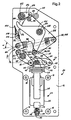
- a three-pole vacuum circuit breaker 10 includes a frame constituted by parallel flanges 14 fixed to each other and held in position by spacers 16, 18.
- the flanges 14 separate three pole compartments 20.
- Each polar compartment receives a vacuum interrupter 22 comprising a fixed contact 24 integral with an insulating envelope 26, and a movable contact 28.
- a material support axis 30 of the fixed contact 24 is pivotally mounted relative to the two flanges 14 delimiting the compartment.
- This support 30 comprises a bore 32 for guiding in translation for a rod 34 at the end of the fixed contact.
- a contact pressure spring 36 with a flange is disposed between the support 30 and the body of the envelope.
- the movable contact 28 comprises a rod whose head 40 comes out of the envelope and forms a stirrup.
- the movable contact defines a longitudinal geometric axis which, when the contact mobile is centered relative to the envelope and located in the extension of the fixed contact, coincides with the radial geometric axis of translation of the envelope defined by the bore 32.
- the stirrup 40 has two cheeks 44 each provided with a bore.
- An axis 46 is arranged transversely in the stirrup and passes through the bores of the cheeks 44.
- the axis 46 supports a central roller 48 located between the cheeks 44 and two lateral rollers 50 at its ends outside cheeks 44.
- the two flanges 14 framing each pole have two oblong holes 52 similar located one opposite the other.
- Each oblong hole 52 defines an axis longitudinal which is arranged radially with respect to the geometric pivot axis of the support 30 of the casing 26.
- the longitudinal axis of the oblong 52 intersects the geometric pivot axis of the support 30 and is perpendicular thereto.
- the pebbles lateral 50 of axis 46 each cooperate with the oblong hole 52 made in the flange 14 corresponding to the chassis 12, so that the stirrup 40 is free to move in translation relative to the flanges 14 parallel to the longitudinal axes of the oblongs, and pivot around the rollers 50.
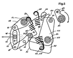
- the mechanism for driving the mobile contact comprises a lower stage, a stage upper and a control stage.
- the lower stage comprises a switching bar 53 common to the three poles, consisting of a hexagonal shaft mounted in bearings supported by the flanges 14.
- Each polar compartment 20 comprises an articulated parallelogram 56 consisting of a crank lever 58 integral with the switching rod 53, a control lever 60 pivoting about an axis 62 supported by the flanges 14 and a transmission rod 64.
- the crank lever 58 consists of two identical and parallel flat parts located on either side of the transmission rod 64 and connected to it by through a pivot axis 66, so as to avoid overhangs.
- the control lever 60 consists of two identical and parallel flat parts located on either side of the transmission rod 64 and connected to it by through a pivot axis 68.
- the connecting rod 64 is provided with an oblong slot 70 whose longitudinal geometric axis is perpendicular to that of the oblong holes of the flanges 14 and intersects the geometric axis of axis 66 and that of axis 68. Axes 66, 68, 62 and the shaft 53 are all parallel to each other and perpendicular to the flanges 14. The connecting rod 64 is thus able to move parallel to itself when the bar of switching 53 pivots.
- the central roller 48 of the axis 46 cooperates with the oblong light 70 of the connecting rod 64.
- the axis 46 cooperates both with the oblong lumen 70 and with the oblong holes 52, so that its position is always determined by the position of the intersection between the oblong holes 52 and the oblong lumen 70.
- the crank lever 58 is provided with a pin 72.
- the control lever 60 is provided an axis 74 on which two coaxial rollers are mounted: a central roller 76, called a roller opening, located between the two flat parts of the control lever, and a side roller 77, said closing roller, located outside one of the side flat parts of the lever 60.
- the upper stage of the mechanism has two hexagonal shafts common to the three poles and mounted pivoting with respect to the flanges, namely: a camshaft 80 and a armament tree 82.
- the cocking shaft 82 is provided, for each pole, with a cocking crank 84 supporting an arming cam 83 and a percussion pin 85.
- the arming shaft 82 is rotated by drive means not shown, for example a motor and / or by hand-operated pump handle.
- the coupling between the arming shaft 82 and the drive means comprises a free wheel (not shown) which couples the drive means to the shaft when the means drive transmit clockwise motor torque to the shaft, and otherwise disengage the drive means.
- the armament tree 82 is also provided with a second freewheel (not shown) relative to one of the flanges 14, which prohibits the rotation of the shaft 82 anti-clockwise and authorizes rotating the shaft clockwise.
- the camshaft 80 is provided with three identical multifunctional cams 88, one per pole 20.
- Each multifunction cam 88 has a first concave active surface 90 capable of cooperate with the opening roller 76, as well as a second active staircase surface consisting of an area in an arc 92 centered on the geometric axis of the tree and a locking stop 94.
- Each cam 88 also includes a roller 96 intended to cooperate with the cam 83 of the cocking crank 84.
- the multi-function cam of the pole central is recalled clockwise in the figures by an opening spring 98 fixed to a pin 100 held in one of the lateral flanges and to a pin 102 fixed to the cam and off-center with respect to its axis of rotation 80.
- the multifunction cams of both side poles are each provided with a closing spring 106, one end of which is hooked to the cam 88 by means of a pin 108 coaxial with the ankles 102 lateral multifunction cams, the other end of which is attached to the ankle 72 of the crank lever 58.
- a closing spring 106 one end of which is hooked to the cam 88 by means of a pin 108 coaxial with the ankles 102 lateral multifunction cams, the other end of which is attached to the ankle 72 of the crank lever 58.
- the opening 98 and closing 106 springs are tension springs, i.e. springs whose potential energy increases when are stretched.
- the movement of the cams 88 is limited clockwise by a stop of limit switch 110.
- the control stage is located between the flanges of the central pole. It brings together a open command and a close command.
- the opening command comprises, between the flanges of the central pole, a latch aperture 116 in half-moon shaped on a rotary axis 118 supported by bearings mounted on the flanges of the central pole.
- This lock is intended to cooperate with the second active surface of the multi-function cam 88 of the central pole. It is recalled in the sense counterclockwise in the figures by a return spring 120. From known manner and not shown, the lock 116 is connected to a release member allowing it to be triggered manually or on electrical fault.
- the closing command comprises, for each pole 20, the percussion plug 85 as well as a closing lock 126 constituted by a lever mounted idly on a bearing 128 carried by the hexagonal shaft 80.
- the closing lock 126 is returned clockwise in Figures 2 to 5 by a return spring not shown.
- Lock 126 has a arm defining a range 130 cooperating with the pin 85 and a second arm defining a curved surface and a rest surface, these two surfaces being intended to cooperate with the closing roller 77 of the control lever 60.
- the movement of the lock 126 clockwise is limited by a stop not shown.
- the end position clockwise stroke is a so-called locking position, shown on the figure 2.
- the circuit breaker 10 in its disarmed open state is shown in FIG. 2.
- the closing latch 126 In this position, the closing latch 126 is in its locking position, at the end stop running clockwise.
- the closing roller 77 bears on the curved surface of the lock 126 so that the moment, relative to the axis of rotation of lock 126, of the force applied by the roller 77 on the lock 126, tends to rotate the latter in the clockwise.
- the position of the lock 126 is therefore stable. Lock 126 prevents rotation of the control lever 60 clockwise.
- the opening spring 98 and the closing springs 106 are very weakly bandaged and recall the multifunction cams 88 and with them the camshaft 80, in the direction clockwise, the concave surface 90 being in contact with the opening roller 76.
- the spring of closure 106 also tends to rotate the crank lever 58 clockwise, but this movement is blocked due to the interaction between the control lever 60 and the closing lock 126.
- the transmission rod 64 is in a high position and maintains the pin 46, the caliper 40 and the movable contact 28 in an open position of separation.
- the opening lock 116 rests on the circular arc 92.
- the arming of the mechanism is produced by the rotation of the arming shaft 82 in the clockwise.
- the arming cam 84 comes into contact with the arming roller 96 and drives the multifunction cams 88 and the camshaft 80 in the opposite direction to Clockwise.
- the closing latch 126 prevents any rotation of the lever control 60 clockwise, so that the parallelogram 56 remains in its open position.
- Closing spring 106 and opening springs 98 are bandaged due to the rotation of the pins 108 and 102 which move away from the pins 72 and 100.
- the camshaft 80 reaches an extreme position shown in FIG. 3, when the cocking cam 84 and cocking roller 96 reach a respective point position dead. In this position, the opening latch 116 has been released by the cam 92, so that the lock 116 has pivoted in the locked position under the action of its spring reminder 120.
- the camshaft 80 ceases to be a receiver and becomes a motor, under the effect of the closing springs 106 and 98.
- the multifunction cam 88 pivots under the stress of the springs opening 98 and closing 106, until meeting the opening lock 116.
- the movement of the arming roller 96 is transmitted to the cam 84 and the shaft 82 is pivoted clockwise.
- the ankle 85 then strikes the scope 130 of the locking latch 126 and drives the latter in an anticlockwise direction of a watch, as shown in FIG. 4.
- the closing lock 126 then releases the roller 77 of the control lever 60, so that the parallelogram 56 is deformed by pivoting of the control lever 60 and the crank lever 58 clockwise under the bias of the closing spring 106, the multifunction cam 88 remaining blocked clockwise through the opening lock 116.
- the transmission rod 64 moves while remaining perpendicular to the oblong holes 52. It drives the axis 46, the stirrup 40 of which it is integral and the movable contact 28 integral with the stirrup until a closed contact position shown in Figure 5, in which the movable contact 28 is in contact with the fixed contact 24 and the contact pressure spring 36 is compressed about halfway.
- the control roller 74 maintains the closing latch 126 against the force of the latch return spring 126.
- the locking spring closure 106 is partially disbanded, due to the mutual closeness of the ankles 72 and 108.
- the opening springs 98 of the side poles remain bandaged, from the makes the ankles 100 immobile with respect to the ankles 102.
- the direction of the result of the forces applied by the closing spring 106 on the parallelogram 56 is defined by the geometric axis of the closing spring 106 which passes through the pin 72 and the pin 108 and is parallel to the plan of Figures 2 to 5, the point of application of the result of the forces applied by the closing spring 106 on the parallelogram 56 is located on the pin 72.
- the upstream static transmission ratio defined by the ratio: ⁇ 0 C 0 / R, where R is the modulus of the result of the forces transmitted by the closing spring 106 in the parallelogram 56 and C 0 is the absolute value of the moment with respect to the geometric axis of the shaft 53 of the result of the forces transmitted by the spring 106 to the parallelogram 56, increases in value r absolute, so that the ratio ⁇ 0 is higher at the end of the closing stroke than at the beginning.
- the direction of the forces transmitted by the transmission rod 64 to the axis 46 integral with the stirrup 40 during closing is essentially perpendicular to the longitudinal axis of the oblong lumen 70 and parallel to the longitudinal axis of the holes. oblong 52.
- the opening of the circuit breaker 10 is initiated by the rotation of the opening latch 116, in response to a manual or automatic trigger order.
- the pivoting of the half-moon 116 releases the multifunction cam 88 from the central pole, and with it the camshaft 80.
- the multifunction cam 88 and the camshaft 80 rotate clockwise.
- the concave surface 90 of the multifunction cam 88 enters in contact with the opening roller 76 and pivots the control lever 60 in the clockwise, causing the parallelogram 56 to fold back.
- the transmission rod 64 drives the axis 46 in translation in the direction of opening.
- the circuit breaker is then returned to the position shown in Figure 2.
- the invention is not limited to the embodiment described above. In particular, it applies as well to a three-phase apparatus as to an apparatus single phase. Various variants are possible.
- the figure shows a second embodiment of the invention, which does not differ from the first mode only by the shape of the light 270 of the transmission rod.
- the form selected curve allows to influence the transmission ratio during the closing and opening.
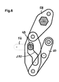
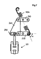
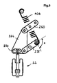
- FIG. 7 and 8 schematically represent a variant according to a third embodiment of the invention, comprising a vacuum interrupter 222 and a parallelogram mechanism comprising a crank lever 258, a control lever 260 and a transmission rod 264 provided of a light 270.
- This variant differs from the first embodiment in that the axis of the connecting rod 264, that is to say the geometric axis perpendicular and intersecting with the two pivot axes of the connecting rod 264, is parallel to the axis of the vacuum interrupter 222.
- the lever arm of the closing spring is relatively small due to its angle of inclination ⁇ relative to the crank lever, while its tension is maximum.
- the angle of inclination ⁇ of the spring relative to the crank lever approaches the right angle so that the transmission ratio ⁇ 1 increases.
- the ratio ⁇ 2 also increases, so that in this embodiment also the overall transmission ratio ⁇ increases.
- FIG. 9 represents a variant according to a fourth embodiment of the invention which makes it possible to control the opening and the closing of a circuit breaker, the movable contact member 328 of which includes contact 328a mounted pivoting with respect to an axis 328b fixed to a support 328c which pivots itself relative to an axis 328d fixed to the chassis of the mechanism.
- a contact spring 336 provides contact pressure in the closed position.
- the drive mechanism, and in particular the parallelogram 356, is similar to that of the first embodiment. The connection between the parallelogram 356 and the contact member 328 is ensured by a link 346.
- control of the mechanism can make calls for a separation between arming and initiating closure. It is enough for this that the closing pin 85 is omitted on the cocking shaft, and that a independent means is used to rotate the closing latch.
- the opening spring (s) can either be placed on the central pole and / or on the side poles. The same applies to the closing spring or springs.
- Ankles 102 and 108 are not necessarily coaxial. Close command is not necessarily duplicated on each of the poles.
- the opening command can be arranged on a side pole. It can also be duplicated on each of the poles.
Applications Claiming Priority (2)
| Application Number | Priority Date | Filing Date | Title |
|---|---|---|---|
| FR0000229 | 2000-01-10 | ||
| FR0000229A FR2803685B1 (fr) | 2000-01-10 | 2000-01-10 | Mecanisme a parallelogramme articule pour l'entrainement d'un organe de contact d'un appareil electrique de coupure |
Publications (2)
| Publication Number | Publication Date |
|---|---|
| EP1117111A1 true EP1117111A1 (de) | 2001-07-18 |
| EP1117111B1 EP1117111B1 (de) | 2006-07-26 |
Family
ID=8845735
Family Applications (1)
| Application Number | Title | Priority Date | Filing Date |
|---|---|---|---|
| EP20000410150 Expired - Lifetime EP1117111B1 (de) | 2000-01-10 | 2000-12-07 | Mit einem Gelenkparallelogramm versehene Antriebseinrichtung für ein Kontaktorgan eines elektrischen Schalters |
Country Status (4)
| Country | Link |
|---|---|
| EP (1) | EP1117111B1 (de) |
| DE (1) | DE60029555T2 (de) |
| ES (1) | ES2265900T3 (de) |
| FR (1) | FR2803685B1 (de) |
Cited By (2)
| Publication number | Priority date | Publication date | Assignee | Title |
|---|---|---|---|---|
| CN102184799A (zh) * | 2011-01-07 | 2011-09-14 | 无锡市锡山湖光电器有限公司 | 真空馈电开关的手动分闸自动复位装置 |
| CN105742087A (zh) * | 2016-04-26 | 2016-07-06 | 亚洲电力设备(深圳)股份有限公司 | 一种大电流隔离开关 |
Families Citing this family (1)
| Publication number | Priority date | Publication date | Assignee | Title |
|---|---|---|---|---|
| DE102020203288A1 (de) | 2020-03-13 | 2021-09-16 | Siemens Aktiengesellschaft | Stromunterbrechervorrichtung mit mehreren Schalteinheiten |
Citations (2)
| Publication number | Priority date | Publication date | Assignee | Title |
|---|---|---|---|---|
| FR1303015A (fr) * | 1961-07-10 | 1962-09-07 | Comp Generale Electricite | Interrupteur du type compensé dans lequel les efforts électrodynamiques de boucle sont utilisés pour s'opposer à la répulsion aux points de contact |
| EP0593371A1 (de) * | 1992-10-13 | 1994-04-20 | Schneider Electric Sa | Antrieb für einen Dreistellungsschalter |
-
2000
- 2000-01-10 FR FR0000229A patent/FR2803685B1/fr not_active Expired - Fee Related
- 2000-12-07 EP EP20000410150 patent/EP1117111B1/de not_active Expired - Lifetime
- 2000-12-07 DE DE2000629555 patent/DE60029555T2/de not_active Expired - Fee Related
- 2000-12-07 ES ES00410150T patent/ES2265900T3/es not_active Expired - Lifetime
Patent Citations (2)
| Publication number | Priority date | Publication date | Assignee | Title |
|---|---|---|---|---|
| FR1303015A (fr) * | 1961-07-10 | 1962-09-07 | Comp Generale Electricite | Interrupteur du type compensé dans lequel les efforts électrodynamiques de boucle sont utilisés pour s'opposer à la répulsion aux points de contact |
| EP0593371A1 (de) * | 1992-10-13 | 1994-04-20 | Schneider Electric Sa | Antrieb für einen Dreistellungsschalter |
Cited By (2)
| Publication number | Priority date | Publication date | Assignee | Title |
|---|---|---|---|---|
| CN102184799A (zh) * | 2011-01-07 | 2011-09-14 | 无锡市锡山湖光电器有限公司 | 真空馈电开关的手动分闸自动复位装置 |
| CN105742087A (zh) * | 2016-04-26 | 2016-07-06 | 亚洲电力设备(深圳)股份有限公司 | 一种大电流隔离开关 |
Also Published As
| Publication number | Publication date |
|---|---|
| EP1117111B1 (de) | 2006-07-26 |
| FR2803685A1 (fr) | 2001-07-13 |
| FR2803685B1 (fr) | 2002-03-01 |
| DE60029555D1 (de) | 2006-09-07 |
| DE60029555T2 (de) | 2007-08-09 |
| ES2265900T3 (es) | 2007-03-01 |
Similar Documents
| Publication | Publication Date | Title |
|---|---|---|
| EP0593371B1 (de) | Antrieb für einen Dreistellungsschalter | |
| EP2571760A2 (de) | Fahrwerk mit entriegelungsvorrichtung | |
| FR2818796A1 (fr) | Mecanisme d'assistance a la fermeture pour un appareillage electrique de coupure et mecanisme d'entrainement d'un appareillage electrique muni d'un tel mecanisme d'assistance | |
| EP1170769A1 (de) | Schnelleinschaltvorrichtung für Modulschutzschalter | |
| EP2040276B1 (de) | Steuervorrichtung zum Öffnen und/oder Schließen von elektrischen Kontakten in einem Elektrogerät und mit dieser Vorrichtung ausgestattetes Elektrogerät | |
| FR2775717A1 (fr) | Dispositif d'ouverture/fermeture d'un ouvrant, notamment pour vehicule automobile | |
| FR2640424A1 (fr) | Commande de disjoncteur | |
| EP1237169B1 (de) | Hochspannungsschalter mit Federsteuerung und Zusatzfeder für Energie-Rückgewinnung | |
| WO2020020866A1 (fr) | Dispositif d'ouverture d'urgence d'une porte d'aéronef, à organe de retenue à crochet | |
| EP1117111A1 (de) | Mit einem Gelenkparallelogramm versehene Antriebseinrichtung für ein Kontaktorgan eines elektrischen Schalters | |
| FR2921198A1 (fr) | Actionnement par un ensemble d'arbre principal et d'arbres secondaires d'un disjoncteur sectionneur d'alternateur | |
| EP2717284B1 (de) | Bedienungsvorrichtung eines elektrischen Schutzschaltgeräts, und diese umfassendes elektrisches Schutzschaltgerät | |
| FR2606450A1 (fr) | Serrure a actionnement electrique destinee a etre montee sur des vehicules automobiles | |
| FR2583570A1 (fr) | Disjoncteur a boitier moule. | |
| EP0895260B1 (de) | Schnelle Steuervorrichtung für eine Hochspannungs Schaltvorrichtung, insbesondere Erdungsschalter | |
| EP1178505B1 (de) | Betätigungseinrichtung mit einer Zugkette für elektrische Hochspannungsschalter | |
| EP1178506A1 (de) | Betätigungseinrichtung mit Kette und Startvorrichtung für elektrische Hochspannungsschalter | |
| FR2546476A1 (fr) | Atterrisseur pour structure d'aeronef | |
| EP3657522B1 (de) | Betätigungsmechanismus zum öffnen und schliessen einer stromunterbrechungsvorrichtung für einen elektrichen schalter | |
| FR2610760A1 (fr) | Interrupteur automatique multipolaire basse-tension a commande manuelle | |
| EP3762955B1 (de) | Synchronisierte bewegung einer bistabilen vorrichtung aus einer vielzahl monostabiler hebel | |
| EP1670009B1 (de) | Betätigunsmechanismus eines mehrpoligen elektrischen Schalters | |
| EP3232459B1 (de) | Elektrisches gerät zum leitungsschutz | |
| FR2812762A1 (fr) | Mecanisme de manoeuvre muni d'une manette de commande manuelle rotative, pour un appareillage electrique de coupure | |
| FR3116503A1 (fr) | Détecteur ferroviaire à temporisateur mécanique |
Legal Events
| Date | Code | Title | Description |
|---|---|---|---|
| PUAI | Public reference made under article 153(3) epc to a published international application that has entered the european phase |
Free format text: ORIGINAL CODE: 0009012 |
|
| AK | Designated contracting states |
Kind code of ref document: A1 Designated state(s): DE ES GB IT SE |
|
| AX | Request for extension of the european patent |
Free format text: AL;LT;LV;MK;RO;SI |
|
| 17P | Request for examination filed |
Effective date: 20011018 |
|
| AKX | Designation fees paid |
Free format text: DE ES GB IT SE |
|
| RAP1 | Party data changed (applicant data changed or rights of an application transferred) |
Owner name: SCHNEIDER ELECTRIC INDUSTRIES SAS |
|
| GRAP | Despatch of communication of intention to grant a patent |
Free format text: ORIGINAL CODE: EPIDOSNIGR1 |
|
| GRAS | Grant fee paid |
Free format text: ORIGINAL CODE: EPIDOSNIGR3 |
|
| GRAA | (expected) grant |
Free format text: ORIGINAL CODE: 0009210 |
|
| AK | Designated contracting states |
Kind code of ref document: B1 Designated state(s): DE ES GB IT SE |
|
| REG | Reference to a national code |
Ref country code: GB Ref legal event code: FG4D Free format text: NOT ENGLISH |
|
| REF | Corresponds to: |
Ref document number: 60029555 Country of ref document: DE Date of ref document: 20060907 Kind code of ref document: P |
|
| REG | Reference to a national code |
Ref country code: SE Ref legal event code: TRGR |
|
| GBT | Gb: translation of ep patent filed (gb section 77(6)(a)/1977) |
Effective date: 20061116 |
|
| REG | Reference to a national code |
Ref country code: ES Ref legal event code: FG2A Ref document number: 2265900 Country of ref document: ES Kind code of ref document: T3 |
|
| PLBE | No opposition filed within time limit |
Free format text: ORIGINAL CODE: 0009261 |
|
| STAA | Information on the status of an ep patent application or granted ep patent |
Free format text: STATUS: NO OPPOSITION FILED WITHIN TIME LIMIT |
|
| 26N | No opposition filed |
Effective date: 20070427 |
|
| PGFP | Annual fee paid to national office [announced via postgrant information from national office to epo] |
Ref country code: IT Payment date: 20081224 Year of fee payment: 9 Ref country code: SE Payment date: 20081205 Year of fee payment: 9 |
|
| PGFP | Annual fee paid to national office [announced via postgrant information from national office to epo] |
Ref country code: ES Payment date: 20090120 Year of fee payment: 9 |
|
| PGFP | Annual fee paid to national office [announced via postgrant information from national office to epo] |
Ref country code: DE Payment date: 20081205 Year of fee payment: 9 |
|
| PGFP | Annual fee paid to national office [announced via postgrant information from national office to epo] |
Ref country code: GB Payment date: 20081203 Year of fee payment: 9 |
|
| EUG | Se: european patent has lapsed | ||
| GBPC | Gb: european patent ceased through non-payment of renewal fee |
Effective date: 20091207 |
|
| PG25 | Lapsed in a contracting state [announced via postgrant information from national office to epo] |
Ref country code: DE Free format text: LAPSE BECAUSE OF NON-PAYMENT OF DUE FEES Effective date: 20100701 |
|
| PG25 | Lapsed in a contracting state [announced via postgrant information from national office to epo] |
Ref country code: GB Free format text: LAPSE BECAUSE OF NON-PAYMENT OF DUE FEES Effective date: 20091207 |
|
| REG | Reference to a national code |
Ref country code: ES Ref legal event code: FD2A Effective date: 20110304 |
|
| PG25 | Lapsed in a contracting state [announced via postgrant information from national office to epo] |
Ref country code: IT Free format text: LAPSE BECAUSE OF NON-PAYMENT OF DUE FEES Effective date: 20091207 |
|
| PG25 | Lapsed in a contracting state [announced via postgrant information from national office to epo] |
Ref country code: SE Free format text: LAPSE BECAUSE OF NON-PAYMENT OF DUE FEES Effective date: 20091208 |
|
| PG25 | Lapsed in a contracting state [announced via postgrant information from national office to epo] |
Ref country code: ES Free format text: LAPSE BECAUSE OF NON-PAYMENT OF DUE FEES Effective date: 20110303 |
|
| PG25 | Lapsed in a contracting state [announced via postgrant information from national office to epo] |
Ref country code: ES Free format text: LAPSE BECAUSE OF NON-PAYMENT OF DUE FEES Effective date: 20091208 |