EP1117111A1 - Actuating mechanism of a contact element of an electrical switch with an articulated parallelogram - Google Patents
Actuating mechanism of a contact element of an electrical switch with an articulated parallelogram Download PDFInfo
- Publication number
- EP1117111A1 EP1117111A1 EP00410150A EP00410150A EP1117111A1 EP 1117111 A1 EP1117111 A1 EP 1117111A1 EP 00410150 A EP00410150 A EP 00410150A EP 00410150 A EP00410150 A EP 00410150A EP 1117111 A1 EP1117111 A1 EP 1117111A1
- Authority
- EP
- European Patent Office
- Prior art keywords
- lever
- parallelogram
- closing
- drive member
- axis
- Prior art date
- Legal status (The legal status is an assumption and is not a legal conclusion. Google has not performed a legal analysis and makes no representation as to the accuracy of the status listed.)
- Granted
Links
Images


Classifications
-
- H—ELECTRICITY
- H01—ELECTRIC ELEMENTS
- H01H—ELECTRIC SWITCHES; RELAYS; SELECTORS; EMERGENCY PROTECTIVE DEVICES
- H01H3/00—Mechanisms for operating contacts
- H01H3/22—Power arrangements internal to the switch for operating the driving mechanism
- H01H3/30—Power arrangements internal to the switch for operating the driving mechanism using spring motor
- H01H3/3047—Power arrangements internal to the switch for operating the driving mechanism using spring motor adapted for operation of a three-position switch, e.g. on-off-earth
-
- H—ELECTRICITY
- H01—ELECTRIC ELEMENTS
- H01H—ELECTRIC SWITCHES; RELAYS; SELECTORS; EMERGENCY PROTECTIVE DEVICES
- H01H3/00—Mechanisms for operating contacts
- H01H3/32—Driving mechanisms, i.e. for transmitting driving force to the contacts
- H01H3/46—Driving mechanisms, i.e. for transmitting driving force to the contacts using rod or lever linkage, e.g. toggle
Definitions
- the invention relates to a drive mechanism of a movable contact member of a switchgear.
- Patent application FR-A-2 681 723 describes a mechanism with two parallelograms allowing the control of a vacuum bulb, driven by a spring.
- the mechanism described does not allows only very small angular displacements of the two parallelograms, which only slightly deform between the open position and the closed position of the mechanism. Therefore, the effort transmission ratio of the mechanism is almost constant.
- the force applied by the mechanism at the stem of the bulb is in an almost constant relationship with the force applied by the spring.
- the force applied by the spring to the mechanism decreases during the expansion in proportion to the elongation of the spring, the force applied by the mechanism at the stem of the bulb therefore also decreases during movement closing.
- An object of the present invention is to provide a drive mechanism for a switchgear such as a vacuum interrupter, which does not have the drawbacks identified above, and in particular ensures a significant effort transmission report at the end of the closing stroke, so that the residual force of the closing spring partially unloaded at the end of the closing stroke is sufficient to ensure the contact pressure.
- the decrease in the force applied by the spring and due to the partial relaxation of at closing is this at least partially offset by the increase of the transmission report.
- the increase in the transmission ratio is continuous between the separation position and the contact position.
- transmission relationships discussed in this talk are static transmission ratios, such as can be measured when the parts in play are immobile. More specifically, the transmission ratios considered can be measured in each position of the mechanism, immobilizing the contact member or the drive member in the selected position. This is what the expression "in the absence of movement "used previously.
- This increase contributes at least partially to the increase in the overall transmission ratio ⁇ .
- the first lever comprises a member for connection to the closing spring
- the second lever comprises a connecting member to a closing latch capable of preventing movement of the parallelogram from its position opening to its closed position.
- the first lever comprises a member for connection to the closing spring
- the second lever comprises a member for connecting to means for applying an opening driving force.
- the transmission means comprise means for guiding the drive member with respect to the chassis, leaving the member drive at least one degree of freedom of translation relative to the chassis.
- the transmission means comprise means for guiding the drive member with respect to the transmission rod leaving the drive member at least a degree of freedom of translation relative to the connecting rod.
- the angle of rotation of the first and second levers between the open position and the closed position is important.
- the mechanism of the invention is thus compatible with a closed / open control and allows to easily dimension the closing spring independently of each other and the opening spring.
- a three-pole vacuum circuit breaker 10 includes a frame constituted by parallel flanges 14 fixed to each other and held in position by spacers 16, 18.
- the flanges 14 separate three pole compartments 20.
- Each polar compartment receives a vacuum interrupter 22 comprising a fixed contact 24 integral with an insulating envelope 26, and a movable contact 28.
- a material support axis 30 of the fixed contact 24 is pivotally mounted relative to the two flanges 14 delimiting the compartment.
- This support 30 comprises a bore 32 for guiding in translation for a rod 34 at the end of the fixed contact.
- a contact pressure spring 36 with a flange is disposed between the support 30 and the body of the envelope.
- the movable contact 28 comprises a rod whose head 40 comes out of the envelope and forms a stirrup.
- the movable contact defines a longitudinal geometric axis which, when the contact mobile is centered relative to the envelope and located in the extension of the fixed contact, coincides with the radial geometric axis of translation of the envelope defined by the bore 32.
- the stirrup 40 has two cheeks 44 each provided with a bore.
- An axis 46 is arranged transversely in the stirrup and passes through the bores of the cheeks 44.
- the axis 46 supports a central roller 48 located between the cheeks 44 and two lateral rollers 50 at its ends outside cheeks 44.
- the two flanges 14 framing each pole have two oblong holes 52 similar located one opposite the other.
- Each oblong hole 52 defines an axis longitudinal which is arranged radially with respect to the geometric pivot axis of the support 30 of the casing 26.
- the longitudinal axis of the oblong 52 intersects the geometric pivot axis of the support 30 and is perpendicular thereto.
- the pebbles lateral 50 of axis 46 each cooperate with the oblong hole 52 made in the flange 14 corresponding to the chassis 12, so that the stirrup 40 is free to move in translation relative to the flanges 14 parallel to the longitudinal axes of the oblongs, and pivot around the rollers 50.
- the mechanism for driving the mobile contact comprises a lower stage, a stage upper and a control stage.
- the lower stage comprises a switching bar 53 common to the three poles, consisting of a hexagonal shaft mounted in bearings supported by the flanges 14.
- Each polar compartment 20 comprises an articulated parallelogram 56 consisting of a crank lever 58 integral with the switching rod 53, a control lever 60 pivoting about an axis 62 supported by the flanges 14 and a transmission rod 64.
- the crank lever 58 consists of two identical and parallel flat parts located on either side of the transmission rod 64 and connected to it by through a pivot axis 66, so as to avoid overhangs.
- the control lever 60 consists of two identical and parallel flat parts located on either side of the transmission rod 64 and connected to it by through a pivot axis 68.
- the connecting rod 64 is provided with an oblong slot 70 whose longitudinal geometric axis is perpendicular to that of the oblong holes of the flanges 14 and intersects the geometric axis of axis 66 and that of axis 68. Axes 66, 68, 62 and the shaft 53 are all parallel to each other and perpendicular to the flanges 14. The connecting rod 64 is thus able to move parallel to itself when the bar of switching 53 pivots.
- the central roller 48 of the axis 46 cooperates with the oblong light 70 of the connecting rod 64.
- the axis 46 cooperates both with the oblong lumen 70 and with the oblong holes 52, so that its position is always determined by the position of the intersection between the oblong holes 52 and the oblong lumen 70.
- the crank lever 58 is provided with a pin 72.
- the control lever 60 is provided an axis 74 on which two coaxial rollers are mounted: a central roller 76, called a roller opening, located between the two flat parts of the control lever, and a side roller 77, said closing roller, located outside one of the side flat parts of the lever 60.
- the upper stage of the mechanism has two hexagonal shafts common to the three poles and mounted pivoting with respect to the flanges, namely: a camshaft 80 and a armament tree 82.
- the cocking shaft 82 is provided, for each pole, with a cocking crank 84 supporting an arming cam 83 and a percussion pin 85.
- the arming shaft 82 is rotated by drive means not shown, for example a motor and / or by hand-operated pump handle.
- the coupling between the arming shaft 82 and the drive means comprises a free wheel (not shown) which couples the drive means to the shaft when the means drive transmit clockwise motor torque to the shaft, and otherwise disengage the drive means.
- the armament tree 82 is also provided with a second freewheel (not shown) relative to one of the flanges 14, which prohibits the rotation of the shaft 82 anti-clockwise and authorizes rotating the shaft clockwise.
- the camshaft 80 is provided with three identical multifunctional cams 88, one per pole 20.
- Each multifunction cam 88 has a first concave active surface 90 capable of cooperate with the opening roller 76, as well as a second active staircase surface consisting of an area in an arc 92 centered on the geometric axis of the tree and a locking stop 94.
- Each cam 88 also includes a roller 96 intended to cooperate with the cam 83 of the cocking crank 84.
- the multi-function cam of the pole central is recalled clockwise in the figures by an opening spring 98 fixed to a pin 100 held in one of the lateral flanges and to a pin 102 fixed to the cam and off-center with respect to its axis of rotation 80.
- the multifunction cams of both side poles are each provided with a closing spring 106, one end of which is hooked to the cam 88 by means of a pin 108 coaxial with the ankles 102 lateral multifunction cams, the other end of which is attached to the ankle 72 of the crank lever 58.
- a closing spring 106 one end of which is hooked to the cam 88 by means of a pin 108 coaxial with the ankles 102 lateral multifunction cams, the other end of which is attached to the ankle 72 of the crank lever 58.
- the opening 98 and closing 106 springs are tension springs, i.e. springs whose potential energy increases when are stretched.
- the movement of the cams 88 is limited clockwise by a stop of limit switch 110.
- the control stage is located between the flanges of the central pole. It brings together a open command and a close command.
- the opening command comprises, between the flanges of the central pole, a latch aperture 116 in half-moon shaped on a rotary axis 118 supported by bearings mounted on the flanges of the central pole.
- This lock is intended to cooperate with the second active surface of the multi-function cam 88 of the central pole. It is recalled in the sense counterclockwise in the figures by a return spring 120. From known manner and not shown, the lock 116 is connected to a release member allowing it to be triggered manually or on electrical fault.
- the closing command comprises, for each pole 20, the percussion plug 85 as well as a closing lock 126 constituted by a lever mounted idly on a bearing 128 carried by the hexagonal shaft 80.
- the closing lock 126 is returned clockwise in Figures 2 to 5 by a return spring not shown.
- Lock 126 has a arm defining a range 130 cooperating with the pin 85 and a second arm defining a curved surface and a rest surface, these two surfaces being intended to cooperate with the closing roller 77 of the control lever 60.
- the movement of the lock 126 clockwise is limited by a stop not shown.
- the end position clockwise stroke is a so-called locking position, shown on the figure 2.
- the circuit breaker 10 in its disarmed open state is shown in FIG. 2.
- the closing latch 126 In this position, the closing latch 126 is in its locking position, at the end stop running clockwise.
- the closing roller 77 bears on the curved surface of the lock 126 so that the moment, relative to the axis of rotation of lock 126, of the force applied by the roller 77 on the lock 126, tends to rotate the latter in the clockwise.
- the position of the lock 126 is therefore stable. Lock 126 prevents rotation of the control lever 60 clockwise.
- the opening spring 98 and the closing springs 106 are very weakly bandaged and recall the multifunction cams 88 and with them the camshaft 80, in the direction clockwise, the concave surface 90 being in contact with the opening roller 76.
- the spring of closure 106 also tends to rotate the crank lever 58 clockwise, but this movement is blocked due to the interaction between the control lever 60 and the closing lock 126.
- the transmission rod 64 is in a high position and maintains the pin 46, the caliper 40 and the movable contact 28 in an open position of separation.
- the opening lock 116 rests on the circular arc 92.
- the arming of the mechanism is produced by the rotation of the arming shaft 82 in the clockwise.
- the arming cam 84 comes into contact with the arming roller 96 and drives the multifunction cams 88 and the camshaft 80 in the opposite direction to Clockwise.
- the closing latch 126 prevents any rotation of the lever control 60 clockwise, so that the parallelogram 56 remains in its open position.
- Closing spring 106 and opening springs 98 are bandaged due to the rotation of the pins 108 and 102 which move away from the pins 72 and 100.
- the camshaft 80 reaches an extreme position shown in FIG. 3, when the cocking cam 84 and cocking roller 96 reach a respective point position dead. In this position, the opening latch 116 has been released by the cam 92, so that the lock 116 has pivoted in the locked position under the action of its spring reminder 120.
- the camshaft 80 ceases to be a receiver and becomes a motor, under the effect of the closing springs 106 and 98.
- the multifunction cam 88 pivots under the stress of the springs opening 98 and closing 106, until meeting the opening lock 116.
- the movement of the arming roller 96 is transmitted to the cam 84 and the shaft 82 is pivoted clockwise.
- the ankle 85 then strikes the scope 130 of the locking latch 126 and drives the latter in an anticlockwise direction of a watch, as shown in FIG. 4.
- the closing lock 126 then releases the roller 77 of the control lever 60, so that the parallelogram 56 is deformed by pivoting of the control lever 60 and the crank lever 58 clockwise under the bias of the closing spring 106, the multifunction cam 88 remaining blocked clockwise through the opening lock 116.
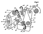
- the transmission rod 64 moves while remaining perpendicular to the oblong holes 52. It drives the axis 46, the stirrup 40 of which it is integral and the movable contact 28 integral with the stirrup until a closed contact position shown in Figure 5, in which the movable contact 28 is in contact with the fixed contact 24 and the contact pressure spring 36 is compressed about halfway.
- the control roller 74 maintains the closing latch 126 against the force of the latch return spring 126.
- the locking spring closure 106 is partially disbanded, due to the mutual closeness of the ankles 72 and 108.
- the opening springs 98 of the side poles remain bandaged, from the makes the ankles 100 immobile with respect to the ankles 102.
- the direction of the result of the forces applied by the closing spring 106 on the parallelogram 56 is defined by the geometric axis of the closing spring 106 which passes through the pin 72 and the pin 108 and is parallel to the plan of Figures 2 to 5, the point of application of the result of the forces applied by the closing spring 106 on the parallelogram 56 is located on the pin 72.
- the upstream static transmission ratio defined by the ratio: ⁇ 0 C 0 / R, where R is the modulus of the result of the forces transmitted by the closing spring 106 in the parallelogram 56 and C 0 is the absolute value of the moment with respect to the geometric axis of the shaft 53 of the result of the forces transmitted by the spring 106 to the parallelogram 56, increases in value r absolute, so that the ratio ⁇ 0 is higher at the end of the closing stroke than at the beginning.
- the direction of the forces transmitted by the transmission rod 64 to the axis 46 integral with the stirrup 40 during closing is essentially perpendicular to the longitudinal axis of the oblong lumen 70 and parallel to the longitudinal axis of the holes. oblong 52.
- the opening of the circuit breaker 10 is initiated by the rotation of the opening latch 116, in response to a manual or automatic trigger order.
- the pivoting of the half-moon 116 releases the multifunction cam 88 from the central pole, and with it the camshaft 80.
- the multifunction cam 88 and the camshaft 80 rotate clockwise.
- the concave surface 90 of the multifunction cam 88 enters in contact with the opening roller 76 and pivots the control lever 60 in the clockwise, causing the parallelogram 56 to fold back.
- the transmission rod 64 drives the axis 46 in translation in the direction of opening.
- the circuit breaker is then returned to the position shown in Figure 2.
- the invention is not limited to the embodiment described above. In particular, it applies as well to a three-phase apparatus as to an apparatus single phase. Various variants are possible.
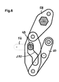
- the figure shows a second embodiment of the invention, which does not differ from the first mode only by the shape of the light 270 of the transmission rod.
- the form selected curve allows to influence the transmission ratio during the closing and opening.
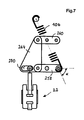
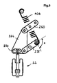
- FIG. 7 and 8 schematically represent a variant according to a third embodiment of the invention, comprising a vacuum interrupter 222 and a parallelogram mechanism comprising a crank lever 258, a control lever 260 and a transmission rod 264 provided of a light 270.
- This variant differs from the first embodiment in that the axis of the connecting rod 264, that is to say the geometric axis perpendicular and intersecting with the two pivot axes of the connecting rod 264, is parallel to the axis of the vacuum interrupter 222.
- the lever arm of the closing spring is relatively small due to its angle of inclination ⁇ relative to the crank lever, while its tension is maximum.
- the angle of inclination ⁇ of the spring relative to the crank lever approaches the right angle so that the transmission ratio ⁇ 1 increases.
- the ratio ⁇ 2 also increases, so that in this embodiment also the overall transmission ratio ⁇ increases.
- FIG. 9 represents a variant according to a fourth embodiment of the invention which makes it possible to control the opening and the closing of a circuit breaker, the movable contact member 328 of which includes contact 328a mounted pivoting with respect to an axis 328b fixed to a support 328c which pivots itself relative to an axis 328d fixed to the chassis of the mechanism.
- a contact spring 336 provides contact pressure in the closed position.
- the drive mechanism, and in particular the parallelogram 356, is similar to that of the first embodiment. The connection between the parallelogram 356 and the contact member 328 is ensured by a link 346.
- control of the mechanism can make calls for a separation between arming and initiating closure. It is enough for this that the closing pin 85 is omitted on the cocking shaft, and that a independent means is used to rotate the closing latch.
- the opening spring (s) can either be placed on the central pole and / or on the side poles. The same applies to the closing spring or springs.
- Ankles 102 and 108 are not necessarily coaxial. Close command is not necessarily duplicated on each of the poles.
- the opening command can be arranged on a side pole. It can also be duplicated on each of the poles.
Abstract
Description
L'invention concerne un mécanisme d'entraínement d'un organe de contact mobile d'un appareillage de coupure.The invention relates to a drive mechanism of a movable contact member of a switchgear.
Elle concerne en particulier, bien que de manière non exclusive, les mécanismes d'entraínement destinés à des appareillages de coupure dont un organe de contact est mobile en translation, tels que les ampoules à vide par exemple. Elle trouve toutefois également une application à des appareillages de coupure dont le contact mobile est mobile en rotation, mais est accouplé à un organe d'entrée lui-même mobile en translation.It concerns in particular, although not exclusively, the mechanisms drives intended for switchgear with a contact member mobile in translation, such as vacuum bulbs for example. However, she finds also an application to switchgear whose mobile contact is mobile in rotation, but is coupled to an input member which is itself mobile in translation.
La demande de brevet FR-A-2 681 723 décrit un mécanisme à deux parallélogrammes permettant la commande d'une ampoule à vide, mû par un ressort. Le mécanisme décrit ne permet que des déplacements angulaires de très faible amplitude des deux parallélogrammes, qui ne se déforment que très légèrement entre la position ouverte et la position fermée du mécanisme. De ce fait, le rapport de transmission d'effort du mécanisme est quasiment constant. En d'autres termes, la force appliquée par le mécanisme à la tige de l'ampoule est dans un rapport quasiment constant avec la force appliquée par le ressort. Comme la force appliquée par le ressort au mécanisme diminue au cours de la détente proportionnellement à l'allongement du ressort, la force appliquée par le mécanisme à la tige de l'ampoule diminue donc elle aussi au cours du mouvement de fermeture. Or les efforts à appliquer à la tige de l'ampoule sont plus important à la fin de la fermeture qu'au début, puisque le mécanisme doit à ce moment assurer une pression de contact suffisante. Cette contrainte impose de surdimensionner le ressort de fermeture. L'énergie de fermeture est alors inutilement élevée, d'où une usure importante des pièces qui conduit à surdimensionner également ces dernières.Patent application FR-A-2 681 723 describes a mechanism with two parallelograms allowing the control of a vacuum bulb, driven by a spring. The mechanism described does not allows only very small angular displacements of the two parallelograms, which only slightly deform between the open position and the closed position of the mechanism. Therefore, the effort transmission ratio of the mechanism is almost constant. In other words, the force applied by the mechanism at the stem of the bulb is in an almost constant relationship with the force applied by the spring. As the force applied by the spring to the mechanism decreases during the expansion in proportion to the elongation of the spring, the force applied by the mechanism at the stem of the bulb therefore also decreases during movement closing. However, the efforts to apply to the bulb stem are greater at the end of the closure than at the beginning, since the mechanism must at this time ensure pressure sufficient contact. This constraint requires oversizing the closing spring. The closing energy is then unnecessarily high, resulting in significant wear of the parts. which also leads to oversize of the latter.
Un objet de la présente invention est de proposer un mécanisme d'entraínement d'un appareillage de coupure tel qu'une ampoule à vide, qui ne présente pas les inconvénients identifiés ci-dessus, et assure notamment un rapport de transmission des efforts important en fin de course de fermeture, de sorte que la force résiduelle du ressort de fermeture partiellement débandé en fin de course de fermeture soit suffisante pour assurer la pression de contact.An object of the present invention is to provide a drive mechanism for a switchgear such as a vacuum interrupter, which does not have the drawbacks identified above, and in particular ensures a significant effort transmission report at the end of the closing stroke, so that the residual force of the closing spring partially unloaded at the end of the closing stroke is sufficient to ensure the contact pressure.
Cet objectif est atteint grâce à un mécanisme d'entraínement d'un organe de contact d'un appareillage de coupure comportant un châssis, l'organe de contact étant lié à un organe d'entraínement et mobile conjointement avec celui-ci par rapport au châssis entre une position de séparation et une position de contact, le mécanisme comportant :
- un parallélogramme articulé, comportant un premier levier pivotant autour d'un premier axe géométrique fixe par rapport au châssis, un deuxième levier pivotant autour d'un deuxième axe géométrique fixe par rapport au châssis, une bielle de transmission pivotant autour d'un troisième axe géométrique fixe par rapport au deuxième levier, et pivotant autour d'un quatrième axe géométrique fixe par rapport au premier levier, les quatre axes géométriques étant parallèles les uns aux autres, la distance séparant le premier et le deuxième axes géométriques étant égale à la distance séparant le troisième et le quatrième axes géométriques, la distance séparant le premier et le quatrième axes géométriques étant égale à la distance séparant le deuxième et le troisième axes géométriques, le parallélogramme étant apte à passer d'une position d'ouverture à une position de fermeture par un pivotement du premier levier autour du premier axe et du deuxième levier autour du deuxième axe,
- un ressort de fermeture apte à appliquer une force motrice au parallélogramme tendant à entraíner celui-ci de sa position d'ouverture à sa position de fermeture,
- des moyens de transmission du mouvement de la bielle de transmission à l'organe d'entraínement, tels que le mouvement de la bielle de transmission engendré par le passage du parallélogramme de sa position d'ouverture à sa position de fermeture entraíne l'organe d'entraínement de la position de séparation à la position de contact,
- le ressort de fermeture et les moyens de transmission sont disposés de telle
manière que le mécanisme produit un rapport de transmission statique global
défini par le rapport
τ = F / R,
où F est le module de la résultante des forces transmises par la bielle de transmission à l'organe d'entraínement lorsque le ressort applique une force de résultante R au parallélogramme en l'absence de mouvement, qui est plus élevé en position de contact qu'en position de séparation.
- an articulated parallelogram, comprising a first lever pivoting around a first geometric axis fixed relative to the frame, a second lever pivoting around a second geometric axis fixed relative to the frame, a transmission rod pivoting around a third axis fixed geometric relative to the second lever, and pivoting around a fourth fixed geometric axis relative to the first lever, the four geometric axes being parallel to each other, the distance separating the first and second geometric axes being equal to the distance separating the third and fourth geometric axes, the distance separating the first and fourth geometric axes being equal to the distance separating the second and third geometric axes, the parallelogram being able to pass from an open position to a position of closing by pivoting the first lever around the first axis and the second e lever around the second axis,
- a closing spring capable of applying a motive force to the parallelogram tending to drive the latter from its open position to its closed position,
- means for transmitting the movement of the transmission rod to the drive member, such as the movement of the transmission rod generated by the passage of the parallelogram from its open position to its closed position causes the member to 'drive from the separation position to the contact position,
- the closing spring and the transmission means are arranged in such a way that the mechanism produces an overall static transmission ratio defined by the ratio
τ = F / R,
where F is the modulus of the result of the forces transmitted by the transmission rod to the drive member when the spring applies a resultant force R to the parallelogram in the absence of movement, which is higher in the contact position than 'in separation position.
Ainsi la diminution de la force appliquée par le ressort et due à la détente partielle de celui-ci lors de la fermeture est-elle au moins partiellement compensée par l'augmentation du rapport de transmission. Préférentiellement, l'augmentation du rapport de transmission est continue entre la position de séparation et la position de contact. Thus the decrease in the force applied by the spring and due to the partial relaxation of at closing, is this at least partially offset by the increase of the transmission report. Preferably, the increase in the transmission ratio is continuous between the separation position and the contact position.
Il est à noter que les rapports de transmission dont il est question dans cet exposé sont des rapports de transmission statiques, tels qu'on peut les mesurer lorsque les pièces en jeu sont immobiles. Plus précisément, les rapports de transmission considérés peuvent être mesurés dans chaque position du mécanisme, en immobilisant l'organe de contact ou l'organe d'entraínement dans la position choisie. C'est ce que traduit l'expression " en l'absence de mouvement " utilisé précédemment.Note that the transmission relationships discussed in this talk are static transmission ratios, such as can be measured when the parts in play are immobile. More specifically, the transmission ratios considered can be measured in each position of the mechanism, immobilizing the contact member or the drive member in the selected position. This is what the expression "in the absence of movement "used previously.
Préférentiellement, les moyens de transmission sont tels que le mécanisme produit un rapport de transmission statique aval défini par le rapport : τ1 = F / C1 où F est le module de la résultante des forces transmises par la bielle de transmission à l'organe d'entraínement lorsqu'un couple dont le moment par rapport à l'axe du premier levier vaut C1 en valeur absolue est appliqué au parallélogramme en l'absence de mouvement, rapport qui est plus élevé en position de contact qu'en position de séparation. Cette augmentation concourt au moins partiellement à l'augmentation du rapport de transmission global τ.Preferably, the transmission means are such that the mechanism produces a downstream static transmission ratio defined by the ratio: τ 1 = F / C 1 where F is the modulus of the result of the forces transmitted by the connecting rod to the member when a torque whose moment relative to the axis of the first lever is equal to C 1 in absolute value is applied to the parallelogram in the absence of movement, a ratio which is higher in the contact position than in the position separation. This increase contributes at least partially to the increase in the overall transmission ratio τ.
Préférentiellement, le ressort de fermeture est agencé de telle manière que le mécanisme produit un rapport de transmission amont défini par le rapport : τ0 = C0 / R où R est le module de la résultante des forces transmises par le ressort de fermeture au parallélogramme et C0 est la valeur absolue du moment par rapport au premier axe géométrique de la résultante des forces transmises par le ressort de fermeture au parallélogramme en l'absence de mouvement, qui est plus élevé en position de contact de l'organe d'entraínement qu'en position de séparation de l'organe d'entraínement. Cette augmentation concourt au moins partiellement à l'augmentation du rapport de transmission global τ.Preferably, the closing spring is arranged in such a way that the mechanism produces an upstream transmission ratio defined by the ratio: τ 0 = C 0 / R where R is the modulus of the result of the forces transmitted by the closing spring to the parallelogram and C 0 is the absolute value of the moment with respect to the first geometric axis of the result of the forces transmitted by the closing spring to the parallelogram in the absence of movement, which is higher in the contact position of the drive member that in the separation position of the drive member. This increase contributes at least partially to the increase in the overall transmission ratio τ.
Selon un mode de réalisation de l'invention, le premier levier comporte un organe de liaison au ressort de fermeture, et le deuxième levier comporte un organe de liaison à un verrou de fermeture apte à interdire le mouvement du parallélogramme de sa position d'ouverture à sa position de fermeture. Cette disposition offre une grande liberté dans le positionnement spatial du point d'application de la force de fermeture.According to one embodiment of the invention, the first lever comprises a member for connection to the closing spring, and the second lever comprises a connecting member to a closing latch capable of preventing movement of the parallelogram from its position opening to its closed position. This arrangement offers great freedom in the spatial positioning of the point of application of the closing force.
Selon un mode de réalisation de l'invention, le premier levier comporte un organe de liaison au ressort de fermeture, et le deuxième levier comporte un organe de liaison à des moyens d'application d'une force motrice d'ouverture. Cette disposition offre une grande liberté dans le positionnement spatial du point d'application de la force de fermeture et du point d'application de la force d'ouverture. According to one embodiment of the invention, the first lever comprises a member for connection to the closing spring, and the second lever comprises a member for connecting to means for applying an opening driving force. This arrangement offers great freedom in the spatial positioning of the point of application of the closing force and the point of application of the opening force.
Selon un mode de réalisation de l'invention, les moyens de transmission comprennent des moyens de guidage de l'organe d'entraínement par rapport au châssis, laissant à l'organe d'entraínement au moins un degré de liberté de translation par rapport au châssis.According to one embodiment of the invention, the transmission means comprise means for guiding the drive member with respect to the chassis, leaving the member drive at least one degree of freedom of translation relative to the chassis.
Selon un mode de réalisation de l'invention, les moyens de transmission comprennent des moyens de guidage de l'organe d'entraínement par rapport à la bielle de transmission laissant à l'organe d'entraínement au moins un degré de liberté de translation par rapport à la bielle.According to one embodiment of the invention, the transmission means comprise means for guiding the drive member with respect to the transmission rod leaving the drive member at least a degree of freedom of translation relative to the connecting rod.
Selon un mode de réalisation de l'invention, l'angle de rotation des premier et deuxième leviers entre la position d'ouverture et la position de fermeture est important. Plus l'angle de rotation est important, plus il est facile de modifier les rapports de transmission, puisque ceux-ci varient avec l'angle de rotation.According to one embodiment of the invention, the angle of rotation of the first and second levers between the open position and the closed position is important. The higher the angle rotation is important, the easier it is to modify the transmission ratios, since these vary with the angle of rotation.
Le mécanisme de l'invention est ainsi compatible avec une commande fermé / ouvert et permet de dimensionner aisément indépendamment l'une de l'autre le ressort de fermeture et le ressort d'ouverture.The mechanism of the invention is thus compatible with a closed / open control and allows to easily dimension the closing spring independently of each other and the opening spring.
D'autres avantages et caractéristiques de l'invention ressortiront de la description qui va suivre de différents modes de réalisation de l'invention, donnés à titre d'exemple non limitatifs et représentés aux dessins annexés dans lesquels:
- la figure 1 représente une vue d'un disjoncteur tripolaire selon un premier mode de réalisation de l'invention ;
- la figure 2 représente le mécanisme du disjoncteur selon le premier mode de réalisation de l'invention, suivant la coupe A-A de la figure 1, en position ouvert désarmé ;
- la figure 3 représente le mécanisme du disjoncteur selon le premier mode de réalisation de l'invention, suivant la coupe A-A de la figure 1, en position ouvert armé ;
- la figure 4 représente le mécanisme du disjoncteur selon le premier mode de réalisation de l'invention, suivant la coupe A-A de la figure 1, en début de fermeture ;
- la figure 5 représente le mécanisme du disjoncteur selon le premier mode de réalisation de l'invention, suivant la coupe A-A de la figure 1, en position fermé prêt à ouvrir ;
- la figure 6 représente un détail d'une bielle selon un deuxième mode de réalisation de l'invention ;
- la figure 7 représente schématiquement un troisième mode de réalisation de l'invention, en position ouverte ;
- la figure 8 représente schématiquement un troisième mode de réalisation de l'invention, en position fermée ;
- la figure 9 représente schématiquement un quatrième mode de réalisation de l'invention, en position ouverte.
- FIG. 1 represents a view of a three-pole circuit breaker according to a first embodiment of the invention;
- FIG. 2 represents the mechanism of the circuit breaker according to the first embodiment of the invention, along the section AA in FIG. 1, in the disarmed open position;
- FIG. 3 represents the mechanism of the circuit breaker according to the first embodiment of the invention, along the section AA in FIG. 1, in the armed open position;
- FIG. 4 represents the mechanism of the circuit breaker according to the first embodiment of the invention, according to section AA of FIG. 1, at the start of closing;
- Figure 5 shows the circuit breaker mechanism according to the first embodiment of the invention, along section AA of Figure 1, in the closed position ready to open;
- FIG. 6 represents a detail of a connecting rod according to a second embodiment of the invention;
- FIG. 7 schematically represents a third embodiment of the invention, in the open position;
- FIG. 8 schematically represents a third embodiment of the invention, in the closed position;
- FIG. 9 schematically represents a fourth embodiment of the invention, in the open position.
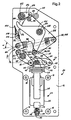
En référence aux figures 1 à 5, un disjoncteur à vide tripolaire 10 comporte un châssis
constitué par des flasques 14 parallèles fixés les uns aux autres et tenus en position par
des entretoises 16, 18. Les flasques 14 séparent trois compartiments polaires 20.Referring to Figures 1 to 5, a three-pole
Chaque compartiment polaire reçoit une ampoule à vide 22 comportant un contact fixe 24
solidaire d'une enveloppe isolante 26, et un contact mobile 28. Un axe matériel de support
30 du contact fixe 24 est monté pivotant par rapport aux deux flasques 14 délimitant le
compartiment. Ce support 30 comporte un alésage 32 de guidage en translation pour une
tige 34 d'extrémité du contact fixe. Un ressort de pression de contact 36 à boudin est
disposé entre le support 30 et le corps de l'enveloppe. Ainsi le contact fixe 24 et
l'enveloppe 26 de l'ampoule à vide 22 sont-ils libres de pivoter avec l'axe 30, et de se
déplacer radialement en translation par rapport à cet axe 30, avec une faible amplitude.Each polar compartment receives a
Le contact mobile 28 comporte une tige dont la tête 40 sort de l'enveloppe et forme un
étrier. Le contact mobile définit un axe géométrique longitudinal qui, lorsque le contact
mobile est centré par rapport à l'enveloppe et situé dans le prolongement du contact fixe,
coïncide avec l'axe géométrique radial de translation de l'enveloppe définie par l'alésage
32. L'étrier 40 comporte deux joues 44 munies chacune d'un alésage. Un axe 46 est
disposé transversalement dans l'étrier et traverse les alésages des joues 44. L'axe 46
supporte un galet central 48 situé entre les joues 44 et deux galets latéraux 50 à ses
extrémités à l'extérieur des joues 44.The
Les deux flasques 14 encadrant chaque pôle comportent deux trous oblongs 52
semblables situés l'un en face de l'autre. Chaque trou oblong 52 définit un axe
longitudinal qui est disposé radialement par rapport à l'axe géométrique de pivotement du
support 30 de l'enveloppe 26. En d'autres termes, l'axe longitudinal de l'oblong 52 coupe
l'axe géométrique de pivotement du support 30 et est perpendiculaire à celui-ci. Les galets
latéraux 50 de l'axe 46 coopèrent chacun avec le trou oblong 52 pratiqué dans le flasque
14 correspondant du châssis 12, de telle sorte que l'étrier 40 est libre de se déplacer en
translation par rapport aux flasques 14 parallèlement aux axes longitudinaux des oblongs,
et de pivoter autour des galets 50.The two
Le mécanisme d'entraínement du contact mobile comporte un étage inférieur, un étage supérieur et un étage de commande. The mechanism for driving the mobile contact comprises a lower stage, a stage upper and a control stage.
L'étage inférieur comporte un barreau de commutation 53 commun aux trois pôles,
constitué par un arbre hexagonal monté dans des paliers supportés par les flasques 14.
Chaque compartiment polaire 20 comporte un parallélogramme articulé 56 constitué d'un
levier de manivelle 58 solidaire du barreau de commutation 53, d'un levier de commande
60 pivotant autour d'un axe 62 supporté par les flasques 14 et d'une bielle de transmission
64. Le levier de manivelle 58 est constitué de deux pièces plates identiques et parallèles
situées de part et d'autre de la bielle de transmission 64 et reliées à celle-ci par
l'intermédiaire d'un axe de pivotement 66, de manière à éviter les porte-à-faux. De même,
le levier de commande 60 est constitué de deux pièces plates identiques et parallèles
situées de part et d'autre de la bielle de transmission 64 et reliées à celle-ci par
l'intermédiaire d'un axe de pivotement 68. La bielle 64 est munie d'une lumière oblongue
70 dont l'axe géométrique longitudinal est perpendiculaire à celui des trous oblongs des
flasques 14 et coupe l'axe géométrique de l'axe 66 et celui de l'axe 68. Les axes 66, 68, 62
et l'arbre 53 sont tous parallèles les uns aux autres et perpendiculaires aux flasques 14. La
bielle 64 est ainsi apte à se déplacer parallèlement à elle-même lorsque le barreau de
commutation 53 pivote. Le galet central 48 de l'axe 46 coopère avec la lumière oblongue
70 de la bielle 64. Ainsi, l'axe 46 coopère à la fois avec la lumière oblongue 70 et avec les
trous oblongs 52, de sorte que sa position est toujours déterminée par la position de
l'intersection entre les trous oblongs 52 et la lumière oblongue 70.The lower stage comprises a switching
Le levier manivelle 58 est muni d'une cheville 72. Le levier de commande 60 est muni
d'un axe 74 sur lequel sont montés deux galets coaxiaux : un galet central 76, dit galet
d'ouverture, situé entre les deux pièces plates du levier de commande, et un galet latéral
77, dit galet de fermeture, situé à l'extérieur de l'une des pièces plates latérales du levier
60.The
L'étage supérieur du mécanisme comporte deux arbres hexagonaux communs aux trois
pôles et montés pivotants par rapport aux flasques, à savoir : un arbre à cames 80 et un
arbre d'armement 82.The upper stage of the mechanism has two hexagonal shafts common to the three
poles and mounted pivoting with respect to the flanges, namely: a
L'arbre d'armement 82 est muni, pour chaque pôle, d'une manivelle d'armement 84
supportant une came d'armement 83 et une cheville de percussion 85. L'arbre d'armement
82 est entraíné en rotation par des moyens d'entraínement non représentés, par exemple un
moteur et/ou par une manette de pompage actionnée à la main. L'accouplement entre
l'arbre d'armement 82 et les moyens d'entraínement comporte une roue libre (non
représentée) qui accouple les moyens d'entraínement à l'arbre lorsque les moyens
d'entraínement transmettent à l'arbre un couple moteur dans le sens horaire, et
désaccouplent les moyens d'entraínement sinon. L'arbre d'armement 82 est en outre
pourvu d'une seconde roue libre (non représentée) par rapport à l'un des flasques 14, qui
interdit la rotation de l'arbre 82 dans le sens inverse des aiguilles d'une montre et autorise
la rotation de l'arbre dans le sens horaire.The cocking
L'arbre à cames 80 est muni de trois cames multifonctions 88 identiques, une par pôle 20.
Chaque came multifonctions 88 comporte une première surface active 90 concave apte à
coopérer avec le galet d'ouverture 76, ainsi qu'une deuxième surface active en escalier
constituée d'une surface en arc de cercle 92 centrée sur l'axe géométrique de l'arbre et
d'une butée de verrouillage 94. Chaque came 88 comporte également un galet 96 destiné
à coopérer avec la came 83 de la manivelle d'armement 84. La came multifonction du pôle
central est rappelée dans le sens horaire sur les figures par un ressort d'ouverture 98 fixé à
une cheville 100 maintenue dans un des flasques latéraux et à une cheville 102 fixée à la
came et excentrée par rapport à son axe de rotation 80. Les cames multifonctions des deux
pôles latéraux sont munies chacune d'un ressort de fermeture 106 dont une extrémité est
accrochée à la came 88 par l'intermédiaire d'une cheville 108 coaxiale avec les chevilles
102 des cames multifonctions latérales, et dont l'autre extrémité est accrochée à la cheville
72 du levier manivelle 58. Sur les figures 3 à 5, on a représenté schématiquement les
ressorts 98 et 106 en traits pleins, bien qu'ils appartiennent à des pôles différents, afin de
mieux visualiser leur action. Les ressorts d'ouverture 98 et de fermeture 106 sont des
ressorts de traction, c'est-à-dire des ressorts dont l'énergie potentielle augmente lorsqu'ils
sont étirés. Le mouvement des cames 88 est limité dans le sens horaire par une butée de
fin de course 110.The
L'étage de commande est localisé entre les flasques du pôle central. Il réunit une commande d'ouverture et une commande de fermeture.The control stage is located between the flanges of the central pole. It brings together a open command and a close command.
La commande d'ouverture comporte, entre les flasques du pôle central, un verrou
d'ouverture 116 en demi-lune façonné sur un axe rotatif 118 supporté par des paliers
montés sur les flasques du pôle central. Ce verrou est destiné à coopérer avec la deuxième
surface active de la came multifonctions 88 du pôle central. Il est rappelé dans le sens
contraire des aiguilles d'une montre sur les figures par un ressort de rappel 120. De
manière connue et non représentée, le verrou 116 est relié à un organe de déclenchement
permettant son déclenchement manuel ou sur défaut électrique.The opening command comprises, between the flanges of the central pole, a
La commande de fermeture comporte, pour chaque pôle 20, la cheville de percussion 85
ainsi qu'un verrou de fermeture 126 constitué par un levier monté fous sur un palier 128
porté par l'arbre hexagonal 80. Le verrou de fermeture 126 est rappelé dans le sens horaire
sur les figures 2 à 5 par un ressort de rappel non représenté. Le verrou 126 comporte un
bras définissant une portée 130 coopérant avec la cheville 85 et un deuxième bras
définissant une surface bombée et une surface de repos, ces deux surfaces étant destinées
à coopérer avec le galet de fermeture 77 du levier de commande 60. Le mouvement du
verrou 126 dans le sens horaire est limité par une butée non représentée. La position de fin
de course dans le sens horaire est une position dite de verrouillage, représentée sur la
figure 2.The closing command comprises, for each
Le fonctionnement du mécanisme sera décrit en référence au pôle central, étant entendu
que les pôles latéraux se déplacent simultanément, l'arbre 53 rendant solidaires les trois
leviers manivelles 58, donc les trois parallélogrammes articulés, alors que le l'arbre 80
rend solidaires les cames multifonctions 88 et que l'arbre 82 rend solidaires les manivelles
d'armement 84.The operation of the mechanism will be described with reference to the central pole, it being understood
that the side poles move simultaneously, the
Le disjoncteur 10 dans son état ouvert désarmé, est représenté sur la figure 2. Dans cette
position, le verrou de fermeture 126 est dans sa position de verrouillage, en butée de fin
de course dans le sens horaire. Le galet de fermeture 77 porte sur la surface bombée du
verrou 126 de telle manière que le moment, par rapport à l'axe de rotation du verrou 126,
de la force appliquée par le galet 77 sur le verrou 126, tende à faire tourner celui-ci dans le
sens horaire. La position du verrou 126 est donc stable. Le verrou 126 empêche la rotation
du levier de commande 60 dans le sens horaire.The
Le ressort d'ouverture 98 et les ressorts de fermeture 106 sont très faiblement bandés et
rappellent les cames multifonctions 88 et avec elles l'arbre à cames 80, dans le sens
horaire, la surface concave 90 étant en contact avec le galet d'ouverture 76. Le ressort de
fermeture 106 tend également à faire tourner le levier manivelle 58 dans le sens horaire,
mais ce mouvement est bloqué du fait de l'interaction entre le levier de commande 60 et
le verrou de fermeture 126. La bielle de transmission 64 se trouve dans une position haute
et maintient l'axe 46, l'étrier 40 et le contact mobile 28 dans une position ouverte de
séparation. Le verrou d'ouverture 116 repose sur l'arc de cercle 92.The
L'armement du mécanisme est produit par la rotation de l'arbre d'armement 82 dans le
sens horaire. La came d'armement 84 entre en contact avec le galet d'armement 96 et
entraíne les cames multifonctions 88 et l'arbre à cames 80 dans le sens contraire des
aiguilles d'une montre. Le verrou de fermeture 126 empêche toute rotation du levier de
commande 60 dans le sens horaire, de sorte que le parallélogramme 56 reste dans sa
position d'ouverture. Le ressort de fermeture 106 et les ressorts d'ouverture 98 se bandent
du fait de la rotation des chevilles 108 et 102 qui s'éloignent des chevilles 72 et 100.
L'arbre à cames 80 atteint une position extrême représentée sur la figure 3, lorsque la
came d'armement 84 et le galet d'armement 96 atteignent une position respective de point
mort. Dans cette position, le verrou d'ouverture 116 a été libéré par la came 92, de sorte
que le verrou 116 a pivoté en position de verrouillage sous l'action de son ressort de
rappel 120.The arming of the mechanism is produced by the rotation of the arming
Dès que la came d'armement 84 dépasse la position de point mort, l'arbre à cames 80
cesse d'être récepteur et devient moteur, sous l'effet des ressorts de fermeture 106 et
d'ouverture 98. La came multifonctions 88 pivote sous la sollicitation des ressorts
d'ouverture 98 et de fermeture 106, jusqu'à rencontrer le verrou d'ouverture 116. Dans
cette phase, le mouvement du galet d'armement 96 est transmis à la came 84 et l'arbre
d'armement 82 pivote dans le sens horaire. La cheville 85 vient alors percuter la portée
130 du verrou de fermeture 126 et entraíne ce dernier dans le sens inverse des aiguilles
d'une montre, comme le montre la figure 4. Le verrou de fermeture 126 libère alors le
galet 77 du levier de commande 60, de sorte que le parallélogramme 56 se déforme par
pivotement du levier de commande 60 et du levier manivelle 58 dans le sens horaire sous
la sollicitation du ressort de fermeture 106, la came multifonctions 88 restant bloquée
dans le sens horaire par le verrou d'ouverture 116. La bielle de transmission 64 se déplace
tout en restant perpendiculaire aux trous oblongs 52. Elle entraíne l'axe 46, l'étrier 40 dont
il est solidaire et le contact mobile 28 solidaire de l'étrier jusqu'à ce que soit atteinte une
position fermée de contact représentée sur la figure 5, dans laquelle le contact mobile 28
est en contact avec le contact fixe 24 et le ressort de pression de contact 36 est comprimé
environ à mi-course. En position de fermeture, le galet de commande 74 maintient le
verrou de fermeture 126 contre la force du ressort de rappel du verrou 126. Le ressort de
fermeture 106 est partiellement débandé, du fait du rapprochement mutuel des chevilles
72 et 108. Les ressorts d'ouverture 98 des pôles latéraux restent quant à eux bandés, du
fait de l'immobilité des chevilles 100 par rapport aux chevilles 102.As soon as the arming
Durant le mouvement de fermeture, la direction de la résultante des forces appliquées par
le ressort de fermeture 106 sur le parallélogramme 56 est définie par l'axe géométrique du
ressort de fermeture 106 qui passe par la cheville 72 et la cheville 108 et est parallèle au
plan des figures 2 à 5, le point d'application de la résultante des forces appliquées par le
ressort de fermeture 106 sur le parallélogramme 56 est situé sur la cheville 72. Durant la
fermeture, du fait de l'ouverture progressive de l'angle α entre l'axe géométrique du
ressort de fermeture 106 et le levier de manivelle 58, le rapport de transmission statique
amont défini par le rapport : τ0 = C0 / R, où R est le module de la résultante des forces
transmises par le ressort de fermeture 106 au parallélogramme 56 et C0 est la valeur
absolue du moment par rapport à l'axe géométrique de l'arbre 53 de la résultante des
forces transmises par le ressort 106 au parallélogramme 56, augmente en valeur absolue,
de sorte que le rapport τ0 est plus élevé à la fin de la course de fermeture qu'au début.During the closing movement, the direction of the result of the forces applied by the
Par ailleurs, la direction des efforts transmis par la bielle de transmission 64 à l'axe 46
solidaire de l'étrier 40 durant la fermeture est essentiellement perpendiculaire à l'axe
longitudinal de la lumière oblongue 70 et parallèle à l'axe longitudinal des trous oblongs
52. Par conséquent, durant la fermeture, du fait de l'ouverture progressive de l'angle β
entre l'axe longitudinal de la lumière oblongue 70 et le levier manivelle 58, le rapport de
transmission statique aval défini par le rapport : τ1 = F / C1, où F est le module de la
résultante des forces transmises par la bielle de transmission 64 à l'axe 46 lorsqu'un
couple dont le moment par rapport à l'axe du premier levier vaut C1 en valeur absolue est
appliqué à l'arbre 53 du parallélogramme 56, augmente, de sorte que le rapport τ1 est plus
élevé à la fin de la course de fermeture qu'au début.Furthermore, the direction of the forces transmitted by the
Globalement, le rapport de transmission statique global τ = F/R augmente durant la fermeture et est plus élevé à la fin de la course de fermeture qu'au début.Overall, the overall static transmission ratio τ = F / R increases during the closing and is higher at the end of the closing stroke than at the beginning.
On peut aisément modifier l'augmentation du rapport de transmission statique, notamment
en modifiant le positionnement de l'axe géométrique du ressort de fermeture. Pour ce
faire, il suffit de modifier l'emplacement respectif des chevilles 72 et 108, par exemple en
déplaçant la cheville 108 sur la came multifonctions.One can easily modify the increase in the static transmission ratio, in particular
by modifying the positioning of the geometric axis of the closing spring. For this
do, just change the respective location of the
L'ouverture du disjoncteur 10 est initiée par la rotation du verrou d'ouverture 116, en
réponse à un ordre de déclenchement manuel ou automatique. Le pivotement de la demi-lune
116 libère la came multifonctions 88 du pôle central, et avec elle l'arbre à cames 80.
Sous la sollicitation du ressort d'ouverture 98, la came multifonctions 88 et l'arbre à came
80 pivotent dans le sens horaire. La surface concave 90 de la came multifonctions 88 entre
en contact avec le galet d'ouverture 76 et fait pivoter le levier de commande 60 dans le
sens horaire, entraínant le repliement du parallélogramme 56. La bielle de transmission 64
entraíne l'axe 46 en translation dans le sens de l'ouverture. Le mouvement d'ouverture
s'achève lorsque la came multifonctions 88 rencontre la butée de fin de course 110. Le
disjoncteur est alors retourné dans la position représentée sur la figure 2.The opening of the
Naturellement, l'invention n'est pas limitée au mode de réalisation décrit ci-dessus. En particulier, elle s'applique aussi bien à un appareillage triphasé qu'à un appareillage monophasé. Diverses variantes sont possibles. Naturally, the invention is not limited to the embodiment described above. In particular, it applies as well to a three-phase apparatus as to an apparatus single phase. Various variants are possible.
La figure représente un deuxième mode de réalisation de l'invention, qui ne diffère du premier mode que par la forme de la lumière 270 de la bielle de transmission. La forme incurvée choisie permet d'influer sur le rapport de transmission durant la course de fermeture et d'ouverture.The figure shows a second embodiment of the invention, which does not differ from the first mode only by the shape of the light 270 of the transmission rod. The form selected curve allows to influence the transmission ratio during the closing and opening.
Les figures 7 et 8 représentent schématiquement une variante selon un troisième mode de
réalisation de l'invention, comportant une ampoule à vide 222 et un mécanisme à
parallélogramme comportant un levier de manivelle 258, un levier de commande 260 et
une bielle de transmission 264 munie d'une lumière 270. Cette variante diffère du premier
mode de réalisation en ce que l'axe de la bielle 264, c'est-à-dire l'axe géométrique
perpendiculaire et sécant avec les deux axes de pivotement de la bielle 264, est parallèle à
l'axe de l'ampoule à vide 222. En position ouverte sur la figure 7, le bras de levier du
ressort de fermeture est relativement faible du fait de son angle d'inclinaison α par rapport
au levier manivelle, alors que sa tension est maximale. Lors de la fermeture, l'angle
d'inclinaison α du ressort par rapport au levier manivelle se rapproche de l'angle droit de
sorte que le rapport de transmission τ1 augmente. Simultanément, le rapport τ2 augmente
également, de sorte que dans ce mode de réalisation également le rapport de transmission
global τ augmente.Figures 7 and 8 schematically represent a variant according to a third embodiment of the invention, comprising a vacuum interrupter 222 and a parallelogram mechanism comprising a
L'invention est applicable non seulement à l'ouverture et la fermeture d'ampoules à vides
de disjoncteurs ou d'interrupteurs, mais également à la fermeture et l'ouverture d'autres
types d'organes de contact dont la position peut être déterminée par un mouvement de
translation de faible amplitude. Ainsi, la figure 9 représente une variante selon un
quatrième mode de réalisation de l'invention qui permet de commander l'ouverture et la
fermeture d'un disjoncteur dont l'organe de contact mobile 328 comporte des doigts de
contact 328a montés pivotant par rapport à un axe 328b fixé à un support 328c qui pivote
lui-même par rapport à un axe 328d fixé au châssis du mécanisme. Un ressort de contact
336 assure la pression de contact en position fermée. Le mécanisme d'entraínement, et
notamment le parallélogramme 356, est semblable à celui du premier mode de réalisation.
La liaison entre le parallélogramme 356 et l'organe de contact 328 est assurée par une
biellette 346.The invention is applicable not only to the opening and closing of empty ampoules
circuit breakers or switches, but also when closing and opening other
types of contact members whose position can be determined by a movement of
low amplitude translation. Thus, FIG. 9 represents a variant according to a
fourth embodiment of the invention which makes it possible to control the opening and the
closing of a circuit breaker, the
D'autres variantes sont possibles. En particulier, la construction faisant appel à des pièces
plates doubles n'est pas obligatoire. Par ailleurs, la commande du mécanisme peut faire
appelle à une séparation entre l'armement et le déclenchement de la fermeture. Il suffit
pour cela que soit omise la cheville de fermeture 85 sur l'arbre d'armement, et qu'un
moyen indépendant soit utilisé pour faire pivoter le verrou de fermeture. Other variations are possible. In particular, construction using parts
double plates is not compulsory. In addition, the control of the mechanism can make
calls for a separation between arming and initiating closure. It is enough
for this that the
Suivant l'énergie nécessaire, le nombre de ressort d'ouverture et de fermeture peut varier.
Le ou les ressorts d'ouverture peuvent être indifféremment placés sur le pôle central et/ou
sur les pôles latéraux. Il en va de même du ou des ressorts de fermeture. Les chevilles 102
et 108 ne sont pas nécessairement coaxiales. La commande de fermeture n'est pas
nécessairement dupliquée sur chacun des pôles. La commande d'ouverture peut être
disposée sur un pôle latéral. Elle peut également être dupliquée sur chacun des pôles.Depending on the energy required, the number of opening and closing springs may vary.
The opening spring (s) can either be placed on the central pole and / or
on the side poles. The same applies to the closing spring or springs.
Claims (8)
τ = F / R,
où F est le module de la résultante des forces transmises par la bielle de transmission à l'organe d'entraínement lorsque le ressort applique une force de résultante R au parallélogramme en l'absence de mouvement, qui est plus élevé en position de contact qu'en position de séparation.
τ = F / R,
where F is the modulus of the result of the forces transmitted by the transmission rod to the drive member when the spring applies a resultant force R to the parallelogram in the absence of movement, which is higher in the contact position than 'in separation position.
Applications Claiming Priority (2)
| Application Number | Priority Date | Filing Date | Title |
|---|---|---|---|
| FR0000229 | 2000-01-10 | ||
| FR0000229A FR2803685B1 (en) | 2000-01-10 | 2000-01-10 | ARTICULATED PARALLELOGRAM MECHANISM FOR DRIVING A CONTACT MEMBER OF AN ELECTRICAL SWITCHING APPARATUS |
Publications (2)
| Publication Number | Publication Date |
|---|---|
| EP1117111A1 true EP1117111A1 (en) | 2001-07-18 |
| EP1117111B1 EP1117111B1 (en) | 2006-07-26 |
Family
ID=8845735
Family Applications (1)
| Application Number | Title | Priority Date | Filing Date |
|---|---|---|---|
| EP20000410150 Expired - Lifetime EP1117111B1 (en) | 2000-01-10 | 2000-12-07 | Actuating mechanism of a contact element of an electrical switch with an articulated parallelogram |
Country Status (4)
| Country | Link |
|---|---|
| EP (1) | EP1117111B1 (en) |
| DE (1) | DE60029555T2 (en) |
| ES (1) | ES2265900T3 (en) |
| FR (1) | FR2803685B1 (en) |
Cited By (2)
| Publication number | Priority date | Publication date | Assignee | Title |
|---|---|---|---|---|
| CN102184799A (en) * | 2011-01-07 | 2011-09-14 | 无锡市锡山湖光电器有限公司 | A manual break-brake automatic reset device of a vacuum feeder switch |
| CN105742087A (en) * | 2016-04-26 | 2016-07-06 | 亚洲电力设备(深圳)股份有限公司 | High-current isolation switch |
Families Citing this family (1)
| Publication number | Priority date | Publication date | Assignee | Title |
|---|---|---|---|---|
| DE102020203288A1 (en) | 2020-03-13 | 2021-09-16 | Siemens Aktiengesellschaft | Circuit breaker device with multiple switching units |
Citations (2)
| Publication number | Priority date | Publication date | Assignee | Title |
|---|---|---|---|---|
| FR1303015A (en) * | 1961-07-10 | 1962-09-07 | Comp Generale Electricite | Switch of the compensated type in which the electrodynamic loop forces are used to oppose repulsion at the contact points |
| EP0593371A1 (en) * | 1992-10-13 | 1994-04-20 | Schneider Electric Sa | Operating mechanism for a switch with three positions |
-
2000
- 2000-01-10 FR FR0000229A patent/FR2803685B1/en not_active Expired - Fee Related
- 2000-12-07 EP EP20000410150 patent/EP1117111B1/en not_active Expired - Lifetime
- 2000-12-07 ES ES00410150T patent/ES2265900T3/en not_active Expired - Lifetime
- 2000-12-07 DE DE2000629555 patent/DE60029555T2/en not_active Expired - Fee Related
Patent Citations (2)
| Publication number | Priority date | Publication date | Assignee | Title |
|---|---|---|---|---|
| FR1303015A (en) * | 1961-07-10 | 1962-09-07 | Comp Generale Electricite | Switch of the compensated type in which the electrodynamic loop forces are used to oppose repulsion at the contact points |
| EP0593371A1 (en) * | 1992-10-13 | 1994-04-20 | Schneider Electric Sa | Operating mechanism for a switch with three positions |
Cited By (2)
| Publication number | Priority date | Publication date | Assignee | Title |
|---|---|---|---|---|
| CN102184799A (en) * | 2011-01-07 | 2011-09-14 | 无锡市锡山湖光电器有限公司 | A manual break-brake automatic reset device of a vacuum feeder switch |
| CN105742087A (en) * | 2016-04-26 | 2016-07-06 | 亚洲电力设备(深圳)股份有限公司 | High-current isolation switch |
Also Published As
| Publication number | Publication date |
|---|---|
| EP1117111B1 (en) | 2006-07-26 |
| FR2803685A1 (en) | 2001-07-13 |
| FR2803685B1 (en) | 2002-03-01 |
| DE60029555T2 (en) | 2007-08-09 |
| DE60029555D1 (en) | 2006-09-07 |
| ES2265900T3 (en) | 2007-03-01 |
Similar Documents
| Publication | Publication Date | Title |
|---|---|---|
| EP0593371B1 (en) | Operating mechanism for a switch with three positions | |
| WO2011144629A2 (en) | Device for unlocking a landing gear in a deployed position and a landing gear comprising one such device | |
| FR2818796A1 (en) | CLOSING ASSISTANCE MECHANISM FOR ELECTRICAL SWITCHING APPARATUS AND DRIVE MECHANISM OF ELECTRICAL APPARATUS PROVIDED WITH SUCH AN ASSISTANCE MECHANISM | |
| EP1170769A1 (en) | Snap closing mechanism for modular circuit breaker | |
| EP2040276B1 (en) | Device for controlling the opening and/or closing of the electrical contacts in an electrical apparatus and electrical apparatus containing such a device | |
| FR2640424A1 (en) | CIRCUIT BREAKER CONTROL | |
| EP1237169B1 (en) | High voltage circuir breaker with spring actuator with an additional energy recuperating spring | |
| FR2775717A1 (en) | Mechanism for opening and closing an opening such as door on vehicle, using cable operation to simplify mechanism and reduce cost | |
| WO2020020866A1 (en) | Emergency opening device for an aircraft door, comprising a retaining member with a hook | |
| EP1117111A1 (en) | Actuating mechanism of a contact element of an electrical switch with an articulated parallelogram | |
| FR2921198A1 (en) | ACTUATION BY A MAIN SHAFT ASSEMBLY AND SECONDARY TREES OF A BREAKER BREAKER ALTERNATOR DISCONNECT | |
| EP2717284B1 (en) | Operating device of an electric protection apparatus and electric protection apparatus comprising same | |
| FR2606450A1 (en) | ELECTRICALLY ACTUATED LOCK FOR MOUNTING ON MOTOR VEHICLES | |
| FR2583570A1 (en) | MOLDED CASE CIRCUIT BREAKER. | |
| EP0895260B1 (en) | Fast control device for a high tension switching device, particularly an earthing switch | |
| EP1178505B1 (en) | Actuating mechanism with tow chain for electrical high voltage switches | |
| FR2546476A1 (en) | LANDING DEVICE FOR AIRCRAFT STRUCTURE | |
| EP3657522B1 (en) | Mechanism for controlling the opening and closing of a current interruption device for an electrical switch | |
| FR2610760A1 (en) | MANUALLY CONTROLLED LOW-VOLTAGE MULTIPOLAR AUTOMATIC SWITCH | |
| EP1178506A1 (en) | Operating mechanism with chain and starting device for electrical high voltage switches | |
| EP3762955B1 (en) | Synchronised movement of a bistable device, from a multitude of monostable levers | |
| EP1670009B1 (en) | Operation mechanism for a multipole switch | |
| EP3232459B1 (en) | Electric line protection apparatus | |
| FR2812762A1 (en) | High voltage circuit breaker handle movement mechanism having chassis mounted transmission shaft handle driven driving transmission shaft from neutral position and engaging command lock. | |
| FR3116503A1 (en) | Railway detector with mechanical timer |
Legal Events
| Date | Code | Title | Description |
|---|---|---|---|
| PUAI | Public reference made under article 153(3) epc to a published international application that has entered the european phase |
Free format text: ORIGINAL CODE: 0009012 |
|
| AK | Designated contracting states |
Kind code of ref document: A1 Designated state(s): DE ES GB IT SE |
|
| AX | Request for extension of the european patent |
Free format text: AL;LT;LV;MK;RO;SI |
|
| 17P | Request for examination filed |
Effective date: 20011018 |
|
| AKX | Designation fees paid |
Free format text: DE ES GB IT SE |
|
| RAP1 | Party data changed (applicant data changed or rights of an application transferred) |
Owner name: SCHNEIDER ELECTRIC INDUSTRIES SAS |
|
| GRAP | Despatch of communication of intention to grant a patent |
Free format text: ORIGINAL CODE: EPIDOSNIGR1 |
|
| GRAS | Grant fee paid |
Free format text: ORIGINAL CODE: EPIDOSNIGR3 |
|
| GRAA | (expected) grant |
Free format text: ORIGINAL CODE: 0009210 |
|
| AK | Designated contracting states |
Kind code of ref document: B1 Designated state(s): DE ES GB IT SE |
|
| REG | Reference to a national code |
Ref country code: GB Ref legal event code: FG4D Free format text: NOT ENGLISH |
|
| REF | Corresponds to: |
Ref document number: 60029555 Country of ref document: DE Date of ref document: 20060907 Kind code of ref document: P |
|
| REG | Reference to a national code |
Ref country code: SE Ref legal event code: TRGR |
|
| GBT | Gb: translation of ep patent filed (gb section 77(6)(a)/1977) |
Effective date: 20061116 |
|
| REG | Reference to a national code |
Ref country code: ES Ref legal event code: FG2A Ref document number: 2265900 Country of ref document: ES Kind code of ref document: T3 |
|
| PLBE | No opposition filed within time limit |
Free format text: ORIGINAL CODE: 0009261 |
|
| STAA | Information on the status of an ep patent application or granted ep patent |
Free format text: STATUS: NO OPPOSITION FILED WITHIN TIME LIMIT |
|
| 26N | No opposition filed |
Effective date: 20070427 |
|
| PGFP | Annual fee paid to national office [announced via postgrant information from national office to epo] |
Ref country code: IT Payment date: 20081224 Year of fee payment: 9 Ref country code: SE Payment date: 20081205 Year of fee payment: 9 |
|
| PGFP | Annual fee paid to national office [announced via postgrant information from national office to epo] |
Ref country code: ES Payment date: 20090120 Year of fee payment: 9 |
|
| PGFP | Annual fee paid to national office [announced via postgrant information from national office to epo] |
Ref country code: DE Payment date: 20081205 Year of fee payment: 9 |
|
| PGFP | Annual fee paid to national office [announced via postgrant information from national office to epo] |
Ref country code: GB Payment date: 20081203 Year of fee payment: 9 |
|
| EUG | Se: european patent has lapsed | ||
| GBPC | Gb: european patent ceased through non-payment of renewal fee |
Effective date: 20091207 |
|
| PG25 | Lapsed in a contracting state [announced via postgrant information from national office to epo] |
Ref country code: DE Free format text: LAPSE BECAUSE OF NON-PAYMENT OF DUE FEES Effective date: 20100701 |
|
| PG25 | Lapsed in a contracting state [announced via postgrant information from national office to epo] |
Ref country code: GB Free format text: LAPSE BECAUSE OF NON-PAYMENT OF DUE FEES Effective date: 20091207 |
|
| REG | Reference to a national code |
Ref country code: ES Ref legal event code: FD2A Effective date: 20110304 |
|
| PG25 | Lapsed in a contracting state [announced via postgrant information from national office to epo] |
Ref country code: IT Free format text: LAPSE BECAUSE OF NON-PAYMENT OF DUE FEES Effective date: 20091207 |
|
| PG25 | Lapsed in a contracting state [announced via postgrant information from national office to epo] |
Ref country code: SE Free format text: LAPSE BECAUSE OF NON-PAYMENT OF DUE FEES Effective date: 20091208 |
|
| PG25 | Lapsed in a contracting state [announced via postgrant information from national office to epo] |
Ref country code: ES Free format text: LAPSE BECAUSE OF NON-PAYMENT OF DUE FEES Effective date: 20110303 |
|
| PG25 | Lapsed in a contracting state [announced via postgrant information from national office to epo] |
Ref country code: ES Free format text: LAPSE BECAUSE OF NON-PAYMENT OF DUE FEES Effective date: 20091208 |