EP1115083A2 - Chipkarten-Leseanordnung - Google Patents
Chipkarten-Leseanordnung Download PDFInfo
- Publication number
- EP1115083A2 EP1115083A2 EP00127716A EP00127716A EP1115083A2 EP 1115083 A2 EP1115083 A2 EP 1115083A2 EP 00127716 A EP00127716 A EP 00127716A EP 00127716 A EP00127716 A EP 00127716A EP 1115083 A2 EP1115083 A2 EP 1115083A2
- Authority
- EP
- European Patent Office
- Prior art keywords
- card
- shaft
- arrangement
- slot
- flap
- Prior art date
- Legal status (The legal status is an assumption and is not a legal conclusion. Google has not performed a legal analysis and makes no representation as to the accuracy of the status listed.)
- Withdrawn
Links
Images




Classifications
-
- G—PHYSICS
- G06—COMPUTING OR CALCULATING; COUNTING
- G06K—GRAPHICAL DATA READING; PRESENTATION OF DATA; RECORD CARRIERS; HANDLING RECORD CARRIERS
- G06K7/00—Methods or arrangements for sensing record carriers, e.g. for reading patterns
- G06K7/0013—Methods or arrangements for sensing record carriers, e.g. for reading patterns by galvanic contacts, e.g. card connectors for ISO-7816 compliant smart cards or memory cards, e.g. SD card readers
- G06K7/0034—Methods or arrangements for sensing record carriers, e.g. for reading patterns by galvanic contacts, e.g. card connectors for ISO-7816 compliant smart cards or memory cards, e.g. SD card readers the connector being capable of simultaneously receiving a plurality of cards in the same insertion slot
-
- G—PHYSICS
- G06—COMPUTING OR CALCULATING; COUNTING
- G06K—GRAPHICAL DATA READING; PRESENTATION OF DATA; RECORD CARRIERS; HANDLING RECORD CARRIERS
- G06K13/00—Conveying record carriers from one station to another, e.g. from stack to punching mechanism
- G06K13/02—Conveying record carriers from one station to another, e.g. from stack to punching mechanism the record carrier having longitudinal dimension comparable with transverse dimension, e.g. punched card
- G06K13/08—Feeding or discharging cards
-
- G—PHYSICS
- G06—COMPUTING OR CALCULATING; COUNTING
- G06K—GRAPHICAL DATA READING; PRESENTATION OF DATA; RECORD CARRIERS; HANDLING RECORD CARRIERS
- G06K7/00—Methods or arrangements for sensing record carriers, e.g. for reading patterns
- G06K7/0013—Methods or arrangements for sensing record carriers, e.g. for reading patterns by galvanic contacts, e.g. card connectors for ISO-7816 compliant smart cards or memory cards, e.g. SD card readers
-
- G—PHYSICS
- G06—COMPUTING OR CALCULATING; COUNTING
- G06K—GRAPHICAL DATA READING; PRESENTATION OF DATA; RECORD CARRIERS; HANDLING RECORD CARRIERS
- G06K7/00—Methods or arrangements for sensing record carriers, e.g. for reading patterns
- G06K7/0013—Methods or arrangements for sensing record carriers, e.g. for reading patterns by galvanic contacts, e.g. card connectors for ISO-7816 compliant smart cards or memory cards, e.g. SD card readers
- G06K7/0056—Methods or arrangements for sensing record carriers, e.g. for reading patterns by galvanic contacts, e.g. card connectors for ISO-7816 compliant smart cards or memory cards, e.g. SD card readers housing of the card connector
- G06K7/0073—Methods or arrangements for sensing record carriers, e.g. for reading patterns by galvanic contacts, e.g. card connectors for ISO-7816 compliant smart cards or memory cards, e.g. SD card readers housing of the card connector having multiple insertion slots, the respective slots suited for the same or different card form factors
Definitions
- the invention is concerned with the formation of card reading arrangements for Save provided cards.
- card reading arrangements are for with memories provided cards well known, so that no further details on this needs to be received.
- all known card reading arrangements have one have a loading opening provided in which the with a Memory card is inserted. Because such cards to manufacture and / or maintenance of use conditions of electrical devices are used, contacts are formed within the shaft, which, if the Card is inserted into the slot, contacts attached to the card contact and thus the memory of the card with a read and / or Connect writing arrangement. This ensures that only when present of the information stored in the card's memory is used by the respective device can be.
- Such cards provided with memories can, for example, consist of Mobile communication known SIM cards, without which no booking can be run on the net.
- those with memories are provided Cards also designed so that not only in the memory locations of the memory Data for the production and / or maintenance of use conditions are stored, but there are also storage areas in which the user can write data itself.
- SIM cards pointed out that not only the Maintaining the state of use of data used by mobile phones included, but also, for example, phone numbers entered by the user be able to record. This is particularly convenient since the user when he is one another mobile phone is used, with the insertion of "his" SIM card at the same time his phone book stored in the SIM card memory is available.
- the standardization of the memory available in the cards is that for the free one Use of storage space made available by a user is very limited.
- a second also has a loading opening for receiving one with a Memory provided additional card and is on the Assembly arrangement of the second shaft provided a closure arrangement is that the insertion and the at a first slot equipped with a card Removing the additional card in or out of the second slot, Malfunctions are excluded that occur when the the first card booked by the subsequent insertion or booking or due to the early withdrawal or withdrawal of the second card can.
- a Monitoring arrangement is present, which is not an insertion, but it is excludes the booking of a card inserted into the second slot, if the first slot is already equipped with a card, and the one in the second slot inserted card monitors their position in the second slot and when the position changes, the map in the first slot booked out.
- the loading of the shafts is particularly simple if the two shafts are arranged one above the other and the assembly openings of the two shafts point in the same direction.
- the closure arrangement is provided with a locking foot movable flap, which in a first position, the assembly opening of the second Releases the shaft and closes the assembly opening in its second position, the blocking foot for a card inserted in the first slot
- a locking foot movable flap which in a first position, the assembly opening of the second Releases the shaft and closes the assembly opening in its second position, the blocking foot for a card inserted in the first slot
- the card reading arrangement is particularly user-friendly when in accordance with Claim 5 an ejector arrangement is provided on the second shaft, the one card inserted into the second slot from the assembly opening pushes out when the closure arrangement the accessibility of the Assembly arrangement on the second slot releases.
- the effort for the ejector arrangement is very low if according to Claim 6 the ejector arrangement essentially formed by a mechanism that is only by closing and / or opening the closure assembly 24th the mechanical energy for ejecting the one in the second shaft inserted card delivers.
- a second energy accumulator with the closure arrangement connected, and is the card reading arrangement i.ü. as stated in claim 9 trained, it is ensured that the shooting movement of the breech assembly by supporting the energy stored in the second energy store.
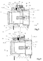
- FIG. 1 shows a housing part 10 which has two assembly openings 11.1 and 11.2. Includes each of the two assembly openings 11.1, 11.2 Shaft 12.1. And 12.2.
- a card 13.1 is inserted into the first slot 12.1, which card with a Memory 14.1 is equipped. There are also spring contacts 15.1 in the shaft 12.1 provided, which with a card inserted into the slot 12.1 13.1 contact surfaces 16.1 connected to memory 14.1.
- a card 13.2 is also inserted into the second slot 12.2. Since it is this card 13.2 by one to manufacture and maintain one Necessary SIM card, this card is also with 13.2 provided a memory 14.2. There are also spring contacts 15.2 in the shaft 12.2 attached, with a card inserted into this slot 12.2 13.2 to the this memory 14.2 connected contact surfaces 16.2 in physical contact stand.
- Each of the contact springs 15 arranged in a shaft 12.1, 12.2 is provided with a Reading and / or writing arrangement 17 connected, with the help of which in the Stores 14.1.
- And 14.2 contain information read out and / or can be registered.
- each shaft 12.1, 12.2 19.1, 19.2, 20.1, 20.2 designed to accommodate a Monitoring arrangement serve.
- this is realized in such a way that a light source 21 in each pocket 19 and a light-sensitive one in each pocket 20 Sensor 22 is arranged, each of the sensors 22 with the reading and / or Writing arrangement 17 is connected.
- This monitoring arrangement has the task of occupying the shafts 12 Cards 13 to monitor or the booking or deregistration process of cards 13 to Taxes.
- a posting process is understood to mean one at which the memory 14 of a card 13 through the contact of the contact springs 15 with the Contact areas with the reading and / or writing arrangement 17 enters into data exchange, while the previously existing data exchange during a deregistration process terminated between a memory 14 and the reading and / or writing arrangement 17 by disconnecting the existing connection .
- the two shafts 12 are equipped with cards 13 as shown in FIG. 1, the at the shaft 12.1 existing and by the inserted card 13.1 interrupted light path the task, the location or the presence of the card 13.1. to control constantly. If the card 13.1 from the slot 12.1 suddenly pulled out in the direction of the arrow P3, this is detected by the one in the pocket 20.1 arranged sensor 22 and reports this to the read and write arrangement 17, whereupon the card 13.2 in slot 12.2 is immediately booked out.
- the contact surfaces 16.1 should be formed so large that the physical contact with the contact springs 16.1 is only released when the The light path at shaft 12.1 is already closed and card 13.2 is fully booked.
- the Monitoring arrangement not shown in connection with FIG. 1 Training is limited, provided that the sensor or sensors used ensure that with a card 13.2 already booked in slot 12.2, no card 13.1 anymore can be booked in slot 12.1 or that with two booked cards 13.1, 13.2 the card 13.2 is always fully booked before the card in the slot 12.1 card 13.1 is booked out.
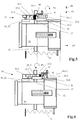
- FIG. 2 shows a mechanical implementation that prevents a Card 13.2 already in slot 12.2 by inserting a card 13.1 in the slot 12.1 the inserted card 13.1 is still booked or one in the Slot 12.1 arranged and booked card 13.1 by pulling it out of the Bay 12.1 is booked out before and in the bay 12.2 booked card 13.2 has been booked out.
- a housing wall 10.1, 10.2 is shown, which is provided with an opening 23. Behind the opening 23 (inside the Housing), the two shafts 12.1 and 12.2 are arranged one above the other, whereby the shaft 12.1 with the card 13.1 and the shaft 12.2 with the card 13.2 is equipped. For reasons of clarity, the illustration of FIG No memory in the cards, the contact surfaces and the spring contacts been.
- FIG. 2 This closure arrangement is essentially formed by a flap 24, the side parts 24 'on a Shaft 25 are rotatably mounted in the direction of arrow P4, P4 '(for storage see also Fig. 3). Furthermore, the flap 24 with an opening 26, a handle 27 and one Locking foot 28 provided. As shown in FIG. 2, the card 13.2 is in the slot 12.2 inserted and the grip strip 27 lies against the housing wall 10.1, close the flap 24 and the card 13.2, the opening 23 2 is clearly shown - the blocking foot 28 of the flap 24 on the Card 13.2 is present, the blocking foot 28 and the handle 27 each Movement of the flap 24 in the direction of arrow P4, P4 'excluded.
- the shaft 12.1 is used for this purpose by one stationary pad 29 and a carriage 30 formed.
- the carriage 30 is in The insertion and ejection direction (P2, P3) of the card 13.1 can be moved with the fixed edition 29 connected.
- gear 34 which is arranged on the shaft 25, which together with the shaft 25 is only a counterclockwise rotation P5 can perform.
- teeth 35 of the gear 34 which have an even number (35.2, 35.4, 35.6, 7) compared to teeth 35, which have an odd number (35.1, 35.3, 35.5, 7), have a greater width in the direction of the shaft axis and that each between two teeth 35 with an even number (35.2, 35.4, 36.6, ...) Tooth 35 is placed with an odd number (35.1, 35.3, 35.5, ).
- Fig. 3 shows a state in which the flap 24 - as shown in Fig. 2 - closed and the slot 12.1 is not yet equipped with a card 13.1.
- the assembly opening 11.1 is in the position 1, which is not only in Fig. 3, but also in Figs. 2 and 6 as a dash-dotted line is marked.
- the flap 24 has a tongue 39, at the free end of which a cam 40 is formed in the distance between two teeth 35 (35.5, 35.6) of Gear 34 engages.
- FIG. 7a relates to a situation which is also shown in FIG. 3 is.
- the illustration according to FIG. 7 a clearly shows that two, in the direction of rotation P5 of the shaft 25 there are ramps 41, 42 arranged one behind the other the steep falling edge 43.1 of the ramp 41 and the base point F2 of the slope 44.2 Ramp 42 are separated by an intermediate area 45. 7a to c can be seen that the ramp 42 is provided with a flattening 46 which in runs essentially parallel to the intermediate region 45.
- the shaft 25 and the gear 34 in the direction (P6, P6 ') of the Shaft axis slidably arranged.
- This mobility of the gear 34 and the shaft 25 ensures that the rotation P5 of the ramps 41, 42 Gear 34 is not hindered, but based on the position shown in FIG. 7a with simultaneous displacement of the gear 34 and the shaft 25 in the direction P6 the even-numbered tooth 35.10 of the gear 34 on the slope 44.1 of the ramp 41 can slide along.
- the tongue 39 can perform a movement in the direction P6 and the rest of the cam 40 on its side facing away from the direction of rotation P5 of the gear wheel 34 with a chamfer 47 is provided, the chamfer 47 comes with a during the closing movement odd tooth 35.5 (Fig.4) of gear 34 in physical contact, whereby the tongue 39 - due to the beginning sliding of the chamfer 47 - in Is bent towards P6. Simultaneously with the completion of the closing movement then snaps cam 40 a distance between an even number and an odd tooth 35.4 and 35.5 of the gear 34, the side of the cam 40 on which the chamfer 47 is formed in the direction of the tooth 35 even numbered ordinal 35.4 points. These relationships are closer in Fig. 5 shown.
- the slide 30 is with a Sliding tongue 48 provided, for better clarity in the representations 3 to 6 is only shown in FIG. 3.
- This sliding tongue 48 points at her free end 49 a hook 50 and a pocket 51 (Fig. 8a to 8e).
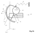
- FIGS. 8a to 8e the flap 24 and Side parts 24 'removable.
- the carriage 30 is in the position pos. 1, which is also shown in Fig. 3. Furthermore, the flap 24 is moved by a movement P1, P4 been opened. The latter is indicated by the fact that the opening 26 of the Flap 24 is in front of the carriage 30 and thus the assembly opening 11.1 is accessible. In addition, the opening movement P1, P4 was associated with the Flap 24 connected spring 52, which forms a second energy accumulator, tensioned.
- FIGS. 8a to 8e a pin is on the side part 24 'of the flap 24 53 is provided, which in the position shown in FIG. 8 a easily into the pocket 51 protrudes. Since the representations of FIGS. 8a to 8e clearly show that the width of the Pocket 51 is larger than the width of the pin 53, when no more force in Direction P1, P4 acts, the rotary movement P4 'caused by the spring 52 does not hindered by the hook 50 when the carriage 30 in the position Pos.1 located.
- the flap 24 can be in again Direction P4 'are closed, with which the processes taking place at the same time have already been explained in connection with FIG. 5. Since one according to Fig. 8c executed closing movement P4 'with no change in position of the slide 30 is connected, the hook gives way under the action of the force acting in the direction P4 ' 50 the pin 53 in the direction of P8, so that when the pin 53 the resistance the hook 51 was overcome, the spring 52 the closing movement in the direction P4 'ended. The flap 24 then reaches a position which is shown in Fig. 8d.
- the flap 24 now starts again from the position shown in FIG. 8d opened by moving the flap in the direction of P1, P4, as in 6 - the carriage 30 from position 2 again in position 1 and the card 13.1 from the insertion opening 11.1 pushed out.
- the free space required to slide card 13.1 out Movement of the carriage 30 is not by the pin 53 and the hook 50 impaired, since the arrangement is so synchronized that the driver 36 (Fig. 3rd to 6) only then no longer of a tooth 35 with an even number Ordinal number 35.4 is hindered (see explanations for Fig. 6) when the pin 53 already during the rotation in the direction of P5 the resistance of the hook 50 has overcome. If the opening movement in the direction of arrow P5 is completed, relationships arise, which are shown in FIG. 8e.
Landscapes
- Engineering & Computer Science (AREA)
- Physics & Mathematics (AREA)
- General Physics & Mathematics (AREA)
- Theoretical Computer Science (AREA)
- Artificial Intelligence (AREA)
- Computer Vision & Pattern Recognition (AREA)
- Conveying Record Carriers (AREA)
- Coupling Device And Connection With Printed Circuit (AREA)
- Management, Administration, Business Operations System, And Electronic Commerce (AREA)
- Control Of Vending Devices And Auxiliary Devices For Vending Devices (AREA)
Abstract
Description
- Fig.1
- eine Karten-Leseanordnung im Seitenschnitt;
- Fig.2
- eine weitere Karten-Leseanordnung im Seitenschnitt;
- Fig.3
- eine Druntersicht auf einen Schieber;
- Fig.4
- eine weitere Darstellung gemäß Fig.3;
- Fig.5
- eine weitere Darstellung gemäß Fig.3;
- Fig.6
- eine weitere Darstellung gemäß Fig. 3;
- Fig.7a-c
- drei Darstellungen von zwei ortfesten Rampen und
- Fig.8a-e
- fünf schematische Darstellungen eines Schiebers mit Klappe.
Claims (9)
- Karten-Leseanordnung
mit einem ersten, eine Bestückungsöffnung 11.1 habenden Schacht 12.2 zur Aufnahme einer mit einem Speicher 14.2 versehenen Karte 13.2
dadurch gekennzeichnet,daß ein zweiter, ebenfalls eine Bestückungsöffnung 11.1 habender Schacht 12.1 zur Aufnahme einer mit einem Speicher 14.1 versehenen weiteren Karte 13.1 vorgesehen ist unddaß an der Bestückungsanordnung 11.1 des zweiten Schachts eine Verschlußanordnung 24 vorgesehen ist, die bei einem mit einer Karte 13.2 bestückten ersten Schacht 12.2 das Einführen und das Entnehmen der weiteren Karte 13.1 in bzw. aus dem zweiten Schacht 12.2 ausschließt. - Karten-Leseanordnung
mit einem ersten, eine Bestückungsöffnung 11.2 habenden Schacht 12.2 zur Aufnahme einer mit einem Speicher 14.2 versehenen Karte 13.2
dadurch gekennzeichnet,daß ein zweiter, ebenfalls eine Bestückungsöffnung 11.1 habender Schacht 12.1 zur Aufnahme einer mit einem Speicher 14.1 versehenen weiteren Karte 13.1 vorgesehen ist unddaß eine Überwachungsanordnung 21,22 vorhanden ist, die ein Einbuchen einer in den zweiten Schacht 12.1 eingeschobenen Karte 13.1 ausschließt, wenn bereits der erste Schacht 12.2 mit einer Karte 13.2 bestückt ist, und die bei einer in der zweiten Schacht 12.1 eingeschobenen Karte 13.1 deren Lage im zweiten Schacht 12.1 überwacht und bei eintretenden Lageänderungen die im ersten Schacht 12.2 befindliche Karte 13.2 ausbucht. - Karten-Leseanordnung nach Anspruch 1 oder Anspruch 2
dadurch gekennzeichnet,
daß die beiden Schächte 12.1, 12.2 übereinander angeordnet sind, wobei die Bestückungsöffnungen 11.1, 11.2 der beiden Schächte 12.1, 12.2 in die gleiche Richtung weisen. - Karten-Leseanordnung nach einem der Ansprüche 1 oder 3
dadurch gekennzeichnet,
daß die Verschlußanordnung eine mit einem Sperrfuß 28 versehene bewegliche Klappe 24 ist, die in einer ersten Stellung die Bestückungsöffnung 11.1 des zweiten Schachts 12.1 freigibt und in ihrer zweiten Stellung die Bestückungsöffnung 11.1 verschließt, wobei der Sperrfuß 28 bei einer in den ersten Schacht 12.2 eingesetzten Karte 12.2 zum Ausschluß der Beweglichkeit der Klappe 24 an der in den ersten Schacht 12.2 befindlichen Karte 13.2 anliegt. - Karten-Leseanordnung nach Anspruch 1, 3 oder 4
dadurch kennzeichnet,
daß eine Auswerferanordnung am zweiten Schacht 12.1 vorgesehen ist, die eine in den zweiten Schacht 12.1 eingeschobene Karte 13.1 aus der Bestückungsöffnung 11.1 herausdrückt, wenn die Verschlußanordnung 24 die Zugänglichkeit der Bestückungsanordnung 11.1 am zweiten Schacht 12.1 freigibt. - Karten-Leseanordnung nach Anspruch 5
dadurch gekennzeichnet,
daß die Auswerferanordnung im wesentlichen von einer Mechanik gebildet ist, die erst durch das Schließen und/oder das Öffnen der Verschlußanordnung 24 die mechanische Energie für das Auswerfen der im zweiten Schacht 12.1 eingeschobenen Karte 13.1 liefert. - Karten-Leseanordnung nach Anspruch 6
dadurch gekennzeichnet,daß die Auswerferanordnung einen in Einschub- und Auswerfrichtung P2, P3 der in der in den zweiten Schacht 12.1 einschiebbaren Karte 13.1 beweglichen Schlitten 30,ein auf einer drehbaren Welle 25 angeordnetes und in Richtung der Wellenachse verschiebbares Zahnrad 34 , dessen Zähne 35 mit geradzahliger Ordnungsziffer (35.2, 35.4, 35.6,...) im Vergleich zu den Zähnen 35 mit ungeradzahliger Ordnungsziffer (35.1, 35.3, 35.5,...) in Richtung der Wellenachse eine größere Breite haben,einen mit dem Schlitten 30 verbundenen Mitnehmer 36, dessen eine vordere Kante 37 zum körperlichen Kontakt mit den Zähnen 35 mit geradzahliger Ordnungsziffer (35.2, 35.4, 35.6,...) bestimmt ist und dessen Längskante 38 einen geringen Abstand zu den Zähnen 35 mit ungeradzahliger Ordnungsziffer (35.1, 35.3, 35.5,...) einhält,eine mit der Verschlußanordnung 24 verbundene Zunge 39, die nicht nur in Richtung der Wellenachse, sondern auch in Drehrichtung der Welle 25 beweglich ist und die an ihrem freien Ende einen zum Eingriff in den Abstand zwischen einem gerad- und einem ungeradzahligen Zahn 35 (35.1, 35.2; 35.2, 35.3) des Zahnrades 34 bestimmten Nocken 40 hat,zwei ortsfeste, in Drehrichtung der Welle 25 hintereinander angeordnete Rampen 41,42, die zeitweise mit den Stirnflächen der Zähne 35 mit geradzahliger Ordnungsziffer (35.2, 35.4, 35.6,...) in körperlichem Kontakt stehen, und einen ersten Kraftspeicher 33 aufweist, der mit dem Schlitten 30 verbunden ist. - Karten-Leseanordnung nach Anspruch 7
dadurch gekennzeichnet,
daß ein zweiter Kraftspeicher 52 vorhanden ist, der mit der Verschlußanordnung 52 verbunden ist und der, wenn die Verschlußanordnung 24 geöffnet ist, Energie gespeichert hat. - Karten-Leseanordnung nach Anspruch 8
dadurch gekennzeichnet,daß mit dem Schlitten 30 eine Gleitzunge 48 verbunden ist, die den Bewegungen des Schlittens 30 folgt und deren freies Ende als beweglicher Haken 50 ausgebildet ist, unddaß an der Verschlußanordnung 24 ein Zapfen 53 vorgesehen ist, der, wenn die Verschlußanordnung 24 zum Einschieben einer Karte 13.1 in den Schacht 12.1, vom beweglichen Haken 50 zur Verhinderung der Entladung der im zweiten Kraftspeicher 52 gespeicherten Energie arretiert wird.
Applications Claiming Priority (2)
| Application Number | Priority Date | Filing Date | Title |
|---|---|---|---|
| DE19963403 | 1999-12-28 | ||
| DE19963403A DE19963403A1 (de) | 1999-12-28 | 1999-12-28 | Karten-Leseanordnung |
Publications (2)
| Publication Number | Publication Date |
|---|---|
| EP1115083A2 true EP1115083A2 (de) | 2001-07-11 |
| EP1115083A3 EP1115083A3 (de) | 2002-04-03 |
Family
ID=7934770
Family Applications (1)
| Application Number | Title | Priority Date | Filing Date |
|---|---|---|---|
| EP00127716A Withdrawn EP1115083A3 (de) | 1999-12-28 | 2000-12-18 | Chipkarten-Leseanordnung |
Country Status (3)
| Country | Link |
|---|---|
| US (2) | US6959864B2 (de) |
| EP (1) | EP1115083A3 (de) |
| DE (1) | DE19963403A1 (de) |
Families Citing this family (11)
| Publication number | Priority date | Publication date | Assignee | Title |
|---|---|---|---|---|
| US7295443B2 (en) | 2000-07-06 | 2007-11-13 | Onspec Electronic, Inc. | Smartconnect universal flash media card adapters |
| US6438638B1 (en) | 2000-07-06 | 2002-08-20 | Onspec Electronic, Inc. | Flashtoaster for reading several types of flash-memory cards with or without a PC |
| DE10143309A1 (de) * | 2001-09-04 | 2002-05-16 | Grundig Ag | Lesegerät für unterschiedliche Kartentypen |
| US6976623B1 (en) * | 2002-11-18 | 2005-12-20 | Onspec Electronic, Inc. | Flash juke box |
| EP1688003A1 (de) * | 2003-11-28 | 2006-08-09 | Nokia Corporation | Mobiltelefon und verfahren zum betrieb des mobiltelefons |
| CN103311715B (zh) * | 2012-03-08 | 2015-08-12 | 深圳富泰宏精密工业有限公司 | 保护盖组件、应用保护盖组件的电子装置及使用保护盖组件拆装功能卡的方法 |
| CN103428313B (zh) * | 2012-05-21 | 2016-02-10 | 中兴通讯股份有限公司 | 一种客户识别模块卡兼容装置及终端设备 |
| JP5648024B2 (ja) * | 2012-07-10 | 2015-01-07 | 日本電産サンキョー株式会社 | カードリーダ |
| EP3229179A1 (de) * | 2012-09-28 | 2017-10-11 | Nidec Sankyo Corporation | Kartenleser |
| JP6893445B2 (ja) * | 2017-06-28 | 2021-06-23 | 日本電産サンキョー株式会社 | カードリーダ |
| CN108898036B (zh) * | 2018-06-20 | 2021-06-29 | 南京沁恒微电子股份有限公司 | 一种数据读写控制方法 |
Family Cites Families (18)
| Publication number | Priority date | Publication date | Assignee | Title |
|---|---|---|---|---|
| JPS61278989A (ja) * | 1985-06-04 | 1986-12-09 | Toppan Moore Co Ltd | Icカ−ドのリ−ダ・ライタ |
| EP0236846B1 (de) * | 1986-02-28 | 1991-01-02 | Siemens Aktiengesellschaft | Ver- und Entriegelungseinrichtung für einen Kartenleser |
| DE3736258A1 (de) * | 1987-10-27 | 1989-05-11 | Mannesmann Kienzle Gmbh | Datenkartenanordnung |
| ATE182999T1 (de) * | 1988-10-14 | 1999-08-15 | Omron Tateisi Electronics Co | Kartenlesegerät mit verriegelung |
| IL111151A (en) * | 1994-10-03 | 1998-09-24 | News Datacom Ltd | Secure access systems |
| US5979773A (en) * | 1994-12-02 | 1999-11-09 | American Card Technology, Inc. | Dual smart card access control electronic data storage and retrieval system and methods |
| EP0826288B1 (de) * | 1996-03-18 | 2000-09-13 | News Datacom Ltd. | Chipkartenkopplung für pay-tv-systeme |
| DE19624079C1 (de) * | 1996-06-17 | 1998-01-29 | Bosch Gmbh Robert | Kartenleser für Chipkarten |
| US5763862A (en) * | 1996-06-24 | 1998-06-09 | Motorola, Inc. | Dual card smart card reader |
| US5894597A (en) * | 1996-09-24 | 1999-04-13 | Motorola, Inc. | Communication device for different sized cards |
| JPH10302030A (ja) * | 1997-02-28 | 1998-11-13 | Toshiba Corp | 接続装置、および情報処理装置 |
| DE29723669U1 (de) * | 1997-05-06 | 1998-12-10 | DDM Hopt + Schuler GmbH & Co KG, 78628 Rottweil | Kartenleser |
| DE19719275C2 (de) * | 1997-05-07 | 2000-05-04 | Juergen Dethloff | System mit einem tragbaren Terminal und damit verbindbaren Datenträgern |
| GB9722551D0 (en) * | 1997-10-25 | 1997-12-24 | Ncr Int Inc | Card reader |
| US5933328A (en) * | 1998-07-28 | 1999-08-03 | Sandisk Corporation | Compact mechanism for removable insertion of multiple integrated circuit cards into portable and other electronic devices |
| US6824045B2 (en) * | 2000-04-20 | 2004-11-30 | Canon Kabushiki Kaisha | Method and system for using multiple smartcards in a reader |
| US6601329B2 (en) * | 2001-03-13 | 2003-08-05 | Vaudreuil Rene | Card holder |
| US6578302B1 (en) | 2001-06-21 | 2003-06-17 | Idl Incorporated | Sign assembly |
-
1999
- 1999-12-28 DE DE19963403A patent/DE19963403A1/de not_active Withdrawn
-
2000
- 2000-12-18 EP EP00127716A patent/EP1115083A3/de not_active Withdrawn
- 2000-12-21 US US09/746,132 patent/US6959864B2/en not_active Ceased
-
2007
- 2007-11-01 US US11/933,674 patent/USRE41825E1/en not_active Expired - Lifetime
Also Published As
| Publication number | Publication date |
|---|---|
| US6959864B2 (en) | 2005-11-01 |
| EP1115083A3 (de) | 2002-04-03 |
| USRE41825E1 (en) | 2010-10-19 |
| US20010019077A1 (en) | 2001-09-06 |
| DE19963403A1 (de) | 2001-07-12 |
Similar Documents
| Publication | Publication Date | Title |
|---|---|---|
| DE69213555T2 (de) | Kontaktgeber für Karten mit Schaltkreis | |
| DE60303699T2 (de) | Kartenverbinder mit Kartenverriegelungsmechanismus | |
| DE69835629T2 (de) | Verbinder für eine Chipkarte | |
| DE60212483T2 (de) | Kartenverbinder mit erster und zweiter Aufnahmeposition | |
| EP1205875B1 (de) | Aufnahmevorrichtung für Datenkarten | |
| DE19963403A1 (de) | Karten-Leseanordnung | |
| EP2002379B1 (de) | Kartenleser nach dem push-push-system | |
| WO2004053783A1 (de) | Chipkartenaufnahme mit einem auswerfer und mindestens einem mit diesem gekoppelten verriegelungsarm | |
| EP1623362B1 (de) | Kartenaufnahmevorrichtung | |
| EP0236846A1 (de) | Ver- und Entriegelungseinrichtung für einen Kartenleser | |
| DE19640457A1 (de) | Positionierungsmechanismus für einen beweglichen Steckverbinder | |
| DE69830889T2 (de) | Kontaktgerät für eine Smart-Karte | |
| DE69202259T2 (de) | Gerät zur Zusammenarbeit mit einer Kassette. | |
| DE2707363A1 (de) | Vorrichtung zum erfassen und verschieben einer kassette in einem bandgeraet | |
| EP0686294A1 (de) | Münzpfandschloss | |
| DE2411182A1 (de) | Kartenkassette | |
| DE69110718T2 (de) | Informationswiedergabegerät. | |
| DE3145705C2 (de) | Vorrichtung zum Auslesen und/oder Einspeichern einer Information aus beziehungsweise in eine einen Speicher für die Information aufweisende, während des Informationsaustausches feststehende Karte | |
| DE10332583A1 (de) | Kartenverbinderanordnung | |
| DE10047954C2 (de) | Rahmenstruktur zum Einbauen von Einschubplatten | |
| DE3346209A1 (de) | Kassettenfuehrungsmechanismus fuer ein tonbandgeraet | |
| DE10113336A1 (de) | Münzpfandschloß | |
| DE1950820B2 (de) | Kartenregister | |
| DE1966088C3 (de) | Kassetten-Magnetbandgerät. Ausscheidung aus: 1911224 | |
| DE2139480A1 (de) |
Legal Events
| Date | Code | Title | Description |
|---|---|---|---|
| PUAI | Public reference made under article 153(3) epc to a published international application that has entered the european phase |
Free format text: ORIGINAL CODE: 0009012 |
|
| AK | Designated contracting states |
Kind code of ref document: A2 Designated state(s): AT BE CH CY DE DK ES FI FR GB GR IE IT LI LU MC NL PT SE TR |
|
| AX | Request for extension of the european patent |
Free format text: AL;LT;LV;MK;RO;SI |
|
| PUAL | Search report despatched |
Free format text: ORIGINAL CODE: 0009013 |
|
| RAP1 | Party data changed (applicant data changed or rights of an application transferred) |
Owner name: NOKIA CORPORATION |
|
| AK | Designated contracting states |
Kind code of ref document: A3 Designated state(s): AT BE CH CY DE DK ES FI FR GB GR IE IT LI LU MC NL PT SE TR |
|
| AX | Request for extension of the european patent |
Free format text: AL;LT;LV;MK;RO;SI |
|
| AKX | Designation fees paid | ||
| REG | Reference to a national code |
Ref country code: DE Ref legal event code: 8566 |
|
| STAA | Information on the status of an ep patent application or granted ep patent |
Free format text: STATUS: THE APPLICATION IS DEEMED TO BE WITHDRAWN |
|
| 18D | Application deemed to be withdrawn |
Effective date: 20021004 |