EP1114914A1 - End cap for roller shutter box - Google Patents
End cap for roller shutter box Download PDFInfo
- Publication number
- EP1114914A1 EP1114914A1 EP00460075A EP00460075A EP1114914A1 EP 1114914 A1 EP1114914 A1 EP 1114914A1 EP 00460075 A EP00460075 A EP 00460075A EP 00460075 A EP00460075 A EP 00460075A EP 1114914 A1 EP1114914 A1 EP 1114914A1
- Authority
- EP
- European Patent Office
- Prior art keywords
- heel
- cheek
- tunnel
- shutter device
- clip
- Prior art date
- Legal status (The legal status is an assumption and is not a legal conclusion. Google has not performed a legal analysis and makes no representation as to the accuracy of the status listed.)
- Granted
Links
- 239000011324 bead Substances 0.000 claims description 19
- 238000005096 rolling process Methods 0.000 claims description 7
- 238000007789 sealing Methods 0.000 claims 4
- 238000006073 displacement reaction Methods 0.000 abstract description 2
- 239000000428 dust Substances 0.000 abstract 2
- 238000007599 discharging Methods 0.000 abstract 1
- 238000010276 construction Methods 0.000 description 4
- 229910052782 aluminium Inorganic materials 0.000 description 2
- XAGFODPZIPBFFR-UHFFFAOYSA-N aluminium Chemical compound [Al] XAGFODPZIPBFFR-UHFFFAOYSA-N 0.000 description 2
- 239000004793 Polystyrene Substances 0.000 description 1
- 230000006978 adaptation Effects 0.000 description 1
- 230000004888 barrier function Effects 0.000 description 1
- 238000000605 extraction Methods 0.000 description 1
- 238000009413 insulation Methods 0.000 description 1
- 238000004519 manufacturing process Methods 0.000 description 1
- 229910052751 metal Inorganic materials 0.000 description 1
- 239000002184 metal Substances 0.000 description 1
- 239000004033 plastic Substances 0.000 description 1
- 229920002223 polystyrene Polymers 0.000 description 1
- 230000002787 reinforcement Effects 0.000 description 1
- 230000003014 reinforcing effect Effects 0.000 description 1
- 230000000284 resting effect Effects 0.000 description 1
Images


Classifications
-
- E—FIXED CONSTRUCTIONS
- E06—DOORS, WINDOWS, SHUTTERS, OR ROLLER BLINDS IN GENERAL; LADDERS
- E06B—FIXED OR MOVABLE CLOSURES FOR OPENINGS IN BUILDINGS, VEHICLES, FENCES OR LIKE ENCLOSURES IN GENERAL, e.g. DOORS, WINDOWS, BLINDS, GATES
- E06B9/00—Screening or protective devices for wall or similar openings, with or without operating or securing mechanisms; Closures of similar construction
- E06B9/02—Shutters, movable grilles, or other safety closing devices, e.g. against burglary
- E06B9/08—Roll-type closures
- E06B9/11—Roller shutters
- E06B9/17—Parts or details of roller shutters, e.g. suspension devices, shutter boxes, wicket doors, ventilation openings
- E06B9/174—Bearings specially adapted therefor
-
- E—FIXED CONSTRUCTIONS
- E06—DOORS, WINDOWS, SHUTTERS, OR ROLLER BLINDS IN GENERAL; LADDERS
- E06B—FIXED OR MOVABLE CLOSURES FOR OPENINGS IN BUILDINGS, VEHICLES, FENCES OR LIKE ENCLOSURES IN GENERAL, e.g. DOORS, WINDOWS, BLINDS, GATES
- E06B9/00—Screening or protective devices for wall or similar openings, with or without operating or securing mechanisms; Closures of similar construction
- E06B9/02—Shutters, movable grilles, or other safety closing devices, e.g. against burglary
- E06B9/08—Roll-type closures
- E06B9/11—Roller shutters
- E06B9/17—Parts or details of roller shutters, e.g. suspension devices, shutter boxes, wicket doors, ventilation openings
- E06B9/17007—Shutter boxes; Details or component parts thereof
- E06B9/1703—Fixing of the box; External plastering of the box
Definitions
- the present invention relates to a shutter device made of preferably made of plastic, and intended to close each of the lateral ends of a rolling shutter tunnel.
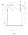
- tunnel boxes are designed to be integrated during the elevation to the masonry of a building above window openings or door, as shown in Fig. 1.
- the lateral ends of the tunnel safe are in particular embedded in the masonry.
- Each tunnel box generally consists of a molded shell having a tunnel-shaped recess with the lower part open to accommodate a roller shutter.
- the arch of the recess can be in a semicircle or with cut sides.
- the vault is extended by jambs which delimit the external faces of the recess and the width of the opening.
- the legs of the tunnel can be the same thickness. In that case, the tunnel safe is said to be symmetrical.
- the legs of the tunnel box can be of different thicknesses.
- the tunnel safe is said to be asymmetrical.
- Each leg is provided at its end with a metal reinforcing profile generally aluminum, one of its peculiarities is to include a U-shaped groove. This groove is oriented towards the inside of the boot, so that these grooves face each other.
- the width of the profile which covers the end of each leg is identical. It is defined by the thickness of said end of the thinnest leg.
- the profile is always positioned in relation to the outside face said leg.
- the profile of the the thickest leg is set back from the internal face of said leg, from the difference in thickness between the two legs.
- each tunnel safe After having been cut to the necessary size to adapt it to the length of the opening that will receive it, each tunnel safe receives each of its lateral ends a shutter device.
- a shutter device for a tunnel safe consists mainly of a cheek and a heel perpendicular to it.
- the length of the tunnel tunnel portion that will be integrated into the masonry corresponds to the length of the heel.
- the heel When installing a shutter device on a lateral end of the tunnel safe, the heel is inserted into the U-shaped grooves of the profiles for slide there until the shutter device is in place.
- the shutter device can be in one piece, that is to say that the heel is integral with the cheek as a result of the method of manufacturing the shutter device.
- the heel is offset laterally with respect to the cheek, depending on whether the shutter device is mounted at a end or the other. Therefore, the use of a one-piece shutter device will require two types of shutter, one left or one right, which can to be fitted respectively in one and the other of the lateral ends.
- the cheek and the heel are put in place one after the other during the mounting of the shutter device in a lateral end of the tunnel safe.
- the assembly time of the shutter device is increased.
- the object of the invention is therefore to propose a shutter device for rolling shutter tunnel that can be mounted in either the other of the lateral ends of a symmetrical or asymmetrical tunnel box, without require adaptation of the heel to the cheek during assembly of the obturator device.
- the shutter device of a roller shutter tunnel tunnel comprising in particular a cheek intended to close a lateral end of said tunnel box and a heel, intended to partially close an internal recess opening into the lower part of said tunnel safe, the shutter device is remarkable in that it comprises means provided to allow the assembly of the heel to the cheek, allowing lateral travel of the heel relative to the cheek.
- the shutter device can be assembled, before being mounted indifferently in one or other of the lateral ends of a tunnel safe.
- three sets of means developed below allow everyone to obtain an assembled shutter device before being mounted in either side end of a tunnel safe and allowing a lateral displacement of the heel relative to the cheek.
- the first set of means consists of at least one flexible connecting leg extending one end of the heel and terminated by a clip, each assembly tab being provided for pass through an opening made through the cheek, said clip being provided for grip on the outside of the cheek opposite the heel to staple the heel in the cheek when the heel abuts against the cheek.
- the width of each opening is greater than the width of each assembly tab.
- the openings and / or the tabs are arranged in staggered rows, the clips being arranged so alternated on their assembly legs to distribute over two parallel generators the forces transmitted by the clips between the heel and the cheek.
- the second set of means to allow the assembly of the cheek to the heel, allowing a clearance lateral of one with respect to the other consists of at least one portion which is separated partially and laterally of the cheek by forming a retractable clip located in a end edge of the cheek intended to fit into a transverse groove formed in the heel, said retractable clip being intended to be received in a cutout made in one face of said transverse groove of the heel.
- the width of each cut is more important than the width of each retractable clip.
- the third set of means for assembling the cheek to the heel by allowing movement lateral of one with respect to the other consists of at least two beads located in the extension of the cheek and whose outer lateral ends are terminated respectively by chamfers, said beads being provided to be slide into a housing made in a transverse groove formed in the heel, said housing comprising a portion which is detached partially and laterally from the transverse groove in the central part of the heel to serve as a clip, said portion being provided, on the one hand, for opening during passage of a chamfer of a bead and, on the other hand, to close between the two beads.
- the length of the portion is less than the distance between the two beads.
- the heel consists of a heel short assembled to the cheek and a raised heel to the short heel by at least one tongue that can be removed in a groove formed in the heel.
- the tunnel safe 400 shown in FIG. 1 is intended to be integrated into the masonry M above the doorway of a window or door of a building. he is in particular embedded in the masonry M by its two end sides side 402 and 404.
- the shutter device D shown in FIG. 2 is globally constituted a cheek 100 and a heel 300.
- the shutter device D is intended to be mounted laterally in each lateral ends 402 or 404 of an internally hollowed-out tunnel tunnel 400, so as to close airtight said lateral end of the tunnel safe 400.
- the tunnel safe 400 is represented by honeycomb cells with Figs. 2, 3, 5, 8 and 10.
- the tunnel safe 400 consists of a shell based on polystyrene delimited in length by two lateral ends 402 and 404 of which only the lateral end 402 is visible in this FIG.
- the internal recess of the tunnel safe 400 has the form of a tunnel, the arch of which V is connected on both sides to two legs J1 and J2, whose thicknesses can be different.
- the J2 thicker jamb is placed towards the interior part of the building to form thermal and sound insulation.
- Two aluminum reinforcement profiles 406a and 406b overlap respectively the ends of the legs J1 and J2.
- Each profile 406a or 406b has a U-shaped groove.
- the U-shaped openings of the profiles 406a and 406b are positioned opposite one another.
- the cheek 100 of the shutter device D comprises a support edge 110 of constant thickness consisting of an arch 112 extended by two straight segments 114a and 114b.
- the support edge 110 is designed to closely fit the walls internal of the vault V and the J1 and J2 legs so as to ensure the precise positioning of the cheek 100 relative to a lateral end 402 or 404 of tunnel safe 400.
- the support edge 110 is connected perpendicularly to a plate 120 whose internal face is visible in this FIG.
- the plate 120 has housings 122 provided to accommodate the accessories of a roller shutter axis of a suitable model and its mechanism maneuver.
- the plate 120 is extended at its periphery in the same plane by a flange 126 perpendicular to the support edge 110.
- the flange 126 is intended to come into contact with a lateral end 402 or 404 of a tunnel safe 400 to serve as an axial stop for the shutter device D during assembly and form a tight barrier to the passage of air between the internal recess of the tunnel-safe 400 and the interior insulating lining of the building.
- the heel 300 is stapled through the plate 120 of a cheek 100 in its lower part opposite the arch 112 and perpendicular to said cheek 100.
- the heel 300 makes it possible to seat the tunnel-trunk by resting on the element masonry M on which it rests and support the mass of the shutter attached to the plate 120 of the cheek 100.
- the heel 300 is formed in FIG. 3 of an extended main plate 310 by a fixing lug 320 allowing the fixing of a sub-face 410 represented in fine lines.
- This underside 410 is a plate designed to close the recess internal part of the lower part of the tunnel safe 400, leaving a passage for the unfolding of the roller shutter deck.
- the main plate 310 laterally has edges 312a and 312b which are intended to be housed in the U-shaped openings of the profiles 406a and 406b, as shown in FIG. 2.
- this heel 300 is at least equal to the dimension taken at the bottom of the U-shaped openings of sections 406a and 406 b.
- the length 1 of the main plate 310 is at least equal to the length L for fitting a lateral end 402 or 404 of a tunnel safe 400 in masonry M. Only the lateral end 402 is visible in this FIG.
- the fixing lug 320 formed at one end of the heel 300 is of a width lower than that of the heel 300, as shown in FIG. 2.
- the first set of means for assembling the heel to the cheek allowing lateral movement of one relative to the other is visible to Figs. 3 and 4.
- the end of the main plate 310 opposite the tab of fixing 320 has flexible assembly legs 330 each terminated by a staple 332.
- Rectangular openings 150 also visible in FIG. 4 are performed through the plate 120 in the lower part of the cheek 100.
- the openings 150 are arranged so as to allow the respective passage assembly tabs 330 of the heel 300 therethrough.
- the staples 332 can take hold on the outer face of the cheek 100 to staple the heel 300 in said cheek 100, as shown in FIG. 4.
- the openings 150 are staggered through the plate 120.
- staples 332 they are arranged alternately on their legs assembly 330.
- This particular arrangement of the openings 150 and the clips 332 makes it possible to distribute the forces transmitted by staples 332 between two parallel generators cheek 100 and heel 300.
- the stiffness of connection between the cheek 100 and the heel 300 is increased by compared to conventional stapling.
- the width of the openings 150 is larger than the width of the assembly tabs 330.
- This construction allows lateral deflection of the heel 300 relative to the cheek 100 when the heel 300 is assembled in the cheek 100.
- a type of cheek 100 and heel 300 to achieve a shutter device D can be assembled either on one side or the other of the tunnel safe 400, when the latter is asymmetrical, as is shown in Fig. 2.
- the shutter device D Due to its one-piece construction, the shutter device D can be easily installed in the tunnel safe.
- This shutter device D automatically adapts to tunnel boxes asymmetrical when they have J1, J2 legs of different thicknesses.
- It can be mounted on either side or on the other side of the tunnel safe 400.
- the second set of means for assembling the cheek to the heel allowing lateral movement of one relative to the other is visible to Figs. 5, 6, and 7.
- a cheek 100a is assembled perpendicularly in a heel 300a.
- the plate 120 of the cheek 100a present in an end edge 302a opposite the arch 112, clip-shaped portions 332a, separated partially and laterally of the plate 120.
- the end edge 302a of the plate 120 with its retractable clips 332a is intended to fit into a transverse groove 334a, produced in one face of the heel 300a.
- the width of the cutouts 336a is greater than the width of the clips 332a of a value at least equal to the difference in thickness between the two legs of the tunnel safe.
- This construction allows lateral deflection of the heel 300a relative to the cheek 100a when said cheek 100a is assembled in a heel 300a.
- a type of cheek 100a and heel 300a can be assembled either on one side or the other side of the tunnel safe 400, when the latter is asymmetrical, as is shown in Fig. 2.
- the shutter device thus produced can be easily placed in the lateral ends of a tunnel safe.
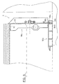
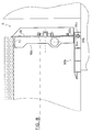
- the third set of means allowing the lateral assembly of the cheek in the heel allowing lateral movement of one relative to the other is visible to Figs. 8, 9 and 9a.
- a cheek 100b is assembled laterally in a heel 300b.
- an end edge 302b of the plate 120, arranged opposite to the arch 112 is terminated by beads 330b and 331b, of which only the bead 330b is visible in this FIG.
- the beads 330b and 331b can be mounted to slide in a cylindrical housing 333b provided in a transverse groove 334b produced in one face of the heel 300b and close to one of its ends.
- the transverse groove 334b crosses right through the width of the heel 300b.
- the housing 333b has a portion 335b which is separated partially and laterally of the transverse groove 334b in the central part of said transverse groove 334b to obtain an elasticity of its walls which go function as a clip.
- the length of the portion 335b is less than the distance separating the bead 330b from the bead 331b, which then allows a lateral travel of the heel 300b relative to the cheek 100b when the heel 300b is assembled in the cheek 100b.
- a type of cheek 100b and heel 300b can be assembled either on one side or the other side of the tunnel safe 400, when the latter is asymmetrical, as is shown in Fig. 2.
- the heels 300, 300a, 300b, of the three shutter devices presented can be in one piece as shown in Figs. 3, 5 and 8, or in two elements as shown in FIG. 10 or on the detail in Fig. 6.
- a heel 300c consists, on the one hand, of a short heel 304c directly assembled to a cheek 100c and, on the other hand, a heel piece 302c.
- Heel piece 302c is intended to be inserted into profiles 406a and 406b of a tunnel safe 400 before mounting the shutter device D in a lateral end 402 of said tunnel safe 400 to be finally brought into contact and emberée à le talle 304c.
- this Fig. Only the section 406a is shown.
- the short heel 304c has in its upper part at at least one groove 306c which makes it possible to receive respectively at least one tongue 308c or, and which extends the upper face of the heel piece 302c.
- the heel piece 302c is removed from the short heel 304c to partially close the internal recess opening into the lower part of said tunnel safe 400, as also appears in Figs. 6 and 10.
Landscapes
- Structural Engineering (AREA)
- Engineering & Computer Science (AREA)
- Architecture (AREA)
- Civil Engineering (AREA)
- Operating, Guiding And Securing Of Roll- Type Closing Members (AREA)
- Spinning Or Twisting Of Yarns (AREA)
- Package Closures (AREA)
- Processing Of Meat And Fish (AREA)
- Preliminary Treatment Of Fibers (AREA)
- Cleaning In General (AREA)
- Road Paving Machines (AREA)
- Slide Fasteners (AREA)
- Specific Sealing Or Ventilating Devices For Doors And Windows (AREA)
- Extrusion Moulding Of Plastics Or The Like (AREA)
Abstract
Description
La présente invention concerne un dispositif obturateur fabriqué de préférence en matière plastique, et destiné à fermer chacune des extrémités latérales d'un coffre-tunnel pour volet roulant.The present invention relates to a shutter device made of preferably made of plastic, and intended to close each of the lateral ends of a rolling shutter tunnel.
Habituellement, les coffres-tunnels sont prévus pour être intégrés en cours de l'élévation à la maçonnerie d'un bâtiment au-dessus des embrasures de fenêtre ou de porte, comme cela est montré à la Fig. 1.Usually, tunnel boxes are designed to be integrated during the elevation to the masonry of a building above window openings or door, as shown in Fig. 1.
Les extrémités latérales du coffre-tunnel sont en particulier encastrées dans la maçonnerie.The lateral ends of the tunnel safe are in particular embedded in the masonry.
Chaque coffre-tunnel est généralement constitué d'une coque moulée comportant un évidement en forme de tunnel dont la partie inférieure est ouverte pour permettre d'y loger un volet roulant.Each tunnel box generally consists of a molded shell having a tunnel-shaped recess with the lower part open to accommodate a roller shutter.
La voûte de l'évidement peut être en demi-cercle ou à pans coupés. La voûte se prolonge par des jambages qui délimitent les faces externes de l'évidement et la largeur de l'ouverture.The arch of the recess can be in a semicircle or with cut sides. The vault is extended by jambs which delimit the external faces of the recess and the width of the opening.
Les jambages du coffre-tunnel peuvent être de même épaisseur. Dans ce cas, le coffre-tunnel est dit symétrique.The legs of the tunnel can be the same thickness. In that case, the tunnel safe is said to be symmetrical.
Les jambages du coffre-tunnel peuvent être d'épaisseurs différentes. Dans ce cas, le coffre-tunnel est dit asymétrique. The legs of the tunnel box can be of different thicknesses. In this In this case, the tunnel safe is said to be asymmetrical.
Chaque jambage est pourvu à son extrémité d'un profilé métallique de renfort généralement en aluminium, dont une de ses particularités est de comporter une rainure en forme de U. Cette rainure est orientée vers l'intérieur du coffre, de sorte que ces rainures se font face mutuellement.Each leg is provided at its end with a metal reinforcing profile generally aluminum, one of its peculiarities is to include a U-shaped groove. This groove is oriented towards the inside of the boot, so that these grooves face each other.
La largeur du profilé qui coiffe l'extrémité de chaque jambage est identique. Elle est définie par l'épaisseur de ladite extrémité du jambage le plus mince.The width of the profile which covers the end of each leg is identical. It is defined by the thickness of said end of the thinnest leg.
Par ailleurs, le profilé est toujours positionné par rapport à la face extérieure dudit jambage.Furthermore, the profile is always positioned in relation to the outside face said leg.
Il en résulte que lorsque le coffre-tunnel est asymétrique, le profilé du jambage le plus épais est en retrait par rapport à la face interne dudit jambage, de la différence d'épaisseur entre les deux jambages.As a result, when the tunnel box is asymmetrical, the profile of the the thickest leg is set back from the internal face of said leg, from the difference in thickness between the two legs.
Après avoir été découpé à la dimension nécessaire pour l'adapter à la longueur de l'ouverture qui le recevra, chaque coffre-tunnel reçoit à chacune de ses extrémités latérales un dispositif obturateur.After having been cut to the necessary size to adapt it to the length of the opening that will receive it, each tunnel safe receives each of its lateral ends a shutter device.
Un dispositif obturateur pour coffre-tunnel est constitué principalement d'une joue et d'un talon perpendiculaire à celle-ci.A shutter device for a tunnel safe consists mainly of a cheek and a heel perpendicular to it.
La longueur de la portion de coffre-tunnel qui sera intégrée à la maçonnerie correspond à la longueur du talon.The length of the tunnel tunnel portion that will be integrated into the masonry corresponds to the length of the heel.
Lors de la mise en place d'un dispositif obturateur sur une extrémité latérale du coffre-tunnel, le talon est inséré dans les rainures en forme de U des profilés pour y coulisser jusqu'à ce que le dispositif obturateur soit mis en place.When installing a shutter device on a lateral end of the tunnel safe, the heel is inserted into the U-shaped grooves of the profiles for slide there until the shutter device is in place.
Si le coffre-tunnel est symétrique, le dispositif obturateur peut être monobloc, c'est-à-dire que le talon est solidaire de la joue par suite du mode de fabrication du dispositif obturateur.If the tunnel safe is symmetrical, the shutter device can be in one piece, that is to say that the heel is integral with the cheek as a result of the method of manufacturing the shutter device.
Dans la situation d'un coffre-tunnel asymétrique, le talon se trouve décalé latéralement par rapport à la joue, selon que le dispositif obturateur sera monté à une extrémité ou à l'autre. De ce fait, l'emploi d'un dispositif obturateur monobloc obligera à avoir deux types de dispositif obturateur, un gauche ou un droit, pouvant se monter respectivement dans l'une et l'autre des extrémités latérales.In the situation of an asymmetrical tunnel chest, the heel is offset laterally with respect to the cheek, depending on whether the shutter device is mounted at a end or the other. Therefore, the use of a one-piece shutter device will require two types of shutter, one left or one right, which can to be fitted respectively in one and the other of the lateral ends.
On peut également utiliser un dispositif obturateur dont la joue et le talon sont dissociés. Dans ce cas, la joue et le talon sont mis en place l'un après l'autre lors du montage du dispositif obturateur dans une extrémité latérale du coffre-tunnel. Le temps de montage du dispositif obturateur est accru. One can also use a shutter device whose cheek and heel are dissociated. In this case, the cheek and the heel are put in place one after the other during the mounting of the shutter device in a lateral end of the tunnel safe. The assembly time of the shutter device is increased.
Le but de l'invention est donc de proposer un dispositif obturateur pour coffre-tunnel de volet roulant qui puisse être monté indifféremment dans l'une ou l'autre des extrémités latérales d'un coffre-tunnel symétrique ou asymétrique, sans nécessiter l'adaptation du talon à la joue pendant le montage du dispositif obturateur.The object of the invention is therefore to propose a shutter device for rolling shutter tunnel that can be mounted in either the other of the lateral ends of a symmetrical or asymmetrical tunnel box, without require adaptation of the heel to the cheek during assembly of the obturator device.
A cet effet, le dispositif obturateur d'un coffre-tunnel pour volet roulant comportant notamment une joue prévue pour fermer une extrémité latérale dudit coffre-tunnel et un talon, prévu pour fermer partiellement un évidement interne débouchant dans la partie inférieure dudit coffre-tunnel, le dispositif obturateur est remarquable en ce qu'il comporte des moyens prévus pour permettre l'assemblage du talon à la joue en autorisant un débattement latéral du talon par rapport à la joue.To this end, the shutter device of a roller shutter tunnel tunnel comprising in particular a cheek intended to close a lateral end of said tunnel box and a heel, intended to partially close an internal recess opening into the lower part of said tunnel safe, the shutter device is remarkable in that it comprises means provided to allow the assembly of the heel to the cheek, allowing lateral travel of the heel relative to the cheek.
Ainsi, le dispositif obturateur peut être assemblé, avant d'être monté indifféremment dans l'une ou l'autre des extrémités latérales d'un coffre-tunnel.Thus, the shutter device can be assembled, before being mounted indifferently in one or other of the lateral ends of a tunnel safe.
A titre d'exemple de réalisation, trois ensembles de moyens développés ci-après permettent à chacun d'obtenir un dispositif obturateur assemblé avant d'être monté dans l'une ou l'autre extrémité latérale d'un coffre-tunnel et autorisant un déplacement latéral du talon par rapport à la joue.As an exemplary embodiment, three sets of means developed below allow everyone to obtain an assembled shutter device before being mounted in either side end of a tunnel safe and allowing a lateral displacement of the heel relative to the cheek.
Selon une autre caractéristique de l'invention, le premier ensemble de moyens est constitué d'au moins une patte d'assemblage flexible prolongeant une extrémité du talon et terminée par une agrafe, chaque patte d'assemblage étant prévue pour traverser une ouverture réalisée au travers de la joue, ladite agrafe étant prévue pour prendre prise sur la face externe de la joue opposée au talon pour agrafer le talon dans la joue lorsque le talon entre en butée contre la joue.According to another characteristic of the invention, the first set of means consists of at least one flexible connecting leg extending one end of the heel and terminated by a clip, each assembly tab being provided for pass through an opening made through the cheek, said clip being provided for grip on the outside of the cheek opposite the heel to staple the heel in the cheek when the heel abuts against the cheek.
Selon une autre caractéristique de l'invention, la largeur de chaque ouverture est supérieure à la largeur de chaque patte d'assemblage.According to another characteristic of the invention, the width of each opening is greater than the width of each assembly tab.
Selon une autre caractéristique de l'invention, les ouvertures et/ou les pattes d'assemblage sont disposées en quinconce, les agrafes étant disposées de façon alternée sur leurs pattes d'assemblage afin de répartir sur deux génératrices parallèles les efforts transmis par les agrafes entre le talon et la joue.According to another characteristic of the invention, the openings and / or the tabs are arranged in staggered rows, the clips being arranged so alternated on their assembly legs to distribute over two parallel generators the forces transmitted by the clips between the heel and the cheek.
Selon une autre caractéristique de l'invention, le deuxième ensemble de moyens pour permettre l'assemblage de la joue au talon, autorisant un débattement latéral de l'un par rapport à l'autre est constitué d'au moins une portion désolidarisée partiellement et latéralement de la joue en formant un clip escamotable situé dans un bord d'extrémité de la joue prévue pour s'emboíter dans une rainure transversale formée dans le talon, ledit clip escamotable étant destiné à venir se loger dans une découpe réalisée dans une face de ladite rainure transversale du talon.According to another characteristic of the invention, the second set of means to allow the assembly of the cheek to the heel, allowing a clearance lateral of one with respect to the other consists of at least one portion which is separated partially and laterally of the cheek by forming a retractable clip located in a end edge of the cheek intended to fit into a transverse groove formed in the heel, said retractable clip being intended to be received in a cutout made in one face of said transverse groove of the heel.
Selon une autre caractéristique de l'invention, la largeur de chaque découpe est plus importante que la largeur de chaque clip escamotable.According to another characteristic of the invention, the width of each cut is more important than the width of each retractable clip.
Selon une autre caractéristique de l'invention, le troisième ensemble de moyens pour permettre l'assemblage de la joue au talon en autorisant un déplacement latéral de l'un par rapport à l'autre est constitué d'au moins deux bourrelets situés dans le prolongement de la joue et dont les extrémités latérales extérieures sont terminées respectivement par des chanfreins, lesdits bourrelets étant prévus pour se monter à coulissement dans un logement réalisé dans une rainure transversale formée dans le talon, ledit logement comportant une portion qui est désolidarisée partiellement et latéralement de la rainure transversale dans la partie centrale du talon pour servir de clip, ladite portion étant prévue, d'une part, pour s'ouvrir lors du passage d'un chanfrein d'un bourrelet et, d'autre part, pour se refermer entre les deux bourrelets.According to another characteristic of the invention, the third set of means for assembling the cheek to the heel by allowing movement lateral of one with respect to the other consists of at least two beads located in the extension of the cheek and whose outer lateral ends are terminated respectively by chamfers, said beads being provided to be slide into a housing made in a transverse groove formed in the heel, said housing comprising a portion which is detached partially and laterally from the transverse groove in the central part of the heel to serve as a clip, said portion being provided, on the one hand, for opening during passage of a chamfer of a bead and, on the other hand, to close between the two beads.
Selon une autre caractéristique de l'invention, la longueur de la portion est inférieure à la distance qui sépare les deux bourrelets.According to another characteristic of the invention, the length of the portion is less than the distance between the two beads.
Selon une autre caractéristique de l'invention, le talon est constitué d'un talon court assemblé à la joue et d'une talonnette embrevée au talon court par au moins une languette pouvant s'embrever dans une rainure formée dans la talonnette.According to another characteristic of the invention, the heel consists of a heel short assembled to the cheek and a raised heel to the short heel by at least one tongue that can be removed in a groove formed in the heel.
Les caractéristiques de l'invention mentionnées ci-dessus, ainsi que d'autres,
apparaítront plus clairement à la lecture de la description suivante d'un exemple de
réalisation, ladite description étant faite en relation avec les dessins joints, parmi
lesquels:
Le coffre-tunnel 400 représenté à la Fig. 1 est prévu pour être intégré dans la
maçonnerie M au-dessus de l'embrasure d'une fenêtre ou d'une porte d'un bâtiment. Il
est en particulier encastré dans la maçonnerie M par ses deux côtés d'extrémités
latérales 402 et 404.The tunnel safe 400 shown in FIG. 1 is intended to be integrated into the
masonry M above the doorway of a window or door of a building. he
is in particular embedded in the masonry M by its two
Il est intégré dans la maçonnerie M de telle manière que l'évidement interne du coffre-tunnel 400 débouche dans ladite embrasure.It is integrated into the masonry M in such a way that the internal recess of the tunnel-safe 400 opens into said opening.
Le dispositif obturateur D représenté à la Fig. 2 est globalement constitué
d'une joue 100 et d'un talon 300.The shutter device D shown in FIG. 2 is globally constituted
a
Le dispositif obturateur D est destiné à être monté latéralement dans chacune
des extrémités latérales 402 ou 404 d'un coffre-tunnel 400 évidé intérieurement, de
sorte à fermer de manière étanche à l'air ladite extrémité latérale du coffre-tunnel
400.The shutter device D is intended to be mounted laterally in each
lateral ends 402 or 404 of an internally hollowed-out
Le coffre-tunnel 400 est représenté par des cellules en nids d'abeilles aux Figs. 2, 3, 5, 8 et 10. The tunnel safe 400 is represented by honeycomb cells with Figs. 2, 3, 5, 8 and 10.
A la Fig. 2, le coffre-tunnel 400 est constitué d'une coque à base de
polystyrène délimitée en longueur par deux extrémités latérales 402 et 404 dont seule
l'extrémité latérale 402 est visible à cette Fig.In Fig. 2, the tunnel safe 400 consists of a shell based on
polystyrene delimited in length by two lateral ends 402 and 404 of which only
the
L'évidement interne du coffre-tunnel 400 a la forme d'un tunnel dont la voûte V se raccorde de part et d'autre à deux jambages J1 et J2, dont les épaisseurs peuvent être différentes. Dans ce cas, le jambage J2 d'épaisseur plus grande est placé vers la partie intérieure du bâtiment pour former un isolant thermique et phonique.The internal recess of the tunnel safe 400 has the form of a tunnel, the arch of which V is connected on both sides to two legs J1 and J2, whose thicknesses can be different. In this case, the J2 thicker jamb is placed towards the interior part of the building to form thermal and sound insulation.
Deux profilés de renfort en aluminium 406a et 406b chevauchent
respectivement les extrémités des jambages J1 et J2. Chaque profilé 406a ou 406b
comporte une rainure en forme de U. Les ouvertures en forme de U des profilés 406a
et 406b sont positionnées l'une en face de l'autre.Two
La joue 100 du dispositif obturateur D comprend une bordure d'appui 110
d'épaisseur constante constituée d'une arcade 112 prolongée par deux segments droits
114a et 114b.The
La bordure d'appui 110 est prévue pour épouser intimement les parois
internes de la voûte V et des jambages J1 et J2 de manière à assurer le
positionnement précis de la joue 100 par rapport à une extrémité latérale 402 ou 404
du coffre-tunnel 400.The
A la Fig. 2, la bordure d'appui 110 est raccordée perpendiculairement à une
platine 120 dont la face interne est visible à cette Fig.In Fig. 2, the
La platine 120 comporte des logements 122 prévus pour accueillir les
accessoires d'un axe de volet roulant d'un modèle adapté et son mécanisme de
manoeuvre.The
La platine 120 est prolongée à sa périphérie dans un même plan par une
collerette 126 perpendiculaire à la bordure d'appui 110.The
La collerette 126 est destinée à entrer en contact avec une extrémité latérale
402 ou 404 d'un coffre-tunnel 400 pour servir de butée axiale au dispositif obturateur
D lors de son montage et former une barrière étanche au passage de l'air entre
l'évidement interne du coffre-tunnel 400 et le doublage isolant intérieur du bâtiment.The
Le talon 300 est agrafé au travers de la platine 120 d'une joue 100 dans sa
partie basse opposée à l'arcade 112 et de manière perpendiculaire à ladite joue 100.The
Le talon 300 permet d'asseoir le coffre-tunnel en prenant appui sur l'élément
de maçonnerie M sur lequel il repose et de supporter la masse du volet roulant
accroché à la platine 120 de la joue 100. The
Le talon 300 est constitué à la Fig. 3 d'une plaque principale 310 prolongée
par une patte de fixation 320 permettant la fixation d'une sous-face 410 représentée
en traits fins. Cette sous-face 410 est une plaque prévue pour refermer l'évidement
interne de la partie inférieure du coffre-tunnel 400, en laissant un passage pour le
déroulement du tablier du volet roulant.The
La plaque principale 310 comporte latéralement des bordures 312a et 312b
qui sont prévues pour se loger dans les ouvertures en forme de U des profilés 406a et
406b, comme cela apparaít à la Fig. 2.The
De ce fait, la largeur de ce talon 300 est au moins égale à la dimension prise
au fond des ouvertures en forme de U des profilés 406a et 406 b.Therefore, the width of this
A la Fig. 3, la longueur 1 de la plaque principale 310 est au moins égale à la
longueur L d'encastrement d'une extrémité latérale 402 ou 404 d'un coffre-tunnel 400
dans la maçonnerie M. Seule l'extrémité latérale 402 est visible à cette Fig.In Fig. 3, the length 1 of the
La patte de fixation 320 formée à une extrémité du talon 300 est d'une largeur
inférieure à celle du talon 300, comme cela apparaít à la Fig. 2.The fixing
Le premier ensemble de moyens permettant l'assemblage du talon à la joue autorisant un déplacement latéral de l'un par rapport à l'autre est visible aux Figs. 3 et 4.The first set of means for assembling the heel to the cheek allowing lateral movement of one relative to the other is visible to Figs. 3 and 4.
A la Fig. 3, l'extrémité de la plaque principale 310 opposée à la patte de
fixation 320 comporte des pattes d'assemblage 330 flexibles terminées chacune par
une agrafe 332.In Fig. 3, the end of the
Des ouvertures 150 rectangulaires visibles également à la Fig. 4 sont réalisées
au travers de la platine 120 dans la partie basse de la joue 100.
Les ouvertures 150 sont disposées de sorte à permettre le passage respectif
des pattes d'assemblage 330 du talon 300 au travers de celles-ci.The
Les agrafes 332 peuvent prendre prise sur la face externe de la joue 100 pour
agrafer le talon 300 dans ladite joue 100, comme cela est représenté à la Fig. 4.The
Par ailleurs, on peut remarquer à cette Fig. que les ouvertures 150 sont
disposées en quinconce au travers de la platine 120.Furthermore, it can be seen in this FIG. that the
Quant aux agrafes 332, elles sont disposées de façon alternée sur leurs pattes
d'assemblage 330.As for
Cette disposition particulière des ouvertures 150 et des agrafes 332 permet de
répartir sur deux génératrices parallèles les efforts transmis par les agrafes 332 entre
la joue 100 et le talon 300. This particular arrangement of the
La rigidité de liaison entre la joue 100 et le talon 300 en est augmentée par
rapport à un agrafage conventionnel.The stiffness of connection between the
Comme cela apparaít également à la Fig. 4, la largeur des ouvertures 150 est
plus importante que la largeur des pattes d'assemblage 330.As also appears in FIG. 4, the width of the
Cette construction autorise un débattement latéral du talon 300 par rapport à
la joue 100 lorsque le talon 300 est assemblé dans la joue 100.This construction allows lateral deflection of the
Ainsi, on peut utiliser un type de joue 100 et de talon 300 pour réaliser un
dispositif obturateur D pouvant se monter assemblé indifféremment d'un côté ou de
l'autre du coffre-tunnel 400, lorsque ce dernier est asymétrique, tel que cela est
représenté à la Fig.2.Thus, one can use a type of
Du fait de sa construction monobloc, le dispositif obturateur D peut être facilement mis en place dans le coffre-tunnel.Due to its one-piece construction, the shutter device D can be easily installed in the tunnel safe.
Ce dispositif obturateur D s'adapte automatiquement à des coffres-tunnels asymétriques lorsqu'ils ont des jambages J1, J2 d'épaisseurs différentes.This shutter device D automatically adapts to tunnel boxes asymmetrical when they have J1, J2 legs of different thicknesses.
Il peut être monté indifféremment d'un côté ou de l'autre côté du coffre-tunnel 400.It can be mounted on either side or on the other side of the tunnel safe 400.
Le deuxième ensemble de moyens permettant l'assemblage de la joue au talon autorisant un déplacement latéral de l'un par rapport à l'autre est visible aux Figs. 5, 6, et 7.The second set of means for assembling the cheek to the heel allowing lateral movement of one relative to the other is visible to Figs. 5, 6, and 7.
A la Fig. 5, une joue 100a est assemblée perpendiculairement dans un
talon 300a.In Fig. 5, a cheek 100a is assembled perpendicularly in a
La platine 120 de la joue 100a présente dans un bord d'extrémité 302a
opposée à l'arcade 112, des portions en forme de clips 332a, désolidarisées
partiellement et latéralement de la platine 120.The
Le bord d'extrémité 302a de la platine 120 avec ses clips 332a escamotables
est prévu pour s'insérer dans une rainure transversale 334a, réalisée dans une face du
talon 300a.The
Lorsque la platine 120 arrive en butée au fond de la rainure 334a, les clips
332a viennent alors se bloquer dans les découpes 336a réalisées dans une face de la
rainure transversale 334a, tel que cela est représenté à la Fig. 6.When the
A la Fig. 7, deux clips 332a sont clippés dans leurs découpes
respectives 336a. In Fig. 7, two
La largeur des découpes 336a est plus importante que la largeur des clips
332a d'une valeur au moins égale à la différence d'épaisseur entre les deux jambages
du coffre-tunnel.The width of the
Cette construction autorise un débattement latéral du talon 300a par rapport à
la joue 100a lorsque ladite joue 100a est assemblée dans un talon 300a.This construction allows lateral deflection of the
Ainsi, on peut utiliser un type de joue 100a et de talon 300a pour réaliser un
dispositif obturateur D pouvant se monter assemblé indifféremment d'un côté ou de
l'autre côté du coffre-tunnel 400, lorsque ce dernier est asymétrique, tel que cela est
représenté à la Fig. 2.Thus, one can use a type of cheek 100a and
Du fait de sa construction monobloc, le dispositif obturateur ainsi réalisé peut être facilement mis en place dans les extrémités latérales d'un coffre-tunnel.Due to its one-piece construction, the shutter device thus produced can be easily placed in the lateral ends of a tunnel safe.
Le troisième ensemble de moyens permettant l'assemblage latéral de la joue au talon autorisant un déplacement latéral de l'un par rapport à l'autre est visible aux Figs. 8, 9 et 9a.The third set of means allowing the lateral assembly of the cheek in the heel allowing lateral movement of one relative to the other is visible to Figs. 8, 9 and 9a.
A la Fig. 8, une joue 100b est assemblée latéralement dans un talon 300b.In Fig. 8, a
Sur la joue 100b, un bord d'extrémité 302b de la platine 120, disposé de
manière opposée à l'arcade 112 est terminé par des bourrelets 330b et 331b, dont seul
le bourrelet 330b est visible à cette Fig.On the
A la Fig. 9, les extrémités latérales extérieures des bourrelets 330b et 331b
sont terminées respectivement par des chanfreins 332b.In Fig. 9, the outer lateral ends of the
A la Fig. 8, les bourrelets 330b et 331b peuvent se monter à coulissement
dans un logement 333b de forme cylindrique prévu dans une rainure transversale
334b réalisée dans une face du talon 300b et à proximité de l'une de ses extrémités.In Fig. 8, the
A la Fig. 9, la rainure transversale 334b traverse de part en part la largeur du
talon 300b. Le logement 333b comporte une portion 335b qui est désolidarisée
partiellement et latéralement de la rainure transversale 334b dans la partie centrale de
ladite rainure transversale 334b pour obtenir une élasticité de ses parois qui vont
fonctionner comme un clip.In Fig. 9, the transverse groove 334b crosses right through the width of the
A la Fig. 9a, la portion 335b est refermée dans sa partie partiellement
désolidarisée.In Fig. 9a, the
Ces deux particularités associées permettent, grâce à l'élasticité de la portion
335b, le montage d'un bourrelet 330b ou 331b par son extrémité munie d'un
chanfrein 332b dans la portion 335b qui s'ouvre, et de manière inverse d'empêcher
l'extraction du bourrelet 330b ou 331b qu'il a préalablement traversé lorsque la
portion 335b se referme.These two associated features allow, thanks to the elasticity of the
A la Fig. 9, on remarque que la longueur de la portion 335b est inférieure à la
distance qui sépare le bourrelet 330b du bourrelet 331b, ce qui autorise alors un
débattement latéral du talon 300b par rapport à la joue 100b lorsque le talon 300b est
assemblé dans la joue 100b.In Fig. 9, we note that the length of the
Ainsi, on peut utiliser un type de joue 100b et de talon 300b pour réaliser un
dispositif obturateur D pouvant se monter assemblé indifféremment d'un côté ou de
l'autre côté du coffre-tunnel 400, lorsque ce dernier est asymétrique, tel que cela est
représenté à la Fig. 2.Thus, one can use a type of
Les talons 300, 300a, 300b, des trois dispositifs obturateurs présentés peuvent
être d'une seule pièce telle que cela est visible aux Figs. 3, 5 et 8, ou en deux
éléments tels que cela est représenté à la Fig. 10 ou sur le détail de la Fig.6.The
A la Fig. 10, un talon 300c est constitué, d'une part, d'un talon court 304c
directement assemblé à une joue 100c et, d'autre part, d'une talonnette 302c.In Fig. 10, a
La talonnette 302c est destinée à être insérée dans les profilés 406a et 406b
d'un coffre-tunnel 400 avant le montage du dispositif obturateur D dans une
extrémité latérale 402 dudit coffre-tunnel 400 pour être finalement mise en contact et
embrevée au talon court 304c. A cette Fig., seul le profilé 406a est représenté.
Aux Figs. 6 et 10, le talon court 304c comporte dans sa partie supérieure au
moins une rainure 306c qui permet de recevoir respectivement au moins une
languette 308c ou, et qui prolonge la face supérieure de la talonnette 302c.In Figs. 6 and 10, the short heel 304c has in its upper part at
at least one
On peut ainsi, avant d'embrever la talonnette 302c avec le talon court 304c,
avoir accès à la partie interne du dispositif obturateur D pour y intervenir en atelier.It is thus possible, before removing the
A la suite de quoi, la talonnette 302c est embrevée au talon court 304c pour
fermer partiellement l'évidement interne débouchant dans la partie inférieure dudit
coffre-tunnel 400, comme cela apparaít également aux Figs. 6 et 10.Following this, the
Claims (9)
Applications Claiming Priority (2)
| Application Number | Priority Date | Filing Date | Title |
|---|---|---|---|
| FR0000026 | 2000-01-03 | ||
| FR0000026A FR2803331B1 (en) | 2000-01-03 | 2000-01-03 | SHUTTER DEVICE FOR TUNNEL FOR ROLLER SHUTTER |
Publications (2)
| Publication Number | Publication Date |
|---|---|
| EP1114914A1 true EP1114914A1 (en) | 2001-07-11 |
| EP1114914B1 EP1114914B1 (en) | 2002-10-16 |
Family
ID=8845589
Family Applications (1)
| Application Number | Title | Priority Date | Filing Date |
|---|---|---|---|
| EP00460075A Expired - Lifetime EP1114914B1 (en) | 2000-01-03 | 2000-12-22 | End cap for roller shutter box |
Country Status (6)
| Country | Link |
|---|---|
| EP (1) | EP1114914B1 (en) |
| AT (1) | ATE226274T1 (en) |
| DE (1) | DE60000604T2 (en) |
| ES (1) | ES2184687T3 (en) |
| FR (1) | FR2803331B1 (en) |
| PT (1) | PT1114914E (en) |
Cited By (3)
| Publication number | Priority date | Publication date | Assignee | Title |
|---|---|---|---|---|
| FR2839106A1 (en) * | 2002-04-24 | 2003-10-31 | Midi Moulages Plast | Quick-fit cover for end of roller shutter housing has anti-lift system with flexible lugs |
| FR2865235A1 (en) | 2004-01-16 | 2005-07-22 | Ms Dev | Elongated caisson`s lateral end closing device for roller-blind, has guiding unit to drive sleeve from periphery of side towards position where sleeve is placed opposite to housing |
| FR2932838A1 (en) * | 2008-06-19 | 2009-12-25 | Zurfluh Feller | Roller shutter's inspection panel fixing device for lintel in building, has support with projection projected towards interior of case of shutter, and inspection panel fixed under projection, where projection and support form single piece |
Citations (1)
| Publication number | Priority date | Publication date | Assignee | Title |
|---|---|---|---|---|
| EP0628695A1 (en) * | 1993-06-09 | 1994-12-14 | MOULAGES PLASTIQUES DU MIDI Société Anonyme | Closing arrangement for the lateral ends of a roller shutter box |
-
2000
- 2000-01-03 FR FR0000026A patent/FR2803331B1/en not_active Expired - Fee Related
- 2000-12-22 PT PT00460075T patent/PT1114914E/en unknown
- 2000-12-22 EP EP00460075A patent/EP1114914B1/en not_active Expired - Lifetime
- 2000-12-22 AT AT00460075T patent/ATE226274T1/en active
- 2000-12-22 DE DE60000604T patent/DE60000604T2/en not_active Expired - Lifetime
- 2000-12-22 ES ES00460075T patent/ES2184687T3/en not_active Expired - Lifetime
Patent Citations (1)
| Publication number | Priority date | Publication date | Assignee | Title |
|---|---|---|---|---|
| EP0628695A1 (en) * | 1993-06-09 | 1994-12-14 | MOULAGES PLASTIQUES DU MIDI Société Anonyme | Closing arrangement for the lateral ends of a roller shutter box |
Cited By (3)
| Publication number | Priority date | Publication date | Assignee | Title |
|---|---|---|---|---|
| FR2839106A1 (en) * | 2002-04-24 | 2003-10-31 | Midi Moulages Plast | Quick-fit cover for end of roller shutter housing has anti-lift system with flexible lugs |
| FR2865235A1 (en) | 2004-01-16 | 2005-07-22 | Ms Dev | Elongated caisson`s lateral end closing device for roller-blind, has guiding unit to drive sleeve from periphery of side towards position where sleeve is placed opposite to housing |
| FR2932838A1 (en) * | 2008-06-19 | 2009-12-25 | Zurfluh Feller | Roller shutter's inspection panel fixing device for lintel in building, has support with projection projected towards interior of case of shutter, and inspection panel fixed under projection, where projection and support form single piece |
Also Published As
| Publication number | Publication date |
|---|---|
| ATE226274T1 (en) | 2002-11-15 |
| FR2803331B1 (en) | 2002-02-22 |
| ES2184687T3 (en) | 2003-04-16 |
| DE60000604T2 (en) | 2003-06-26 |
| DE60000604D1 (en) | 2002-11-21 |
| FR2803331A1 (en) | 2001-07-06 |
| PT1114914E (en) | 2002-12-31 |
| EP1114914B1 (en) | 2002-10-16 |
Similar Documents
| Publication | Publication Date | Title |
|---|---|---|
| EP1263104B1 (en) | Angle accessory for duct | |
| EP1568844A1 (en) | End cap for roller shutter box | |
| EP0628695B1 (en) | Closing arrangement for the lateral ends of a roller shutter box | |
| EP1114914B1 (en) | End cap for roller shutter box | |
| EP1748525A1 (en) | Corner post for electrical cabinet and cabinet equipped therewith | |
| EP1530273B1 (en) | Angle accessory for duct composed of two aslant assembled flaps | |
| EP4102120B1 (en) | Device for passing elongated elements | |
| EP1114913B1 (en) | End cap for roller shutter box | |
| EP1300538B1 (en) | End cap for roller shutter box | |
| EP0338956B1 (en) | Roller shutter lateral slide | |
| EP1571287A1 (en) | Roller shutter to protect an opening, in particular a window, a door or similar | |
| FR2540609A1 (en) | VENTILATION-VENTILATION DEVICE FOR MOUNTING IN WINDOWS AND / OR IN OTHER BERRIES OF BUILDING WALLS | |
| FR2991369A1 (en) | Modular device for covering joint between wall and frame of carpentry e.g. door, in building, has finishing section intended to be placed facing joint, and rabbet section to be inserted and retained in rabbet formed in edge of frame | |
| FR2967196A1 (en) | Roller blind box for placing above joinery work in building to place e.g. joinery element, has effort collecting unit including fixing element for fixing upper cross beam, where collecting unit is connected to rear face | |
| EP1114911B1 (en) | End cap for roller shutter box | |
| FR2880909A1 (en) | Roller blind frame`s flange, has groove placed in heel, to house locking piece moving between inactive and active positions in which piece is situated inside and outside groove without exceeding and exceeding free edge of heel respectively | |
| EP2910725A1 (en) | Casing for a rolling concealment means | |
| FR2922936A1 (en) | CHASSIS COMPRISING A FIXED VANTAIL | |
| FR3073246A1 (en) | THERMAL BRIDGE BREAK PROFILE FOR DOOR OR WINDOW TYPE JOINERY AND JOINERY EQUIPPED WITH SUCH A PROFILE | |
| FR2913047A1 (en) | Prism shaped tunnel box for containing roller shutter mechanism, has surfaces for forming longitudinal edges near shutters, where surfaces are beveled to authorize folding of shutters around hinge until surfaces come in mutual contact | |
| EP1313191B1 (en) | Accessory for ducts with adhesive means for fastening on a cover section | |
| FR2718787A1 (en) | Metal sections providing thermal break for doors and window frames | |
| FR2783864A1 (en) | Roller shutter housing has opening slot offset from lengthwise edges of housing and shutter slats hinged to compensate for offset | |
| FR2877985A1 (en) | Lateral strip for roller blind case, has profiled support receiving longitudinal end portions of lower closed flat profile for guiding profile during profiles` assembly, support and maintenance at assembly state of case | |
| FR2854194A1 (en) | Roller shutter casing device for veranda construction, has frontage unit integrated by suspension at rest position of device and movable between closed and open positions of chest of shutter at suspended state of device |
Legal Events
| Date | Code | Title | Description |
|---|---|---|---|
| PUAI | Public reference made under article 153(3) epc to a published international application that has entered the european phase |
Free format text: ORIGINAL CODE: 0009012 |
|
| AK | Designated contracting states |
Kind code of ref document: A1 Designated state(s): AT BE CH CY DE DK ES FI FR GB GR IE IT LI LU MC NL PT SE TR |
|
| AX | Request for extension of the european patent |
Free format text: AL;LT;LV;MK;RO;SI |
|
| 17P | Request for examination filed |
Effective date: 20010813 |
|
| AKX | Designation fees paid |
Free format text: AT BE CH CY DE DK ES FI FR GB GR IE IT LI LU MC NL PT SE TR |
|
| GRAG | Despatch of communication of intention to grant |
Free format text: ORIGINAL CODE: EPIDOS AGRA |
|
| GRAG | Despatch of communication of intention to grant |
Free format text: ORIGINAL CODE: EPIDOS AGRA |
|
| GRAH | Despatch of communication of intention to grant a patent |
Free format text: ORIGINAL CODE: EPIDOS IGRA |
|
| 17Q | First examination report despatched |
Effective date: 20020419 |
|
| GRAH | Despatch of communication of intention to grant a patent |
Free format text: ORIGINAL CODE: EPIDOS IGRA |
|
| GRAA | (expected) grant |
Free format text: ORIGINAL CODE: 0009210 |
|
| AK | Designated contracting states |
Kind code of ref document: B1 Designated state(s): AT BE CH CY DE DK ES FI FR GB GR IE IT LI LU MC NL PT SE TR |
|
| PG25 | Lapsed in a contracting state [announced via postgrant information from national office to epo] |
Ref country code: GR Free format text: LAPSE BECAUSE OF FAILURE TO SUBMIT A TRANSLATION OF THE DESCRIPTION OR TO PAY THE FEE WITHIN THE PRESCRIBED TIME-LIMIT Effective date: 20021016 Ref country code: TR Free format text: LAPSE BECAUSE OF FAILURE TO SUBMIT A TRANSLATION OF THE DESCRIPTION OR TO PAY THE FEE WITHIN THE PRESCRIBED TIME-LIMIT Effective date: 20021016 Ref country code: FI Free format text: LAPSE BECAUSE OF FAILURE TO SUBMIT A TRANSLATION OF THE DESCRIPTION OR TO PAY THE FEE WITHIN THE PRESCRIBED TIME-LIMIT Effective date: 20021016 Ref country code: NL Free format text: LAPSE BECAUSE OF FAILURE TO SUBMIT A TRANSLATION OF THE DESCRIPTION OR TO PAY THE FEE WITHIN THE PRESCRIBED TIME-LIMIT Effective date: 20021016 Ref country code: GB Free format text: LAPSE BECAUSE OF FAILURE TO SUBMIT A TRANSLATION OF THE DESCRIPTION OR TO PAY THE FEE WITHIN THE PRESCRIBED TIME-LIMIT Effective date: 20021016 Ref country code: IE Free format text: LAPSE BECAUSE OF FAILURE TO SUBMIT A TRANSLATION OF THE DESCRIPTION OR TO PAY THE FEE WITHIN THE PRESCRIBED TIME-LIMIT Effective date: 20021016 |
|
| REF | Corresponds to: |
Ref document number: 226274 Country of ref document: AT Date of ref document: 20021115 Kind code of ref document: T |
|
| REG | Reference to a national code |
Ref country code: GB Ref legal event code: FG4D Free format text: NOT ENGLISH |
|
| REG | Reference to a national code |
Ref country code: CH Ref legal event code: NV Representative=s name: RIEDERER HASLER & PARTNER PATENTANWAELTE AG Ref country code: CH Ref legal event code: EP |
|
| REG | Reference to a national code |
Ref country code: IE Ref legal event code: FG4D Free format text: FRENCH |
|
| REF | Corresponds to: |
Ref document number: 60000604 Country of ref document: DE Date of ref document: 20021121 |
|
| PG25 | Lapsed in a contracting state [announced via postgrant information from national office to epo] |
Ref country code: CY Free format text: LAPSE BECAUSE OF FAILURE TO SUBMIT A TRANSLATION OF THE DESCRIPTION OR TO PAY THE FEE WITHIN THE PRESCRIBED TIME-LIMIT Effective date: 20021231 |
|
| REG | Reference to a national code |
Ref country code: PT Ref legal event code: SC4A Free format text: AVAILABILITY OF NATIONAL TRANSLATION Effective date: 20021112 |
|
| 111L | Licence recorded |
Free format text: 20021108 0100 ETABLISSEMENTS ZURFLUH FELLER, SOCIETE ANONYME |
|
| PG25 | Lapsed in a contracting state [announced via postgrant information from national office to epo] |
Ref country code: DK Free format text: LAPSE BECAUSE OF FAILURE TO SUBMIT A TRANSLATION OF THE DESCRIPTION OR TO PAY THE FEE WITHIN THE PRESCRIBED TIME-LIMIT Effective date: 20030116 Ref country code: SE Free format text: LAPSE BECAUSE OF FAILURE TO SUBMIT A TRANSLATION OF THE DESCRIPTION OR TO PAY THE FEE WITHIN THE PRESCRIBED TIME-LIMIT Effective date: 20030116 |
|
| NLV1 | Nl: lapsed or annulled due to failure to fulfill the requirements of art. 29p and 29m of the patents act | ||
| GBV | Gb: ep patent (uk) treated as always having been void in accordance with gb section 77(7)/1977 [no translation filed] |
Effective date: 20021016 |
|
| REG | Reference to a national code |
Ref country code: ES Ref legal event code: FG2A Ref document number: 2184687 Country of ref document: ES Kind code of ref document: T3 |
|
| REG | Reference to a national code |
Ref country code: IE Ref legal event code: FD4D Ref document number: 1114914E Country of ref document: IE |
|
| PLBE | No opposition filed within time limit |
Free format text: ORIGINAL CODE: 0009261 |
|
| STAA | Information on the status of an ep patent application or granted ep patent |
Free format text: STATUS: NO OPPOSITION FILED WITHIN TIME LIMIT |
|
| 26N | No opposition filed |
Effective date: 20030717 |
|
| REG | Reference to a national code |
Ref country code: FR Ref legal event code: CA Ref country code: FR Ref legal event code: CL |
|
| REG | Reference to a national code |
Ref country code: FR Ref legal event code: CL Ref country code: FR Ref legal event code: CJ Ref country code: FR Ref legal event code: CD Ref country code: FR Ref legal event code: CA |
|
| PGFP | Annual fee paid to national office [announced via postgrant information from national office to epo] |
Ref country code: AT Payment date: 20101214 Year of fee payment: 11 Ref country code: MC Payment date: 20101214 Year of fee payment: 11 |
|
| PGFP | Annual fee paid to national office [announced via postgrant information from national office to epo] |
Ref country code: CH Payment date: 20101224 Year of fee payment: 11 Ref country code: LU Payment date: 20101214 Year of fee payment: 11 Ref country code: PT Payment date: 20101216 Year of fee payment: 11 |
|
| REG | Reference to a national code |
Ref country code: PT Ref legal event code: MM4A Free format text: LAPSE DUE TO NON-PAYMENT OF FEES Effective date: 20120622 |
|
| PG25 | Lapsed in a contracting state [announced via postgrant information from national office to epo] |
Ref country code: MC Free format text: LAPSE BECAUSE OF NON-PAYMENT OF DUE FEES Effective date: 20111231 |
|
| REG | Reference to a national code |
Ref country code: CH Ref legal event code: PL |
|
| PG25 | Lapsed in a contracting state [announced via postgrant information from national office to epo] |
Ref country code: PT Free format text: LAPSE BECAUSE OF NON-PAYMENT OF DUE FEES Effective date: 20120622 |
|
| PG25 | Lapsed in a contracting state [announced via postgrant information from national office to epo] |
Ref country code: LI Free format text: LAPSE BECAUSE OF NON-PAYMENT OF DUE FEES Effective date: 20111231 Ref country code: CH Free format text: LAPSE BECAUSE OF NON-PAYMENT OF DUE FEES Effective date: 20111231 |
|
| REG | Reference to a national code |
Ref country code: AT Ref legal event code: MM01 Ref document number: 226274 Country of ref document: AT Kind code of ref document: T Effective date: 20111222 |
|
| PG25 | Lapsed in a contracting state [announced via postgrant information from national office to epo] |
Ref country code: AT Free format text: LAPSE BECAUSE OF NON-PAYMENT OF DUE FEES Effective date: 20111222 |
|
| PG25 | Lapsed in a contracting state [announced via postgrant information from national office to epo] |
Ref country code: LU Free format text: LAPSE BECAUSE OF NON-PAYMENT OF DUE FEES Effective date: 20111222 |
|
| PGFP | Annual fee paid to national office [announced via postgrant information from national office to epo] |
Ref country code: DE Payment date: 20131220 Year of fee payment: 14 |
|
| PGFP | Annual fee paid to national office [announced via postgrant information from national office to epo] |
Ref country code: ES Payment date: 20131226 Year of fee payment: 14 Ref country code: IT Payment date: 20131219 Year of fee payment: 14 |
|
| PGFP | Annual fee paid to national office [announced via postgrant information from national office to epo] |
Ref country code: BE Payment date: 20131219 Year of fee payment: 14 |
|
| REG | Reference to a national code |
Ref country code: FR Ref legal event code: TP Owner name: ZURFLUH FELLER, FR Effective date: 20150119 |
|
| PG25 | Lapsed in a contracting state [announced via postgrant information from national office to epo] |
Ref country code: BE Free format text: LAPSE BECAUSE OF NON-PAYMENT OF DUE FEES Effective date: 20141231 |
|
| REG | Reference to a national code |
Ref country code: DE Ref legal event code: R119 Ref document number: 60000604 Country of ref document: DE |
|
| PG25 | Lapsed in a contracting state [announced via postgrant information from national office to epo] |
Ref country code: DE Free format text: LAPSE BECAUSE OF NON-PAYMENT OF DUE FEES Effective date: 20150701 |
|
| REG | Reference to a national code |
Ref country code: FR Ref legal event code: PLFP Year of fee payment: 16 |
|
| PG25 | Lapsed in a contracting state [announced via postgrant information from national office to epo] |
Ref country code: IT Free format text: LAPSE BECAUSE OF NON-PAYMENT OF DUE FEES Effective date: 20141222 |
|
| REG | Reference to a national code |
Ref country code: ES Ref legal event code: FD2A Effective date: 20160126 |
|
| PG25 | Lapsed in a contracting state [announced via postgrant information from national office to epo] |
Ref country code: ES Free format text: LAPSE BECAUSE OF NON-PAYMENT OF DUE FEES Effective date: 20141223 |
|
| REG | Reference to a national code |
Ref country code: FR Ref legal event code: PLFP Year of fee payment: 17 |
|
| REG | Reference to a national code |
Ref country code: FR Ref legal event code: PLFP Year of fee payment: 18 |
|
| REG | Reference to a national code |
Ref country code: FR Ref legal event code: PLFP Year of fee payment: 19 |
|
| PGFP | Annual fee paid to national office [announced via postgrant information from national office to epo] |
Ref country code: FR Payment date: 20181025 Year of fee payment: 19 |
|
| PG25 | Lapsed in a contracting state [announced via postgrant information from national office to epo] |
Ref country code: FR Free format text: LAPSE BECAUSE OF NON-PAYMENT OF DUE FEES Effective date: 20191231 |