EP1114906A2 - Scharnierteil - Google Patents
Scharnierteil Download PDFInfo
- Publication number
- EP1114906A2 EP1114906A2 EP01100255A EP01100255A EP1114906A2 EP 1114906 A2 EP1114906 A2 EP 1114906A2 EP 01100255 A EP01100255 A EP 01100255A EP 01100255 A EP01100255 A EP 01100255A EP 1114906 A2 EP1114906 A2 EP 1114906A2
- Authority
- EP
- European Patent Office
- Prior art keywords
- hinge
- mounting
- flange
- hinge flange
- door
- Prior art date
- Legal status (The legal status is an assumption and is not a legal conclusion. Google has not performed a legal analysis and makes no representation as to the accuracy of the status listed.)
- Granted
Links
Images


Classifications
-
- E—FIXED CONSTRUCTIONS
- E05—LOCKS; KEYS; WINDOW OR DOOR FITTINGS; SAFES
- E05D—HINGES OR SUSPENSION DEVICES FOR DOORS, WINDOWS OR WINGS
- E05D5/00—Construction of single parts, e.g. the parts for attachment
- E05D5/02—Parts for attachment, e.g. flaps
- E05D5/06—Bent flaps
-
- E—FIXED CONSTRUCTIONS
- E05—LOCKS; KEYS; WINDOW OR DOOR FITTINGS; SAFES
- E05D—HINGES OR SUSPENSION DEVICES FOR DOORS, WINDOWS OR WINGS
- E05D11/00—Additional features or accessories of hinges
-
- E—FIXED CONSTRUCTIONS
- E06—DOORS, WINDOWS, SHUTTERS, OR ROLLER BLINDS IN GENERAL; LADDERS
- E06B—FIXED OR MOVABLE CLOSURES FOR OPENINGS IN BUILDINGS, VEHICLES, FENCES OR LIKE ENCLOSURES IN GENERAL, e.g. DOORS, WINDOWS, BLINDS, GATES
- E06B7/00—Special arrangements or measures in connection with doors or windows
- E06B7/28—Other arrangements on doors or windows, e.g. door-plates, windows adapted to carry plants, hooks for window cleaners
- E06B7/36—Finger guards or other measures preventing harmful access between the door and the door frame
- E06B7/362—Finger guards or other measures preventing harmful access between the door and the door frame the gap between the door and the door frame at the hinge side being constructed in a way to remain too small or too wide to cause injury
-
- E—FIXED CONSTRUCTIONS
- E05—LOCKS; KEYS; WINDOW OR DOOR FITTINGS; SAFES
- E05Y—INDEXING SCHEME ASSOCIATED WITH SUBCLASSES E05D AND E05F, RELATING TO CONSTRUCTION ELEMENTS, ELECTRIC CONTROL, POWER SUPPLY, POWER SIGNAL OR TRANSMISSION, USER INTERFACES, MOUNTING OR COUPLING, DETAILS, ACCESSORIES, AUXILIARY OPERATIONS NOT OTHERWISE PROVIDED FOR, APPLICATION THEREOF
- E05Y2800/00—Details, accessories and auxiliary operations not otherwise provided for
- E05Y2800/10—Additional functions
- E05Y2800/12—Sealing
-
- E—FIXED CONSTRUCTIONS
- E05—LOCKS; KEYS; WINDOW OR DOOR FITTINGS; SAFES
- E05Y—INDEXING SCHEME ASSOCIATED WITH SUBCLASSES E05D AND E05F, RELATING TO CONSTRUCTION ELEMENTS, ELECTRIC CONTROL, POWER SUPPLY, POWER SIGNAL OR TRANSMISSION, USER INTERFACES, MOUNTING OR COUPLING, DETAILS, ACCESSORIES, AUXILIARY OPERATIONS NOT OTHERWISE PROVIDED FOR, APPLICATION THEREOF
- E05Y2800/00—Details, accessories and auxiliary operations not otherwise provided for
- E05Y2800/26—Form or shape
- E05Y2800/27—Profiles; Strips
-
- E—FIXED CONSTRUCTIONS
- E05—LOCKS; KEYS; WINDOW OR DOOR FITTINGS; SAFES
- E05Y—INDEXING SCHEME ASSOCIATED WITH SUBCLASSES E05D AND E05F, RELATING TO CONSTRUCTION ELEMENTS, ELECTRIC CONTROL, POWER SUPPLY, POWER SIGNAL OR TRANSMISSION, USER INTERFACES, MOUNTING OR COUPLING, DETAILS, ACCESSORIES, AUXILIARY OPERATIONS NOT OTHERWISE PROVIDED FOR, APPLICATION THEREOF
- E05Y2900/00—Application of doors, windows, wings or fittings thereof
- E05Y2900/10—Application of doors, windows, wings or fittings thereof for buildings or parts thereof
- E05Y2900/13—Type of wing
- E05Y2900/132—Doors
Definitions
- the present invention relates to a hinge mechanism used as a support member for a rotatable moving member, such as a door and the like.
- the hinge member used as a support member for a rotatable door is formed so that a gap does not exist between the door opening and the hinge member when the door is closed, so there was a drawback that a finger might be caught between the door opening and the hinge member during operation of the door.
- the present invention provides a hinge member having a guard mechanism by providing a shock absorber between a door opening, which is a fixing member, and a door, which is a moving body.
- a hinge member of the present invention for rotatably mounting a moving member to a fixed member includes a support plate provided with a mounting means for mounting to the fixed member, and a hinge flange provided with a mounting means for mounting to the moving member.
- the support plate and the hinge flange are rotatably connected so as to pivot around a hinge pin.
- the hinge flange is provided with a first hinge flange connected to the hinge pin, and a second hinge flange provided with a mounting means for mounting to the moving member, wherein the second hinge flange is provided in right angle to the first flange.
- the first hinge flange forms a gap between the fixed member and the moving member.
- the second hinge flange is equipped with a sealing member made of a flexible material, and a mounting means for mounting to the moving member.
- the sealing member has a length size larger than the length size of the first hinge flange, and has the composition of sealing the gap between the fixed member and the moving member.
- the fixed member indicates a structure such as a toilet unit or a telephone booth
- the moving body indicates a door provided to the entrance of the structure.
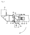
- FIG. 1 shows a cross-sectional view of a portion using the hinge member according to the present invention taken along line A-A in FIG. 3
- FIG. 2 is an explanatory cross-sectional view showing a condition where the door is opened
- FIG. 3 is a perspective view of a unit utilizing a hinge member of the present invention.
- FIG. 3 shows a unit 1 wherein a door is fixed to a door opening 11 using a hinge member 50 according to the present invention.
- the door opening 11 is formed to a wall member 13 of the unit 1.
- a door 10 is fixed rotatably to the opening 11.
- the door 10 is mounted to a corner panel 17 provided to the end edge of a side wall panel 15 through the hinge member 50.
- the hinge member 50 is provided with a support plate 51 for mounting to the corner panel 17 of the side wall panel 15, a hinge flange 53 for connecting to the door 10 side, and a pin 55 for rotatably connecting the support plate 51 and the hinge flange 53.
- the support plate 51 is a plate formed at one end with an insertion hole for inserting the pin 55, and is fixed to a corner channel 19 for covering the end edge of the corner panel 17.
- the corner channel 19 is comprised of a plate made of metal.
- the hinge flange 53 has a first hinge flange 53A having the longitudinal length size as a length size L, and a second hinge flange 53B connected to the first hinge flange 53A.
- the first hinge flange 53A is formed at one end with an insertion hole 531 for inserting the pin 55.
- the second hinge flange 53B forms a mounting portion 533 for mounting to the door 10.
- the mounting portion 533 for mounting to the door 10 is fixed to a supporting portion 113 provided to the end surface of the door 10 with a fixing member 60.
- the supporting portion 113 formed to the end surface of the door 10 is a closed cross-sectional member fitted to a concave groove formed within the thickness of the end surface of the door 10.
- the mounting portion 533 of the second hinge flange 53B has a cross-sectionally U-shaped fixing portion 535 fitted to the concave groove of the door 10, and the second hinge flange 53B is mounted to the end edge of the door 10 by matching the bottom of the fitting portion 535 to the supporting portion 113 and fixing the same by the fixing member 60.
- the door 10 is mounted to the corner channel 17 with a gap approximately the size of the length size L of the first hinge flange 53A, and rotates in the direction of arrow B centering around the hinge pin 55.
- the hinge member 50 of the present invention mounts the sealing member 70 within the U-shaped fitting portion 535 of the second hinge flange 53B.
- the sealing member 70 is composed by connecting a hollow convex portion 71 formed of elastic material made of synthetic resin and the like having flexibility, and a compressed portion 73 for fitting and compressing the fitting portion 535.
- the length size T of the ejecting hollow convex portion 71 of the sealing member 70 has a length size larger than the gap between the end edge of the door 10 and the corner panel 17, that is, the length size L of the first hinge flange 53A (size L ⁇ size T).
- the hollow convex portion 71 of the sealing member 70 corresponds to the external force by bending, and returns to the original shape when freed from the external force.
- the door 10 is mounted to the wall member such as the side wall panel 15 and the like so as to rotate from closed condition as is shown in FIG. 1 to the opened condition as is shown in FIG. 2 using the hinge pin 55 as the rotation axis.
- the door 10 Under the closed condition, the door 10 is mounted to the corner panel 17 with a gap the size of length size L of the first hinge flange 53A.
- the sealing member 70 is provided to the inner side of the gap portion. The inner side of the unit 1 is sealed, when the tip of the hollow convex portion 71 of the sealing member 70 bends by coming into contact with the corner channel 19 and sealing the gap between the door 10 and the corner panel 17. With the sealing member 70, air and light inside the room does not leak to the exterior. Also, with the gap corresponding to the size of the first hinge flange 53A existing between the door 10 and the corner panel 17, fear of injuring the user by pinching a finger and the like during operation of the door 10 could be eliminated. Moreover, when a hand, clothing and the like comes into contact with the hinge portion, such hand, clothing and the like will not be caught in the gap between the door 10 and the corner panel 17 with the existence of the sealing member 70.
- the present invention enables to eliminate the fear of a finger, an object or the like being caught in the hinge portion during operation of a moving body such as a door for entrance to structures such as a toiletry unit, a telephone booth and the like, and therefore, improvement in safety is achieved.
Landscapes
- Engineering & Computer Science (AREA)
- Mechanical Engineering (AREA)
- Civil Engineering (AREA)
- Structural Engineering (AREA)
- Specific Sealing Or Ventilating Devices For Doors And Windows (AREA)
- Hinges (AREA)
Applications Claiming Priority (2)
| Application Number | Priority Date | Filing Date | Title |
|---|---|---|---|
| JP2000005239A JP4014344B2 (ja) | 2000-01-05 | 2000-01-05 | ヒンジ部材 |
| JP2000005239 | 2000-01-05 |
Publications (3)
| Publication Number | Publication Date |
|---|---|
| EP1114906A2 true EP1114906A2 (de) | 2001-07-11 |
| EP1114906A3 EP1114906A3 (de) | 2003-04-23 |
| EP1114906B1 EP1114906B1 (de) | 2014-11-12 |
Family
ID=18533921
Family Applications (1)
| Application Number | Title | Priority Date | Filing Date |
|---|---|---|---|
| EP01100255.7A Expired - Lifetime EP1114906B1 (de) | 2000-01-05 | 2001-01-03 | Scharnierteil |
Country Status (3)
| Country | Link |
|---|---|
| US (1) | US6449802B2 (de) |
| EP (1) | EP1114906B1 (de) |
| JP (1) | JP4014344B2 (de) |
Cited By (1)
| Publication number | Priority date | Publication date | Assignee | Title |
|---|---|---|---|---|
| EP3348761A1 (de) * | 2017-01-13 | 2018-07-18 | Athmer OHG | Vorrichtung zur schwenkbaren befestigung eines türflügels an einer türzarge |
Families Citing this family (6)
| Publication number | Priority date | Publication date | Assignee | Title |
|---|---|---|---|---|
| US7296704B2 (en) * | 2004-08-11 | 2007-11-20 | Ferrini Jonathan B | Collapsible container |
| US20070028488A1 (en) * | 2005-07-19 | 2007-02-08 | Brad Bilinsky | Bracket and Method for Transport of Articulated Arm Attachment |
| KR101504505B1 (ko) * | 2013-12-06 | 2015-03-23 | 정태영 | 조립식 안전도어 |
| EP3879052A4 (de) * | 2018-11-05 | 2022-12-07 | The Yokohama Rubber Co., Ltd. | Gelenkstruktur für toilettentürkörper einer flugzeugtoiletteneinheit |
| AT521814B1 (de) * | 2018-11-13 | 2023-04-15 | Blum Gmbh Julius | Möbelscharnier |
| CA3111699A1 (en) * | 2020-03-10 | 2021-09-10 | Eckel Industries Of Canada Limited | Door hinge |
Family Cites Families (17)
| Publication number | Priority date | Publication date | Assignee | Title |
|---|---|---|---|---|
| US929615A (en) * | 1909-05-03 | 1909-07-27 | Frank V Madden | Hinge. |
| US1904120A (en) * | 1930-12-08 | 1933-04-18 | Bommer Emil | Door hinge |
| US2557716A (en) * | 1945-12-07 | 1951-06-19 | Moynahan Bronze Company | Safety hinge |
| FR1375473A (fr) * | 1963-11-22 | 1964-10-16 | Cloisons amovibles pour la formation ou la subdivision des pièces dans les bâtiments | |
| FR1602678A (de) * | 1968-08-19 | 1971-01-11 | ||
| FR2045014A5 (de) * | 1969-05-29 | 1971-02-26 | Servis | |
| US3911633A (en) * | 1974-07-22 | 1975-10-14 | Westerner Products Inc | Awning or patio cover mounting apparatus |
| US4064595A (en) * | 1976-09-07 | 1977-12-27 | The Knapheide Manufacturing Co. | Metal door and hinge construction |
| US4186460A (en) * | 1977-12-19 | 1980-02-05 | Artman J Clyde | Sleeper box hinge |
| US4807397A (en) * | 1987-10-05 | 1989-02-28 | Rjf International Corporation | Compression honeycomb door seal |
| US4864688A (en) * | 1988-05-23 | 1989-09-12 | Gerber Mary E | Hinge having varied height offset leafs |
| US5450694A (en) * | 1989-11-24 | 1995-09-19 | Silentia Ab | Movable screen partition |
| US5117587A (en) * | 1991-05-02 | 1992-06-02 | Rjf International Corporation | Sealing structure |
| US5220708A (en) * | 1992-04-01 | 1993-06-22 | Schlage Lock Company | Self-trimming shield for a door heel |
| AT399198B (de) * | 1993-08-23 | 1995-03-27 | Lindpointner Tore | Falt- oder schwingflügeltür |
| EP0729541B1 (de) * | 1993-11-19 | 1998-04-15 | Federal-Hoffman, Inc. | Scharniereinrichtung |
| US5448799A (en) * | 1994-09-26 | 1995-09-12 | Work Right Products, Inc. | Panel hinge |
-
2000
- 2000-01-05 JP JP2000005239A patent/JP4014344B2/ja not_active Expired - Lifetime
-
2001
- 2001-01-03 EP EP01100255.7A patent/EP1114906B1/de not_active Expired - Lifetime
- 2001-01-03 US US09/752,691 patent/US6449802B2/en not_active Expired - Lifetime
Cited By (4)
| Publication number | Priority date | Publication date | Assignee | Title |
|---|---|---|---|---|
| EP3348761A1 (de) * | 2017-01-13 | 2018-07-18 | Athmer OHG | Vorrichtung zur schwenkbaren befestigung eines türflügels an einer türzarge |
| EP3348760A1 (de) * | 2017-01-13 | 2018-07-18 | Athmer oHG | Vorrichtung zur schwenkbaren befestigung eines türflügels an einer türzarge |
| EP3511499A1 (de) * | 2017-01-13 | 2019-07-17 | Athmer OHG | Vorrichtung zur schwenkbaren befestigung eines türflügels an einer türzarge |
| EP3808926A1 (de) * | 2017-01-13 | 2021-04-21 | Athmer OHG | Vorrichtung zur schwenkbaren befestigung eines türflügels an einer türzarge |
Also Published As
| Publication number | Publication date |
|---|---|
| US20010005921A1 (en) | 2001-07-05 |
| US6449802B2 (en) | 2002-09-17 |
| EP1114906A3 (de) | 2003-04-23 |
| JP2001193336A (ja) | 2001-07-17 |
| JP4014344B2 (ja) | 2007-11-28 |
| EP1114906B1 (de) | 2014-11-12 |
Similar Documents
| Publication | Publication Date | Title |
|---|---|---|
| KR0169349B1 (ko) | 냉장고도어 개폐장치 | |
| US11306523B2 (en) | Pinch-preventing safety hinge for hinged door | |
| JP2520835Y2 (ja) | 折畳み扉の気密装置 | |
| US6449802B2 (en) | Hinge member | |
| SK286166B6 (sk) | Otočný spoj medzi odoberateľným a pevným dielom krytu | |
| CA2022324C (en) | Weather strip | |
| KR102244145B1 (ko) | 경첩의 힌지가 위치된 문의 후면 틈새를 가려주는 손끼임 방지 장치 | |
| JP3034509B2 (ja) | 電子レンジ用のドアの結合装置 | |
| JP5529864B2 (ja) | ドア組立体 | |
| JP7699020B2 (ja) | 収納式網戸及び建具 | |
| JPH11159260A (ja) | オペレータキャブ開閉窓のシール構造 | |
| KR102483324B1 (ko) | 도어와 문틀 사이의 틈새 전후방에 장착된 슬라이딩 작동형 손끼임 방지장치 | |
| KR200355903Y1 (ko) | 여닫이창용 키퍼 | |
| KR102754994B1 (ko) | 도어 클로저의 고정케이스 | |
| GB2202889A (en) | Sealing strips | |
| KR100585736B1 (ko) | 휴대용 단말기의 힌지장치 | |
| JP7699021B2 (ja) | 収納式網戸及び建具 | |
| KR102517976B1 (ko) | 도어 에지용 커버 조립체 | |
| JP7681483B2 (ja) | 収納式網戸及び建具 | |
| CN212390576U (zh) | 一种显示控制装置及具有其的空调器 | |
| JPS6339344Y2 (de) | ||
| JP2003002570A (ja) | エレベーターの戸当り装置 | |
| KR200266092Y1 (ko) | 일자형 미세기 창의 방충망 장치 | |
| JP2001342777A (ja) | ドア装置 | |
| KR0127377Y1 (ko) | 건물용 셔터의 비상문 경첩장치 |
Legal Events
| Date | Code | Title | Description |
|---|---|---|---|
| PUAI | Public reference made under article 153(3) epc to a published international application that has entered the european phase |
Free format text: ORIGINAL CODE: 0009012 |
|
| AK | Designated contracting states |
Kind code of ref document: A2 Designated state(s): AT BE CH CY DE DK ES FI FR GB GR IE IT LI LU MC NL PT SE TR |
|
| AX | Request for extension of the european patent |
Free format text: AL;LT;LV;MK;RO;SI |
|
| PUAL | Search report despatched |
Free format text: ORIGINAL CODE: 0009013 |
|
| AK | Designated contracting states |
Designated state(s): AT BE CH CY DE DK ES FI FR GB GR IE IT LI LU MC NL PT SE TR |
|
| AX | Request for extension of the european patent |
Extension state: AL LT LV MK RO SI |
|
| RIC1 | Information provided on ipc code assigned before grant |
Ipc: 7E 05D 5/06 A Ipc: 7E 06B 7/16 B Ipc: 7E 06B 7/36 B Ipc: 7E 05D 11/00 B |
|
| 17P | Request for examination filed |
Effective date: 20030711 |
|
| AKX | Designation fees paid |
Designated state(s): DE FR GB NL |
|
| 17Q | First examination report despatched |
Effective date: 20071227 |
|
| GRAP | Despatch of communication of intention to grant a patent |
Free format text: ORIGINAL CODE: EPIDOSNIGR1 |
|
| INTG | Intention to grant announced |
Effective date: 20140714 |
|
| RIN1 | Information on inventor provided before grant (corrected) |
Inventor name: MAEDA, SHUJI JAMCO CORPORATION |
|
| GRAS | Grant fee paid |
Free format text: ORIGINAL CODE: EPIDOSNIGR3 |
|
| GRAA | (expected) grant |
Free format text: ORIGINAL CODE: 0009210 |
|
| AK | Designated contracting states |
Kind code of ref document: B1 Designated state(s): DE FR GB NL |
|
| REG | Reference to a national code |
Ref country code: GB Ref legal event code: FG4D |
|
| RIN1 | Information on inventor provided before grant (corrected) |
Inventor name: MAEDA, SHUJI |
|
| REG | Reference to a national code |
Ref country code: DE Ref legal event code: R096 Ref document number: 60149097 Country of ref document: DE Effective date: 20141224 |
|
| REG | Reference to a national code |
Ref country code: NL Ref legal event code: VDEP Effective date: 20141112 |
|
| PG25 | Lapsed in a contracting state [announced via postgrant information from national office to epo] |
Ref country code: NL Free format text: LAPSE BECAUSE OF FAILURE TO SUBMIT A TRANSLATION OF THE DESCRIPTION OR TO PAY THE FEE WITHIN THE PRESCRIBED TIME-LIMIT Effective date: 20141112 |
|
| REG | Reference to a national code |
Ref country code: DE Ref legal event code: R097 Ref document number: 60149097 Country of ref document: DE |
|
| PLBE | No opposition filed within time limit |
Free format text: ORIGINAL CODE: 0009261 |
|
| STAA | Information on the status of an ep patent application or granted ep patent |
Free format text: STATUS: NO OPPOSITION FILED WITHIN TIME LIMIT |
|
| 26N | No opposition filed |
Effective date: 20150813 |
|
| GBPC | Gb: european patent ceased through non-payment of renewal fee |
Effective date: 20150212 |
|
| REG | Reference to a national code |
Ref country code: FR Ref legal event code: PLFP Year of fee payment: 16 |
|
| PG25 | Lapsed in a contracting state [announced via postgrant information from national office to epo] |
Ref country code: GB Free format text: LAPSE BECAUSE OF NON-PAYMENT OF DUE FEES Effective date: 20150212 |
|
| REG | Reference to a national code |
Ref country code: FR Ref legal event code: PLFP Year of fee payment: 17 |
|
| REG | Reference to a national code |
Ref country code: FR Ref legal event code: PLFP Year of fee payment: 18 |
|
| PGFP | Annual fee paid to national office [announced via postgrant information from national office to epo] |
Ref country code: FR Payment date: 20191216 Year of fee payment: 20 |
|
| PGFP | Annual fee paid to national office [announced via postgrant information from national office to epo] |
Ref country code: DE Payment date: 20191224 Year of fee payment: 20 |
|
| REG | Reference to a national code |
Ref country code: DE Ref legal event code: R071 Ref document number: 60149097 Country of ref document: DE |