EP1114731A2 - Drucksystem - Google Patents
Drucksystem Download PDFInfo
- Publication number
- EP1114731A2 EP1114731A2 EP00311178A EP00311178A EP1114731A2 EP 1114731 A2 EP1114731 A2 EP 1114731A2 EP 00311178 A EP00311178 A EP 00311178A EP 00311178 A EP00311178 A EP 00311178A EP 1114731 A2 EP1114731 A2 EP 1114731A2
- Authority
- EP
- European Patent Office
- Prior art keywords
- media
- front wall
- bezel
- cassette
- input tray
- Prior art date
- Legal status (The legal status is an assumption and is not a legal conclusion. Google has not performed a legal analysis and makes no representation as to the accuracy of the status listed.)
- Granted
Links
Images


Classifications
-
- B—PERFORMING OPERATIONS; TRANSPORTING
- B41—PRINTING; LINING MACHINES; TYPEWRITERS; STAMPS
- B41J—TYPEWRITERS; SELECTIVE PRINTING MECHANISMS, i.e. MECHANISMS PRINTING OTHERWISE THAN FROM A FORME; CORRECTION OF TYPOGRAPHICAL ERRORS
- B41J29/00—Details of, or accessories for, typewriters or selective printing mechanisms not otherwise provided for
- B41J29/02—Framework
- B41J29/023—Framework with reduced dimensions
-
- B—PERFORMING OPERATIONS; TRANSPORTING
- B41—PRINTING; LINING MACHINES; TYPEWRITERS; STAMPS
- B41J—TYPEWRITERS; SELECTIVE PRINTING MECHANISMS, i.e. MECHANISMS PRINTING OTHERWISE THAN FROM A FORME; CORRECTION OF TYPOGRAPHICAL ERRORS
- B41J13/00—Devices or arrangements of selective printing mechanisms, e.g. ink-jet printers or thermal printers, specially adapted for supporting or handling copy material in short lengths, e.g. sheets
- B41J13/10—Sheet holders, retainers, movable guides, or stationary guides
- B41J13/106—Sheet holders, retainers, movable guides, or stationary guides for the sheet output section
-
- B—PERFORMING OPERATIONS; TRANSPORTING
- B41—PRINTING; LINING MACHINES; TYPEWRITERS; STAMPS
- B41J—TYPEWRITERS; SELECTIVE PRINTING MECHANISMS, i.e. MECHANISMS PRINTING OTHERWISE THAN FROM A FORME; CORRECTION OF TYPOGRAPHICAL ERRORS
- B41J29/00—Details of, or accessories for, typewriters or selective printing mechanisms not otherwise provided for
- B41J29/02—Framework
- B41J29/026—Stackable
Definitions
- the present invention relates generally to a printer, a media cassette and method of mounting a bezel on a media cassette and, for example to a hard copy document apparatus and method of using the apparatus and, more particularly, for a stackable low profile Internet appliance printer.
- the cable box has the built-in capabilities of not only providing television programming displayed on a "cinema size" projection screen but also Internet accesses through a built-in Internet access module and remote keyboard.
- the size of the typical cable box has been configured to fit within the family entertainment centre and thus such an integrated solution has been somewhat successful for viewing Internet content but not fulfilling the .com Internet commercial activities.
- a new and improved computer printer that can be easily integrated into a family entertainment centre in an aesthetically pleasing manner.
- Such a new and improved printer should be stackable with the other electronic components found in the entertainment centre and should be easy to use, including the changing of printhead cartridges, changing media and clearing the printer of any media jams.
- the present invention seeks to provide an improved printer.
- the preferred embodiment provides a low profile stackable Internet appliance printer having a removable combination input/output tray cassette with a removable bezel.
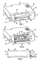
- low profile Internet appliance printer 10 which is stackable in an electronics cabinet 12 with other electronic components such as a cable box 14 and a digital video device 16.
- the printer 10 includes Internet electronics and a modem (not shown) an thus, is adapted for use with a monitor 18 to enable a user to print desired images and information associated with the information displayed on the monitor 18.
- the low profile Internet appliance printer 10 will be referred to hereinafter as simply "the printer”.
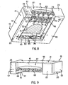
- the printer 10 is modular in nature and generally comprises a set of assemblies as best seen in FIG. 4 that include a base chassis assembly 20 for supporting from below a low profile print bar assembly 22 and a low profile service station assembly 24.
- a media cassette assembly 26 is slidably mounted within the base assembly 20 for holding simultaneously a supply of input media and individual sheets of output media until the output media is retrieved by a user (not shown).
- the base chassis assembly 20 further supports at a rear portion thereof a motor driven paper pick assembly 60 for facilitating the picking of individual sheets of input media from an input tray 32 forming part of the media cassette assembly 26 and for driving the individual picked sheets along a short paper path P through a print zone 17.
- a motor driven drive roller assembly 61 mounted at a front portion of the base chassis assembly 20, pulls the individual sheets that have passed through the print zone 17 a further distance along the paper path P so that individual ones of the sheets of media can be ejected into an output tray 34 that also forms part of the media cassette assembly 26.
- An electronic assembly 30 is also mounted to the base assembly 20 for helping to facilitate the moving of the media along the paper path P and for helping to facilitate the ejecting of ink in a desired pattern onto individual ones of the media sheets as they pass through the print zone 17.
- a housing 19 covers the assemblies 20, 22, 24, and 30 when they are integrated into a single unit.
- the housing 19 as best seen in FIG. 1 includes a set of outer skin members: a four-sided main skin member 21, a right front skin member 23, a left front skin member 25 and a bottom plate member 45 (FIG. 7) each of which is mounted to the base chassis assembly 20 to provide the printer 10 with an overall box-like configuration.
- the main skin member 21 has a unitary construction and includes a left side portion 51, a right side portion 52, a rear portion 53 and a top portion 55 each having a generally smooth planar surface to provide the printer 10 with a pleasing aesthetic appearance.
- the low profile printer 10 has an upper front passageway indicated generally at 13 and a lower front passageway indicated generally at 15.
- the upper passageway 13 is covered with an access door 27 having an overall L-shaped configuration.
- the access door 27 includes a front face member 41 and a top member 48 that are integrally connected at about an angle of ninety degrees as best seen in FIG. 3.
- the access door 27 is pivotally mounted above the lower passageway 15 and extends laterally between the right skin member 23 and the left skin member 25.
- the front face member 41 is disposed flush to the interior side edges of the side skin members 23 and 25 to provide the printer 10 with a pleasing aesthetic appearance.
- the top member 48 is disposed in an abutting relationship with a front top edge of the top 55 of the main skin 21 and the top interior side edges of the right skin 23 and the left skin 25 to further provide the printer 10 with a pleasing aesthetic appearance.
- an access space indicated generally at 49 is formed when the access door 27 is moved to an open position as illustrated in FIG. 2.
- a low profile carriage assembly 36 that forms part of the low profile printer assembly 22.
- the carriage assembly 36 includes a pair of print cartridge stalls 37 and 38 for holding in a secure manner disposable print head cartridges, such as the cartridges 39 and 40.
- the access space 49 in the top front of the printer 10 permits or allows a user to easily grasp either of the cartridges 39 or 40 for installation or removal purposes from their respective stalls 37 and 38. Such installation or removal of cartridges is made possible even when the printer 10 is stacked beneath other electronic components, such as the electronic components 14 and 16 as illustrated in FIG. 11. In short then, front loading and unloading of print head cartridges 39 and 40 is made possible in the low profile design of the printer 10.
- a media output slot indicated generally at 29 is disposed adjacent a set 31 of drive rollers to permit media to pass, via the set 31 of drive rollers from the interior print zone 17 through the media output slot 29 into the output tray 34.
- a set 33 of guides are mounted the interior surface of a front face member 41 of the access door 27 and cooperate with the set 31 of drive rollers to help facilitate the guiding and directing of individual sheets of media toward the output tray 34.
- the access door 27 is mounted between a right side chassis member 42 and a left side chassis member 44 that form part of the chassis assembly 20.
- the right side chassis member 42 supports the service station assembly 24, while the left side chassis supports a combination user interface and power control module that includes a set 57 of switches, light control diodes and infrared sensors that extend through the left side skin member 25 20 so they are visible to a user.
- the front access door 27 also facilitates the closing of the upper front passageway 13, so that the detectable internal sounds produced by the printer 10 when printing are substantially reduced.
- the base chassis assembly 20 is box like, has a generally rectangular shape and includes a rear chassis assembly 43 that is interconnected between the right side chassis assembly 42 and the left side chassis assembly 44.
- the bottom or base plate 45 has a unitary construction and is generally U-shaped. The bottom plate 45 is mounted to the bottom of the base chassis assembly 20 so that the underside of the printer 10 is provided with a planar configuration.
- a right side slide rail 46 (FIG. 5) and a left side slide rail 47 (FIG. 7) are formed at the base of the right side chassis 42 and the left side chassis 44 respectively.
- the rails 46 and 47 are configured to receive and support the cassette 26 when the cassette 26 is slidably mounted thereon.
- the lower passageway 15 as seen in a bottom plan view of the printer 10 is U-shaped and is dimensioned for receiving therein the media cassette assembly 26.
- the passageway 15 is also U-shaped and is disposed in substantial parallel plane alignment with a front face portion 41 of the front door 27.
- a channel or stop 35 is set back from the entrance to the passageway 15 and is mounted between the right side chassis member 42 and the left side chassis member 44.
- the stop 35 engages a front wall 110 (FIG. 6) of the cassette assembly 26 to limit or stop it from further travel within the passageway 15.
- the cassette assembly 26 travels within the passageway 15 riding on the rail members 46 and 47 that form part of the right side chassis member 42 and the left side chassis member 44 respectively.
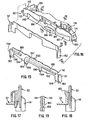
- the media cassette assembly 26 is a combination input/output tray cassette unit that is completely removable from the printer 10.
- the assembly 26 includes both the input tray 32 for receiving and holding media, such as paper, for printing thereon, and the output tray 34 for receiving and holding media after it has been printed thereon.
- the single cassette 26 holds both the media for printing on and the media printed on after passing through the printer 10.
- a large rectangular shaped channel member 70 (FIG. 10) is disposed within this space mounted between the right side chassis 42 and the left side chassis 44 and extends between the rear pick roller assembly 60 and a set 68 of drive rollers (DR) forming part of the front drive roller assembly 61.
- DR drive rollers
- a large cut-out 71 provided in the channel manner 70 coupled with the large space that results in the underside of the printer 10 when the cassette assembly 26 is removed therefrom, provides a means for a user to clear and remove any media that might accidentally become jammed within the interior media path P of the printer 10.
- the access to the interior of the printer 10 from the passageway 15 via the cut-out 71 permits the printer 10 to be stacked with other electronic components as best seen in FIG. 12.
- the cassette assembly 26 is of a generally rectangular shape having the front wall 110, a bottom wall or floor 112, a pair of side walls 114 and 116 respectively, and a back or end wall 118.
- the front, rear and side walls of the cassette 26 are generally of the same height and form a large space indicated generally at 120.
- the space 120 is sufficiently large for receiving both United States standard A size media (8 1/2-inch by 11-inch paper) as well as the narrow and longer A4 paper.
- a moveable pressure plate 117 is disposed at a rear portion of the cassette 26 for helping to facilitate the picking of media from the input tray.
- the side walls 114 and 116 provide a stair step shape configuration with the bottom portion of the walls being recessed inwardly from the top portion of the walls 114 and 116.
- a set of guides such as a guide 121, projects outwardly from the bottom portion of each side wall 114, 116 and are spaced apart from one another.
- the guides 121 cooperate with the top portions of the side walls 114 and 116 to form rail-receiving channels therebetween to receive the rails 46 and 47 respectively.
- An output tray receiving slot or opening indicated generally at 127 is formed in the front wall 110.
- the slot 127 is dimensioned for receiving therein the output tray 34.
- the slot 127 extends beneath the floor 112.
- the output tray 34 is supported within the slot 127 by a set of spaced apart rails (not shown) that are disposed on the interior surfaces of the bottom portions of the side walls 114 and 116 respectively.
- the top surface area of the bottom floor 112 is about equal to the surface area of the top surface of the output tray 34.
- the area of the space 120 and that portion of the space 120 that is utilised for accommodating the different sizes of media is larger in overall area than the output tray 34.
- the output tray 34 has an area size that is between about two-thirds to three-fourth the overall area size of the space 120.
- the input tray 32 includes an output width adjuster slide assembly 130 and a paper length adjuster or slide 132 that help facilitate the loading and discharge of different sized media from the printer 10.
- the assembly 130 engages a kick out plate adjuster pin 160 (FIG. 7) to facilitate the proper discharge of media into the output tray 34.
- the paper length adjuster slide 132 includes a media engaging tab 134 that travels in an opening 136 disposed in the floor 112.
- the tab 134 is movable between two different size setting: an A-4 media size setting position as best seen in FIG. 6 and an A-1 media size setting as best seen in FIG. 5.
- the first setting size as best seen in FIG. 5
- the side edges of the media are engaged between the interior of the side wall 114 and an interior wall portion of a slide member 138 that forms part of the output width adjuster 130.
- the top edge of the media engages the face of the slide member 138 while the bottom edge engages the back wall 118.
- the second setting size as best seen in FIG.
- the side edges of the media are engaged between the interior of the side wall 114 and the interior wall of the slide member 138.
- the top edge of the media engages the face of the slide member 134 (which has now been positioned to the second size position) while the bottom edge of the media engages the back wall 118.
- the output width adjuster slide assembly 130 is moveable between two different size settings in a similar manner as the paper length adjuster slide 132.
- the operation of the output width adjuster slide assembly 130 will be described hereinafter in greater detail. From the foregoing it should be understood by those skilled in the art that different sizes of media are accommodated within the space 120 by the adjustment of the slides 130 and 132, and that the slides 130 and 132 cooperate with the side wall 114 and the back wall 118 to form a proper size input tray cassette having a generally rectangular shape.
- the output tray 34 is slidably mounted within the cassette 26 so that it can be telescopically extended and retracted. When extended, the output tray 34 has a sufficient dimension to support either a standard A-1, 8 1/2 by 11-inch media sheet or an A4 media sheet, which sizes are the same as can be held within the input tray 32.
- the output tray 34 has a unitary construction and includes a base member 144 having a set of spaced apart rib or riser members indicated generally at 140 and 142 respectively which are integrally attached to a top surface thereof.
- the rib members 140 and 142 are constructed simultaneously to engage the front wall 110 of the cassette 26 when the output tray 34 is pull telescopically outward from the cassette 26. In this manner, the risers 140 and 142 stop the outward travel of the output tray 34 positioning the output tray 34 in a proper position for supporting from below sheets of media as they are driven out of the printer 10 by the set 31 of drive rollers.
- the riser members 140 and 142 are substantially identical in construction, only the riser members 140 will be described in greater detail.
- the riser members 140 include four spaced apart risers, such as a riser 141.
- the riser 141 has a narrow elongated construction that extends upwardly a sufficient distance from a front or proximate end thereof toward a rear or distal end to engage the underside of the front wall 110 of the cassette 26. In this manner when the riser 141 engages the underside of the front wall 110 the forward travel of the output tray extending outwardly from the cassette 26 is inhibited.
- the riser members 140 and 142 because of their orientation on opposite sides of the output tray 34, interlock the underside of the front wall 110 at about the end of the path of travel followed by the output tray 34, allowing the output tray to slide easily through most of its motion and yet tilt at about a zero degree to about a two degree angle at the end of its travel motion to facilitate the capture and holding of output media discharged from the printer 10.
- the output tray 34 further includes an opening 145 that is disposed adjacent to a front edge 146 of the output tray and between a pair of wedge members 147 and 148 respectively.
- the opening 145 functions as a gripping handle that can be grasped by a user to pull the output tray 34 outwardly from the cassette 26.
- the wedge members 147 and 148 slope upwardly from the upper surface of the base 144 reaching their maximum height at the respective front corners of the output tray. In this manner the edge members 147 and 148 function as stops to limit the forward travel of the media sheets as they are driven in seriatim from the printer 10 so that the media sheets are stacked on the upper surface of the base 144.
- the cassette 26 In use, when the cassette 26 is inserted into the passageway 15, the cassette 26 is fully received within the printer 10 without the output tray 34 extending beyond the front face of the printer 10. The cassette 26 slides along the rails 46 and 47 until a front wall member 110 thereof engages the channel stop 35. When the cassette 26 is pulled out from the passageway 15, tile cassette 26 travels in a reverse direction along the rails 46, 47 until a stop member 123 of a right side wall 114 of the cassette engages a backside of the channel stop 35. As will be explained hereinafter in greater detail, the right side wall 114 includes an elongated flexible extension 125 that can be depressed by the user to release the stop 123 from engagement with the channel stop 35.
- the extension 125 is integrally attached at its proximate end to the main body portion of the side wall 114 and has a narrow concave configuration at its distal end to help a user locate that potion of the extension that needs to be pressed to release the cassette 26 from the lower passageway 15.
- the cassette 26 can continue its reverse path of travel under the force of the user, allowing the cassette 26 to be completely removed from the printer 10. From the foregoing, it should be understood by those skilled in the art, that the cassette 26 can be moved a sufficient distance out from the interior of the printer 10 to allow the cassette 26 to be filled or refilled with a desired type of media. Furthermore, the cassette 26 can be completely removed from the printer to give the user access to the interior of the printer 10 via the access passageway 15 and the cut-out 71. In this manner, the clearing of paper jams is facilitated while the printer 10 remains in a stacked orientation with other electronic components as best seen in FIG. 7
- the bezel 50 has a unitary construction that generally includes a left side wall member 199, a right side wall member 198 and a central wall member 200.
- the respective ones of the side wall members 198 and 199 have cut-outs that are sufficiently large to permit the output tray 34 to pass therethrough.
- Integrally connected and extending perpendicular to the side walls 198 and 199 are a pair of wing members 190 and 191.
- the bezel 50 is mounted removably to the front wall 110 and the side walls 114 and 116 for providing the cassette 26 with a pleasing aesthetic appearance.
- a right side snap or projection 180 and a left side snap 181 extend outwardly from the lower portions of the side walls 114 and 116 respectively at their lower distal ends adjacent to the front wall.
- a pair of snap engaging openings 182 and 183 are provided for engaging the side wall snaps 180 and 181.
- the openings 182 and 183 are disposed in the lower portions of the wing members 190 and 191 respectively.
- the bezel 50 also includes a pair of spaced apart fixing pins 184 and 185 that are dimensioned for sliding engagement with a corresponding pair of centrally disposed pin holes 186 and 187 (FIG. 16) disposed in the cassette 26 at the front wall 110 thereof.
- the pins 184 and 185 form part of a boss 197 that projects outwardly from the central wall 200.
- An opening is formed in the boss 197 and is defined by two interior walls 195 and 196.
- a pair of spaced apart overhangs 188 and 189 is disposed on the rear face of the bezel 50.
- the top edge portion of the front wall 110 supports from below the overhangs 188 and 189.
- the front wall 110 of the cassette assembly 26 includes a centrally disposed rectangular shaped recess 190.
- the recess 190 is disposed opposite the opening 145 to help prevent the fingers of the user from engaging the front wall when the user pulls the output tray 34 outwardly.
- a semi-elliptical cut-out 192 is disposed in the centre of the recess 190 to provide an observation window or frame to the interior of the input tray 32.
- the semi-elliptical cut-out 192 is wider at its base adjacent the output tray than at its top adjacent the top of the recess 190. In this manner, the user is able to have a greater view of a low supply of media than a lull supply of media.
- the channel member 70 is mounted between the rear pick roller assembly 60 and the rear set 68 of drive rollers (DR) forming part of the front drive roller assembly 61.
- the channel member 70 is disposed within the passageway 15 such that the upper surface of the channel member is in a parallel plane with the nips of the set 68 of rear drive rollers (DR) so that media passing along the top surface of the channel member 70 is directed into the nips of the drive rollers.
- the front of the channel member 70 includes a plurality of notched cut-outs 72-75 that are dimensioned to be slightly larger in width than individual ones of the drive rollers DR of the drive roller assembly 61.
- a front edge portion 81 of the channel member 70 is mounted in adjacent abutment to the rollers DR without making direct contact with the rollers or the drive shaft 62 of the drive roller assembly 61.
- Centrally disposed openings, such as the openings 76-79 are disposed opposite each one of the notched cut-outs 72-75 and spaced from the central cut-out 71. The openings 76-79 provide further access to the paper path.
- Another set of notched cutest 81-83 are disposed at the rear portion of the channel member 70.
- the notched cut-outs 81-83 are dimensioned to be slightly larger in width than individual ones of the pick rollers PR of the pick roller assembly 60.
- a rear edge portion 84 of the channel member 70 is mounted in adjacent abutment to the pick rollers PR without making contact the pick rollers PR of their associated drive shaft 85.
- the cut-out 71 has a generally elliptical shape with a wide base indicated generally at 86 and a narrow top indicated generally at 87.
- the cut-out 71 is centrally disposed within the channel member 70 and spaced from the front notched cut-outs 72-75 and the rear notched cut-outs 81-83.
- the cut-outs 71, and 72-75, and 81-83 in combination provide a substantially open paper path that facilitates the easy removal of substantially any paper jam without the need of the user lifting the printer 10 from its supporting surface.
- the printer 10 includes a kick out plate assembly 58 (FIG. 14).
- the kick out plate assembly 58 generally comprises a platen or ribbed kicked out plate 59 that is mounted between the rear set 68 and the front set 69 of drive rollers and extends between the right side chassis 42 and the left side chassis 44.
- the kick out plate 59 has a set 63 of upstanding rib members (RM) that help guide the output media through the media output slot 29 toward the output tray 34.
- RM upstanding rib members
- the kick out plate 59 includes at its back edge a series of spaced apart cut-outs 64-67 that are dimensioned to allow the kick out plate 59 to be mounted adjacent the set 68 of the drive rollers forming part of the drive roller assembly.
- the kick out plate 59 also includes at its front edge a series of spaced apart cut-outs 91-95 that are dimensioned to allow the kick out plate 59 to be mounted adjacent the front set 69 of the drive rollers forming part of the drive roller assembly.
- a large cut-out 96 is disposed next to cut-out 95 and is dimensioned for receiving therein an output edge slide 97 that forms part of the output width adjuster slide assembly 130.
- the assembly 130 generally includes the input tray slide member 138 that is disposed in the input tray 32, a pin assembly 104 that is mounted at a distal end of the media output slot 29 above the kick out plate 59 and the output edge slide 97.
- the pin assembly 104 includes a finger-engaging unit 106 that supports from above the kick out plate adjuster pin 160.
- the pin 160 extends perpendicularly down from the finger engaging unit 106 passing through an adjustment hole 108 disposed in the kick out plate 58 and a corresponding hole 109 disposed in the channel member 35.
- the pin 160 has a sufficient length so that its distal free end is disposed within the interior of input tray 32 when the cassette 26 is mounted in the printer 10.
- the user when the user adjusts the paper length adjuster 132 for A4 size media, the user also adjusts the finger engaging unit 104 for A4 media by sliding the unit 104 into a proper A4 position. The stack 194 of A4 size media is then placed in the input tray 32.
- the pin 160 engages a cam surface 126 that causes the slide 138 to be pushed rearwardly along its first path of travel.
- the slide 138 is pushed rearwardly, its distal end furthest from the pin 160 engages another cam surface 128 causing the slide to move in a horizontal direction.
- a slide plate 129 integrally attached to the slide 102 moves into engagement with the floor 112 narrowing the width distance between the slide 138 and the side wall 114. The narrow width is sufficient for A4 size media.
- the pin 160 When the slide unit 138 is positioned for United States A size paper, the pin 160 is unable to engage the cam surface 126. It should be noted that since the pin passes through the hole 108 in slide 97, the slide 97 is automatically positioned providing the proper kick out for media passing through the media output slot 29. In short then, the output edge slide 97 is moveable between two positions within the cut-out 96: an A4 size position as seen in solid line in FIG. 14 and in an A size position as seen in dash line in FIG 14.
Landscapes
- Sheets, Magazines, And Separation Thereof (AREA)
- Pile Receivers (AREA)
- Accessory Devices And Overall Control Thereof (AREA)
- Ink Jet (AREA)
Applications Claiming Priority (2)
| Application Number | Priority Date | Filing Date | Title |
|---|---|---|---|
| US09/477,930 US6322264B1 (en) | 2000-01-05 | 2000-01-05 | Media cassette having an upper input tray and a lower output tray |
| US477930 | 2000-01-05 |
Publications (3)
| Publication Number | Publication Date |
|---|---|
| EP1114731A2 true EP1114731A2 (de) | 2001-07-11 |
| EP1114731A3 EP1114731A3 (de) | 2002-06-12 |
| EP1114731B1 EP1114731B1 (de) | 2003-10-08 |
Family
ID=23897901
Family Applications (1)
| Application Number | Title | Priority Date | Filing Date |
|---|---|---|---|
| EP00311178A Expired - Lifetime EP1114731B1 (de) | 2000-01-05 | 2000-12-14 | Drucksystem |
Country Status (5)
| Country | Link |
|---|---|
| US (1) | US6322264B1 (de) |
| EP (1) | EP1114731B1 (de) |
| JP (1) | JP2001191611A (de) |
| DE (1) | DE60005777T2 (de) |
| TW (1) | TW505567B (de) |
Cited By (3)
| Publication number | Priority date | Publication date | Assignee | Title |
|---|---|---|---|---|
| EP1375170A1 (de) * | 2002-06-21 | 2004-01-02 | Hewlett-Packard Development Company, L.P. | Rekonfigurierbare Frontplatte, Bausatz und Verfahren |
| WO2007102121A2 (en) | 2006-03-06 | 2007-09-13 | Bematech S.A. | Printer with modular cartridge |
| US7936366B2 (en) | 2006-03-06 | 2011-05-03 | Bematech Industria E Comercio De Equipamentos Electronics S/A | Thermal printer |
Families Citing this family (4)
| Publication number | Priority date | Publication date | Assignee | Title |
|---|---|---|---|---|
| US6536968B2 (en) * | 2000-12-01 | 2003-03-25 | Hewlett-Packard Company | Paper tray for a printer |
| JP2007119233A (ja) * | 2005-10-31 | 2007-05-17 | Brother Ind Ltd | 画像記録装置 |
| JP5071515B2 (ja) * | 2010-04-22 | 2012-11-14 | ブラザー工業株式会社 | 画像形成装置 |
| US9365058B2 (en) | 2012-09-26 | 2016-06-14 | Hewlett-Packard Development Company, L.P. | Printer paper tray |
Citations (4)
| Publication number | Priority date | Publication date | Assignee | Title |
|---|---|---|---|---|
| EP0492638A2 (de) * | 1990-12-28 | 1992-07-01 | Canon Kabushiki Kaisha | Aufzeichnungssystem mit automatischem Blattversorgungsapparat |
| US5692231A (en) * | 1995-07-24 | 1997-11-25 | Samsung Electronics Co. Ltd. | Image forming system for enabling detection of the quantity of sheets remaining in a sheet cassette |
| US5746528A (en) * | 1997-02-26 | 1998-05-05 | Hewlett-Packard Company | Hard copy apparatus with a print media telescoping tray system |
| US5768370A (en) * | 1997-01-08 | 1998-06-16 | Nokia Mobile Phones, Ltd. | User changeable cosmetic phone interface |
Family Cites Families (4)
| Publication number | Priority date | Publication date | Assignee | Title |
|---|---|---|---|---|
| US4698650A (en) * | 1984-03-28 | 1987-10-06 | Canon Kabushiki Kaisha | Recording apparatus and cassette for recording medium |
| US4847632A (en) * | 1988-06-03 | 1989-07-11 | Polaroid Corporation | Printer apparatus having foldable catcher assembly |
| US6120201A (en) * | 1999-07-12 | 2000-09-19 | Hewlett-Packard Company | Printer with front portion providing access to print mechanism |
| US6132122A (en) * | 1999-08-23 | 2000-10-17 | Hewlett-Packard Company | Low profile architecture for internet appliance printing |
-
2000
- 2000-01-05 US US09/477,930 patent/US6322264B1/en not_active Expired - Fee Related
- 2000-09-15 TW TW089118968A patent/TW505567B/zh not_active IP Right Cessation
- 2000-11-29 JP JP2000362250A patent/JP2001191611A/ja not_active Withdrawn
- 2000-12-14 EP EP00311178A patent/EP1114731B1/de not_active Expired - Lifetime
- 2000-12-14 DE DE60005777T patent/DE60005777T2/de not_active Expired - Fee Related
Patent Citations (4)
| Publication number | Priority date | Publication date | Assignee | Title |
|---|---|---|---|---|
| EP0492638A2 (de) * | 1990-12-28 | 1992-07-01 | Canon Kabushiki Kaisha | Aufzeichnungssystem mit automatischem Blattversorgungsapparat |
| US5692231A (en) * | 1995-07-24 | 1997-11-25 | Samsung Electronics Co. Ltd. | Image forming system for enabling detection of the quantity of sheets remaining in a sheet cassette |
| US5768370A (en) * | 1997-01-08 | 1998-06-16 | Nokia Mobile Phones, Ltd. | User changeable cosmetic phone interface |
| US5746528A (en) * | 1997-02-26 | 1998-05-05 | Hewlett-Packard Company | Hard copy apparatus with a print media telescoping tray system |
Cited By (7)
| Publication number | Priority date | Publication date | Assignee | Title |
|---|---|---|---|---|
| US6899422B2 (en) | 2001-10-26 | 2005-05-31 | Hewlett-Packard Development Company, L.P. | Reconfigurable panel, assembly, and method |
| EP1375170A1 (de) * | 2002-06-21 | 2004-01-02 | Hewlett-Packard Development Company, L.P. | Rekonfigurierbare Frontplatte, Bausatz und Verfahren |
| WO2007102121A2 (en) | 2006-03-06 | 2007-09-13 | Bematech S.A. | Printer with modular cartridge |
| EP1991426A2 (de) * | 2006-03-06 | 2008-11-19 | Bematech S.A. | Drucker mit modularer patrone |
| EP1991426A4 (de) * | 2006-03-06 | 2010-05-05 | Bematech S A | Drucker mit modularer patrone |
| US7936366B2 (en) | 2006-03-06 | 2011-05-03 | Bematech Industria E Comercio De Equipamentos Electronics S/A | Thermal printer |
| US8425130B2 (en) | 2006-03-06 | 2013-04-23 | Bematech S.A. | Printer with modular cartridge |
Also Published As
| Publication number | Publication date |
|---|---|
| EP1114731A3 (de) | 2002-06-12 |
| TW505567B (en) | 2002-10-11 |
| DE60005777D1 (de) | 2003-11-13 |
| EP1114731B1 (de) | 2003-10-08 |
| DE60005777T2 (de) | 2004-07-29 |
| US6322264B1 (en) | 2001-11-27 |
| JP2001191611A (ja) | 2001-07-17 |
Similar Documents
| Publication | Publication Date | Title |
|---|---|---|
| EP1114728B1 (de) | Stapelbarer Drucker und Verfahren zu seiner Verwendung | |
| EP1114730B1 (de) | Medienablagenhalter und Verfahren zu seiner Benutzung | |
| EP1114729B1 (de) | Drucker mit flacher Kontur und mit offenem unterem Papierpfad | |
| US20120081489A1 (en) | Tray unit and image recording device | |
| EP1114727B1 (de) | Stapelbarer Drucker mit niedrigem Profil | |
| EP1114731B1 (de) | Drucksystem | |
| US6290409B1 (en) | Media observation frame and method of using same | |
| US6249295B1 (en) | Recording apparatus with self-standing recording unit and sheet supplying apparatus | |
| JPH10120196A (ja) | 給紙カセット | |
| JPH04226773A (ja) | 記録装置 | |
| JP2004323163A (ja) | 画像形成装置 | |
| JP3080177B2 (ja) | 自動給紙装置 | |
| JP2855373B2 (ja) | 自動給紙装置 | |
| JPH04251035A (ja) | 自動給紙装置 | |
| JPH07267471A (ja) | プリンタ装置 | |
| JP2001122469A (ja) | シート給送装置及び画像処理装置 | |
| JPH0656510U (ja) | 装置本体と付属装置の位置決め構造 | |
| JP2002084385A (ja) | 画像形成装置 | |
| JPH07157173A (ja) | 用紙排出装置 | |
| JP2001206561A (ja) | シート支持トレイおよびシート支持トレイを備えた記録装置 | |
| JP2001122455A (ja) | シート給送装置及び画像処理装置 | |
| JP2001122454A (ja) | シート搬送装置及び画像処理装置 | |
| JPH07266648A (ja) | プリンタ装置 |
Legal Events
| Date | Code | Title | Description |
|---|---|---|---|
| PUAI | Public reference made under article 153(3) epc to a published international application that has entered the european phase |
Free format text: ORIGINAL CODE: 0009012 |
|
| AK | Designated contracting states |
Kind code of ref document: A2 Designated state(s): AT BE CH CY DE DK ES FI FR GB GR IE IT LI LU MC NL PT SE TR |
|
| AX | Request for extension of the european patent |
Free format text: AL;LT;LV;MK;RO;SI |
|
| PUAL | Search report despatched |
Free format text: ORIGINAL CODE: 0009013 |
|
| AK | Designated contracting states |
Kind code of ref document: A3 Designated state(s): AT BE CH CY DE DK ES FI FR GB GR IE IT LI LU MC NL PT SE TR |
|
| AX | Request for extension of the european patent |
Free format text: AL;LT;LV;MK;RO;SI |
|
| 17P | Request for examination filed |
Effective date: 20021021 |
|
| AKX | Designation fees paid |
Designated state(s): DE FR GB |
|
| GRAH | Despatch of communication of intention to grant a patent |
Free format text: ORIGINAL CODE: EPIDOS IGRA |
|
| GRAS | Grant fee paid |
Free format text: ORIGINAL CODE: EPIDOSNIGR3 |
|
| GRAA | (expected) grant |
Free format text: ORIGINAL CODE: 0009210 |
|
| AK | Designated contracting states |
Kind code of ref document: B1 Designated state(s): DE FR GB |
|
| REG | Reference to a national code |
Ref country code: GB Ref legal event code: FG4D |
|
| REG | Reference to a national code |
Ref country code: IE Ref legal event code: FG4D |
|
| REF | Corresponds to: |
Ref document number: 60005777 Country of ref document: DE Date of ref document: 20031113 Kind code of ref document: P |
|
| ET | Fr: translation filed | ||
| PLBE | No opposition filed within time limit |
Free format text: ORIGINAL CODE: 0009261 |
|
| STAA | Information on the status of an ep patent application or granted ep patent |
Free format text: STATUS: NO OPPOSITION FILED WITHIN TIME LIMIT |
|
| REG | Reference to a national code |
Ref country code: IE Ref legal event code: MM4A |
|
| 26N | No opposition filed |
Effective date: 20040709 |
|
| PGFP | Annual fee paid to national office [announced via postgrant information from national office to epo] |
Ref country code: FR Payment date: 20070207 Year of fee payment: 7 Ref country code: GB Payment date: 20071227 Year of fee payment: 8 |
|
| PGFP | Annual fee paid to national office [announced via postgrant information from national office to epo] |
Ref country code: DE Payment date: 20080131 Year of fee payment: 8 |
|
| REG | Reference to a national code |
Ref country code: FR Ref legal event code: ST Effective date: 20081020 |
|
| PG25 | Lapsed in a contracting state [announced via postgrant information from national office to epo] |
Ref country code: FR Free format text: LAPSE BECAUSE OF NON-PAYMENT OF DUE FEES Effective date: 20071231 |
|
| GBPC | Gb: european patent ceased through non-payment of renewal fee |
Effective date: 20081214 |
|
| PG25 | Lapsed in a contracting state [announced via postgrant information from national office to epo] |
Ref country code: DE Free format text: LAPSE BECAUSE OF NON-PAYMENT OF DUE FEES Effective date: 20090701 |
|
| PG25 | Lapsed in a contracting state [announced via postgrant information from national office to epo] |
Ref country code: GB Free format text: LAPSE BECAUSE OF NON-PAYMENT OF DUE FEES Effective date: 20081214 |