EP1112903B1 - Verfahren und Vorrichtung zur Kraftfahrzeug -Antischlupfregelung - Google Patents
Verfahren und Vorrichtung zur Kraftfahrzeug -Antischlupfregelung Download PDFInfo
- Publication number
- EP1112903B1 EP1112903B1 EP19990126205 EP99126205A EP1112903B1 EP 1112903 B1 EP1112903 B1 EP 1112903B1 EP 19990126205 EP19990126205 EP 19990126205 EP 99126205 A EP99126205 A EP 99126205A EP 1112903 B1 EP1112903 B1 EP 1112903B1
- Authority
- EP
- European Patent Office
- Prior art keywords
- thr
- wheel
- velocity
- threshold
- spin
- Prior art date
- Legal status (The legal status is an assumption and is not a legal conclusion. Google has not performed a legal analysis and makes no representation as to the accuracy of the status listed.)
- Expired - Lifetime
Links
Images


Classifications
-
- B—PERFORMING OPERATIONS; TRANSPORTING
- B60—VEHICLES IN GENERAL
- B60T—VEHICLE BRAKE CONTROL SYSTEMS OR PARTS THEREOF; BRAKE CONTROL SYSTEMS OR PARTS THEREOF, IN GENERAL; ARRANGEMENT OF BRAKING ELEMENTS ON VEHICLES IN GENERAL; PORTABLE DEVICES FOR PREVENTING UNWANTED MOVEMENT OF VEHICLES; VEHICLE MODIFICATIONS TO FACILITATE COOLING OF BRAKES
- B60T8/00—Arrangements for adjusting wheel-braking force to meet varying vehicular or ground-surface conditions, e.g. limiting or varying distribution of braking force
- B60T8/17—Using electrical or electronic regulation means to control braking
- B60T8/175—Brake regulation specially adapted to prevent excessive wheel spin during vehicle acceleration, e.g. for traction control
-
- B—PERFORMING OPERATIONS; TRANSPORTING
- B60—VEHICLES IN GENERAL
- B60T—VEHICLE BRAKE CONTROL SYSTEMS OR PARTS THEREOF; BRAKE CONTROL SYSTEMS OR PARTS THEREOF, IN GENERAL; ARRANGEMENT OF BRAKING ELEMENTS ON VEHICLES IN GENERAL; PORTABLE DEVICES FOR PREVENTING UNWANTED MOVEMENT OF VEHICLES; VEHICLE MODIFICATIONS TO FACILITATE COOLING OF BRAKES
- B60T8/00—Arrangements for adjusting wheel-braking force to meet varying vehicular or ground-surface conditions, e.g. limiting or varying distribution of braking force
- B60T8/17—Using electrical or electronic regulation means to control braking
- B60T8/176—Brake regulation specially adapted to prevent excessive wheel slip during vehicle deceleration, e.g. ABS
- B60T8/1763—Brake regulation specially adapted to prevent excessive wheel slip during vehicle deceleration, e.g. ABS responsive to the coefficient of friction between the wheels and the ground surface
- B60T8/17636—Microprocessor-based systems
Definitions
- the present invention concerns a method as defined in the preamble of Claim 1 and an apparatus as defined in the preamble of Claim 11, i.e. a method and an apparatus for an anti-spin regulation (ASR) for a vehicle.
- ASR anti-spin regulation
- anti-spin regulation is based on the detection of wheel speeds while a car is driving or starts driving.
- ASR anti-spin regulation
- the slipping wheels are braked by means of a braking system.
- the engine speed is reduced.
- the braking procedure is terminated and/or the engine speed is increased again.
- DE 37 28 574 C discloses a device for controlling at least one variable influencing the drive torque of a motor vehicle that uses the difference between acceleration of a driven wheel and the vehicle longitudinal acceleration as a control variable.
- the exceeding of a slip threshold within specific time windows after the driven wheel speed has fallen below the threshold or after increasing the drive torque is used as a check for the correct dosage of drive torque and the slip threshold itself is adjusted depending on the vehicle longitudinal acceleration.
- Anti-spin regulation principally increases the traction potential of a vehicle.
- ASR Anti-spin regulation
- ASR anti-spin regulation
- the object of the present invention is achieved by the object of method claim 1.
- the object of the present invention is further achieved by the object of apparatus claim 11.
- the anti-spin regulation is at least partly performed by means of a braking system.
- a braking procedure is started by control means when the threshold for the slip of the wheel is exceeded.
- the termination of the braking procedure is executed by the control means when the slip of the wheel is below the threshold (Claim 2).
- the duration of a braking procedure is modified.
- the slipping wheel may be prevented from over-braking and therefore the comfort and the stability of the vehicle are improved.
- the braking system is an hydraulic braking system.
- the pressure within the hydraulic system is determined by determination means.
- the modification of the threshold during the anti-spin procedure is executed by the modification means when the pressure exceeds a predefined minimum pressure (Claim 3).
- a corresponding modification condition is particularly useful in case of minor wheel slips which are compensated by slight braking procedures. In such cases it may not be desired to modify the anti-spin regulation as according to the invention.
- the engine speed, the velocity of the slipping wheel and/or the average speed of driven wheels are determined by determination means.
- the modification of the threshold during the anti-spin procedure is executed by the modification means when the engine speed, the velocity of the slipping wheel and/or the average speed of the driven wheels decreases.
- a corresponding procedure allows to ensure that the anti-slip regulation achieves an impact on the slipping wheel before the threshold is modified. For example, in case the threshold modification results in a shortening of the duration of the braking procedure, this is of particular importance.
- the engine speed, the velocity of the slipping wheel and/or the average speed of driven wheels are continuously and/or repeatedly determined by determination means.
- the determined engine speed, the velocity of the slipping wheel and/or the average speed of the driven wheels are differentiated over the time.
- the modification of the threshold during the anti-spin procedure is executed by the modification means when the time derivation of the engine speed, the time derivation of the velocity of the slipping wheel and/or the time derivation of the average speed of the driven wheels is negative.
- a corresponding approach results in an easy and inexpensive way of determination of the decrease of the engine speed, the velocity of the slipping wheel and/or the average speed of the driven wheels.
- the threshold is enlarged during the anti-spin regulation procedure (Claim 5).
- an offset is added to the threshold during the anti-spin regulation procedure (Claim 6).
- the offset is calculated by means of inversion of the negative value of the time derivation of the velocity of the slipping wheel and multiplication of the obtained result with a predefined factor (Claim 7) .
- the offset is calculated by means of inversion of the negative value of the time derivation of the engine speed and multiplication of the obtained result by a predefined factor.
- the use of the time derivation of the engine speed has the advantage of higher precision compared to the use of the time derivation of the velocity of the slipping wheel. This is because the engine speed can be determined with less disturbances. Moreover, the time derivation of the engine speed turns negative earlier than the time derivation of the velocity of the slipping wheel.
- the offset is calculated by means of inversion of the negative value of the time derivation of the average speed of the driven wheels and multiplication of the obtained result by a predefined factor (Claim 9).
- the offset is limited by a predefined maximum and/or a predefined minimum value (Claim 10).
- FIG.1 an anti-spin regulation as according to the invention is illustrated in FIG.1.
- FIG.2 an anti-spin regulation which does not use the invention, but which can be modified as according to the invention, is described while referring to FIG.2. But then, it is described, how said anti-spin regulation is modified in accordance with the invention while referring to FIG. 1.
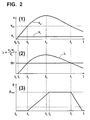
- FIG. 2 as an example, an anti-spin regulation which is executed by means of an hydraulic braking system (for example as described below while referring to FIG. 3) is illustrated.
- anti-spin regulation might be executed by any other braking system as well as additionally or alternatively by any engine control system without any effect on the invention itself.
- FIG.2 comprises three graphs (1), (2) and (3).
- quantities are depicted as functions of the time during the same time slot.
- the base axis of each graph (1), (2) and (3) is a time axis t and the time axes t of the three graphs (1), (2) and (3) are equal one to another.
- the remaining axis is a velocity axis v and the velocity of a vehicle v v as well as the velocity of a slipping wheel v w are depicted.
- the remaining axis is a pressure axis p and the pressure p of a pressurized medium within the hydraulic braking system is depicted.
- the vehicle is accelerated and hence the velocity of the vehicle v v is increased between a starting time t 0 and a first time t 1 (thereby, the velocity of the vehicle may be measured by means of any suitable method, for example by known means such as measuring the velocity of the non-driven wheels only, averaging velocities of several wheels etc.). Then, for simplicity, the velocity of the vehicle v v remains constant until a seventh time t 7 . However, any changes of the velocity of the vehicle v might occur during this period of time t 1 -t 7 without any effect on the invention.
- the slip ⁇ is the relative difference of the velocity of the slipping wheel v w and the velocity of the vehicle v v .
- any other suitable description of the slip ⁇ may be used with the invention (for example, the absolute instead of the relative velocity difference ⁇ v w,v may be used).
- the slip ⁇ of the slipping wheel exceeds a predefined slip threshold thr , as shown in graph (2).
- the slip threshold thr is assumed to be constant.
- the predefined slip threshold thr might be defined as any suitable function over the time without any effect on the invention.
- the slip threshold thr might depend on the velocity of the vehicle v v and therefore change over the time.
- an anti-slip regulation procedure is started.
- a corresponding delay might be desired in case an anti-spin regulation procedure should only be executed in case the slip threshold thr is exceeded for at least a minimum amount of time.
- pressure p is built up in an hydraulic braking system and therefore braking force is applied to the slipping wheel. Resulting therefrom, firstly, the acceleration of the slipping wheel is reduced between the second time t 2 and a third time t 3 . Then, at the third time t 3 , the acceleration of the slipping wheel is stopped. In the following time, a deceleration takes place and hence the velocity of the slipping wheel v w is reduced.
- a maximum pressure p max is achieved.
- said maximum pressure p max is held constant during a following period of time.
- any other suitable function of the pressure p over this period of time may be used.
- the termination of the anti-spin regulation is executed by control means (as described below while referring to FIG.3) and therefore the pressure p within the hydraulic brake system is reduced to zero during the following time.
- control means as described below while referring to FIG.3
- the termination might only be executed in case the velocity of the slipping wheel v w remains below the threshold velocity v thr for a minimum amount of time.
- FIG.1 an example is shown, how the anti-spin regulation described above is modified as according to the invention.
- the first, second and third graphs (1), (2) and (3) are replaced with corresponding modified graphs (1'), (2') and (3').
- a fourth graph (4) is depicted, which has the same time base as the remaining graphs (1'), (2') and (3'), but has an engine speed resp. average-speed-of-driven-wheels axis N resp. ⁇ V dr > as second axis and shows the engine speed N as well as the average speed of the driven wheels ⁇ v dr > as functions of the time.
- the first condition for this may be (but does not have to be), that the pressure p exceeds a certain minimum value p min as indicated by a dashed line in graph (3').
- the minimum pressure p min may be equal to or smaller as the maximum pressure p max .
- the pressure p itself may be measured by measuring means or estimated from the pressure building time (i.e. the time during which a pressure pump within the hydraulic system runs).
- a minimum pressure p min as a modification condition is useful in case of minor wheel slips which are compensated by slight braking procedures.
- a minimum pressure P min of 15 bar and, in case of an exemplary rear wheel drive, a minimum pressure p min of 40 bar can be used in order to avoid unnecessary modifications.
- the velocity of the slipping wheel v w has also reached its maximum at the third time t 3 (however, this just coincides with the maximum of the velocity of the slipping wheel v w , since the velocity of the vehicle v v is assumed to be constant during the time slot t 1- t 7 and since there is only one slipping wheel; hence, the velocity of a slipping wheel v w might reach its maximum before or after the engine speed N and/or the average speed of the driven wheels ⁇ v dr > reach their corresponding maxima). From this it is concluded, that the aim of the anti-spin regulation can be reasonably achieved, when the remaining part of the anti-spin regulation is modified as according to the invention. Hence, the further modification condition requires, that one or more of the aforementioned maxima are reached or passed over.
- the engine speed N and/or the individual wheel speeds are measured by measuring means (as described below while referring to FIG.3) at least after the minimum pressure p min is exceeded.
- the time derivations of the engine speed N, the average speed of the driven wheels ⁇ v dr > and/or the velocity of the slipping wheel v w are repeatedly calculated. In order to do so, the corresponding values are repeatedly measured and the foregoing value is subtracted from each current value.
- d N d t ⁇ ⁇ N ( n , n ⁇ 1 ) ⁇ t ( n , n ⁇ 1 ) ⁇ N ( t n ) ⁇ N ( t n ⁇ 1 ) ⁇ ⁇ t ( n , n ⁇ 1 ) which best holds for: ⁇ t ( n , n ⁇ 1 ) ⁇ 0
- the time interval should not be above 300-400 ms in order to reduce negative effects due to measuring disturbances.
- the modification itself in this example is done by means of adding an offset ⁇ thr to the slip threshold thr .
- the slip threshold thr is increased and the duration of the anti-spin regulation is decreased, since the termination thereof is executed as soon as (or sooner or later as) the slip ⁇ is below the modified slip threshold thr .
- the calculation of the offset ⁇ thr depends on whether the engine speed N or the average speed of the driven wheels ⁇ v dr > or the velocity of the slipping wheel v w are used for the control of the modification.
- the factors F N , F ⁇ vdr> or F vw may be constant or depend on further parameters such as different brake system modes etc.
- the offsets start with small values close to zero and are increased in accordance with the aforementioned time derivations.
- the offset ⁇ thr is limited by a predefined maximum value.
- the invention is particularly advantageous in case of an anti-slip regulation with a large share of braking regulation and a minor (or no) share of engine regulation. However, the invention does also improve a corresponding engine regulation system.
- FIG. 3 shows a hydraulic system which is eligible for use with the inventive method and implemented as a first brake circuit 10 of a hydraulic braking system within a car.
- the first brake circuit 10 is used for braking the right rear wheel 20 and the left rear wheel 30 of a car which has a rear wheel drive (hence, there is a second brake circuit for the remaining two wheels required which, for simplicity, is not shown in FIG. 3).
- a corresponding hydraulic brake system is referred to as "TT-brake circuit partition".
- any other hydraulic brake system (as well as any other wheel drive such as an all-wheel drive or a front wheel drive and any other hydraulic system in general) may be used with the inventive method.
- the inventive method also may be used within a "X-brake circuit partition" in a car which has a rear or a front wheel drive.
- the first brake circuit 10 has two independent pressure sources. Firstly, the car driver can produce pressure by pushing a brake pedal 40 which is connected to a main brake cylinder 50 with a pressurized medium reservoir 60. Secondly, there is a high pressure pump 70, which is driven by an electrical driving motor 80 and which is controlled by a control unit 90. Hence, the first brake circuit 10 is eligible for a simple pedal driven braking procedure as well as for use as a anti-lock braking system (ABS) or as an anti-spin regulation (ASR) system both of which require the implementation of the motor driven pressure pump 70 in order to build up pressures independently of what any car driver is doing.
- ABS anti-lock braking system
- ASR anti-spin regulation
- anti-lock braking is performed in principle by means of detecting wheel speeds during a braking procedure and frequently opening and closing individual wheel brakes 220, 230 in case a wheel speed is reduced to zero but the total speed of the car is not.
- anti-spin regulation is performed in principle by means of detecting wheel speeds during a starting or driving procedure and frequently closing and opening individual wheel brakes 220, 230 in case the speed of a driven wheel exceeds the speed of other wheels and/or the total speed of the car.
- wheel speed sensors 25, 35 are implemented, which are eligible to detect the speed of each individual wheel 20, 30.
- the wheel speed sensors 25 or 35 are used to monitor wheel speeds in general and in particular during an anti-spin regulation.
- the monitoring results are provided to the control unit 90.
- the average speed of the driven wheels ⁇ V dr > is determined.
- the engine speed N is detected by means of an engine speed sensor 280.
- the corresponding measuring results are provided to the control unit 90.
- the pressure within the hydraulic system is either detected by pressure sensors (not shown) or estimated by the control unit 90 from the pressure building time (i.e. the time during which a pressure is built up in a predefined way).
- the control unit is eligible to control the hydraulic braking system as according to the invention due to a corresponding soft- and/or hardware implementation.
- the first brake circuit 10 is brancned end comprises within its branches six 2/2 port directional control valves 100, 110, 120, 130, 140 and 150 (shortly: 2/2 valves 100, 110, 120, 130, 140 and 150).
- Each of these 2/2 valves 100, 110, 120, 130, 140, 150 can be switched between a bidirectional or one-directional in case of 2/2 valves 130 and 140) flow-through position FTP and a locking position LP.
- each switch is implemented by means of a spring-actuated first position (i.e. either the flow-through position FTP or the locking position LP) and an electromagnetically-actuated second position (i.e. either the locking position LP or the flow-through position FTP), as indicated in FIG. 3.
- each switch (and therefore each 2/2 valve 100, 110, 120, 130, 140, 150) is controlled by means of charging or discharging a corresponding electromagnetic magnet and said charging or discharging procedures are controlled by the contrcl unit 90.
- the first brake circuit 10 can be modified by the control unit 90 by means of opening and closing any of the 2/2 valves 100, 110, 120, 130, 140 and/or 150 and therefore opening and closing the individual branches of the first brake circuit 10.
- the first brake circuit can be set into several configurations which are required to perform simple pedal driven braking, ABS braking and/or ASR procedures.
- the first brake circuit is shown in a configuration eligible for simple pedal driven braking.
- pushing the pedal 40 results in a pressure production within the main brake cylinder 50.
- the pressure is transported within a pressurized medium along a root line 160, a first branch 170 (through the first 2/2 valve 100, in the following referred to as shut-off valve 100, which is in its flow-through position FTP) and a third and a fourth branch 190, 200 (through the second respectively third 2/2 valves 110 resp. 120, in the following referred to as first resp. second inlet 2/2 valves 110, 120, which are in their flow-through positions FTP). From this, a first and a second wheel brake 220, 230 are activated.
- any anti-spin regulation can be performed by the system as according to the state of the art. While doing so, the wheel speed sensors 25 or 35 can be used to monitor each non-braked wheel.
- the control unit 90 can be used to determine whether the non-braked wheel tends 20 or 30 to slip or not while using the monitoring results. Then, whenever a slipping trend occurs, the control unit 90 can cause the system to brake the non-braked wheel 20 or 30 as described above.
- any other eligible braking system can be used with the invention.
- the control unit 90 may be used in order to determine whether the non-braked wheel tends 20 or 30 to slip or not while using the monitoring results.
- additional wheel speed sensors may be used in order to detect slipping trends (for example, the additional wheel speed sensors might be more sensitive than the ordinary available wheel speed sensors 25 and 35).
Claims (11)
- Verfahren für eine Antischlupfregelung (ASR) für ein Fahrzeug, wobei a) eine Antischlupfregelung durch Regelungsmittel (90, 10) ausgeführt wird, wenn ein Schwellenwert (thr) für den Schlupf (λ) eines Rades (20, 30) überschritten wird, und b) der Schwellenwert (thr) durch Modifikationsmittel (90) modifiziert wird, während der Antischlupfregelungsvorgang ausgeführt wird, dadurch gekennzeichnet, dass c) die Motordrehzahl (N), die Geschwindigkeit (vw) des durchdrehenden Rades und/oder die Durchschnittsgeschwindigkeit der angetriebenen Räder (<vdr>, 20, 30) durch Bestimmungsmittel (25, 35, 90, 280) bestimmt werden und d) die Modifikation des Schwellenwertes (thr) während des Antischlupfregelungsvorgangs durch die Modifikationsmittel (90) ausgeführt wird, wenn die Motordrehzahl (N), die Geschwindigkeit (vw) des durchdrehenden Rades und/oder die Durchschnittsgeschwindigkeit (<vdr>) der angetriebenen Räder abnehmen.
- Verfahren nach Anspruch 1, dadurch gekennzeichnet, dass a) die Antischlupfregelung wenigstens teilweise mittels eines Bremssystems (10) durchgeführt wird; b) ein Bremsvorgang durch Regelungsmittel (90) begonnen wird, wenn der Schwellenwert (thr) für den Schlupf (λ) des Rades (20, 30) überschritten wird; und c) die Beendigung des Bremsvorgangs durch die Regelungsmittel (90) ausgeführt wird, wenn der Schlupf (λ) des Rades (20, 30) unterhalb des Schwellenwertes (thr) liegt.
- Verfahren nach einem der vorhergehenden Ansprüche, dadurch gekennzeichnet, dass a) das Bremssystem (10) ein hydraulisches Bremssystem ist; b) der Druck (p) innerhalb des hydraulischen Systems (10) durch Bestimmungsmittel (90) bestimmt wird; und c) die Modifikation des Schwellenwertes (thr) während des Antischlupfvorgangs durch die Modifikationsmittel (90) ausgeführt wird, wenn der Druck (p) einen vorher festgelegten Minimaldruck (pmin) überschreitet.
- Verfahren nach einem der vorhergehenden Ansprüche, dadurch gekennzeichnet, dass a) die Motordrehzahl (N), die Geschwindigkeit (vw) des durchdrehenden Rades und/oder die Durchschnittsgeschwindigkeit der angetriebenen Räder, (<vdr>, 20, 30) fortlaufend und/oder wiederholt durch Bestimmungsmittel (25, 35, 90, 280) bestimmt werden; b) die bestimmte Motordrehzahl (N), die Geschwindigkeit (vw) des durchdrehenden Rades und/oder die Durchschnittsgeschwindigkeit (<vdr>) der angetriebenen Räder über die Zeit differenziert werden; und c) die Modifikation des Schwellenwertes (thr) während des Antischlupfvorgangs durch die Modifikationsmittel (90) ausgeführt wird, wenn die Zeitableitung der Motordrehzahl (N), die Zeitableitung der Geschwindigkeit (vw) des durchdrehenden Rades und/oder die Zeitableitung der Durchschnittsgeschwindigkeit (<vdr>) der angetriebenen Räder negativ sind.
- Verfahren nach einem der vorhergehenden Ansprüche, dadurch gekennzeichnet, dass der Schwellenwert (thr) während des Antischlupfregelungsvorgangs vergrößert wird.
- Verfahren nach einem der vorhergehenden Ansprüche, dadurch gekennzeichnet, dass zu dem Schwellenwert (thr) während des Antischlupfregelungsvorgangs ein Ausgleich (Δthr) addiert wird.
- Verfahren nach Anspruch 6, dadurch gekennzeichnet, dass der Ausgleich (Δthr) mittels a) Umkehrung des negativen Wertes der Zeitableitung der Geschwindigkeit des durchdrehenden Rades (vw, 20, 30); und b) Multiplikation des erhaltenen Ergebnisses mit einem vorher festgelegten Faktor (Fvw) berechnet wird.
- Verfahren nach einem der Ansprüche 6 bis 7, dadurch gekennzeichnet, dass der Ausgleich (Δthr) mittels a) Umkehrung des negativen Wertes der Zeitableitung der Motordrehzahl (N); und b) Multiplikation des erhaltenen Ergebnisses mit einem vorher festgelegten Faktor (FN) berechnet wird.
- Verfahren nach einem der Ansprüche 6 bis 8, dadurch gekennzeichnet, dass der Ausgleich (Δthr) mittels a) Umkehrung des negativen Wertes der Zeitableitung der Durchschnittsgeschwindigkeit (<vdr>) der angetriebenen Räder; und b) Multiplikation des erhaltenen Ergebnisses mit einem vorher festgelegten Faktor (F<vdr>) berechnet wird.
- Verfahren nach einem der Ansprüche 6 bis 9, dadurch gekennzeichnet, dass der Ausgleich (Δthr) durch einen vorher festgelegten Maximal- und/oder einen vorher festgelegten Minimalwert (thrmax) begrenzt wird.
- Vorrichtung für eine Antischlupfregelung (ASR) für ein Fahrzeug, insbesondere geeignet zur Verwendung mit einem Verfahren nach einem der vorhergehenden Ansprüche, wobei a) eine Antischlupfregelung durch Regelungsmittel (90, 10) ausgeführt werden kann, wenn ein Schwellenwert (thr) für den Schlupf (λ) eines Rades (20, 30) überschritten wird, und b) der Schwellenwert (thr) durch Modifikationsmittel (90) während des Antischlupfregelungsvorgangs verändert werden kann, dadurch gekennzeichnet, dass die Vorrichtung konfiguriert ist, um c) die Motordrehzahl (N), die Geschwindigkeit (vw) des durchdrehenden Rades und/oder die Durchschnittsgeschwindigkeit der angetriebenen Räder (<vdr>, 20, 30) durch Bestimmungsmittel (25, 35, 90, 280) zu bestimmen und d) die Modifikation des Schwellenwertes (thr) während des Antischlupfregelungsvorgangs durch die Modifikationsmittel (90) auszuführen, wenn die Motordrehzahl (N), die Geschwindigkeit (vw) des durchdrehenden Rades und/oder die Durchschnittsgeschwindigkeit (<vdr>) der angetriebenen Räder abnehmen.
Priority Applications (3)
| Application Number | Priority Date | Filing Date | Title |
|---|---|---|---|
| DE69933685T DE69933685T2 (de) | 1999-12-30 | 1999-12-30 | Verfahren und Vorrichtung zur Kraftfahrzeug -Antischlupfregelung |
| EP19990126205 EP1112903B1 (de) | 1999-12-30 | 1999-12-30 | Verfahren und Vorrichtung zur Kraftfahrzeug -Antischlupfregelung |
| JP2000396440A JP2001213298A (ja) | 1999-12-30 | 2000-12-27 | 車輛用スピン防止規制(asr)用の方法及び装置 |
Applications Claiming Priority (1)
| Application Number | Priority Date | Filing Date | Title |
|---|---|---|---|
| EP19990126205 EP1112903B1 (de) | 1999-12-30 | 1999-12-30 | Verfahren und Vorrichtung zur Kraftfahrzeug -Antischlupfregelung |
Publications (2)
| Publication Number | Publication Date |
|---|---|
| EP1112903A1 EP1112903A1 (de) | 2001-07-04 |
| EP1112903B1 true EP1112903B1 (de) | 2006-10-18 |
Family
ID=8239773
Family Applications (1)
| Application Number | Title | Priority Date | Filing Date |
|---|---|---|---|
| EP19990126205 Expired - Lifetime EP1112903B1 (de) | 1999-12-30 | 1999-12-30 | Verfahren und Vorrichtung zur Kraftfahrzeug -Antischlupfregelung |
Country Status (3)
| Country | Link |
|---|---|
| EP (1) | EP1112903B1 (de) |
| JP (1) | JP2001213298A (de) |
| DE (1) | DE69933685T2 (de) |
Family Cites Families (6)
| Publication number | Priority date | Publication date | Assignee | Title |
|---|---|---|---|---|
| DE3419716A1 (de) | 1984-05-26 | 1985-11-28 | Robert Bosch Gmbh, 7000 Stuttgart | Antriebsschlupfregelsystem |
| DE3728574C1 (de) * | 1987-08-27 | 1988-11-24 | Daimler Benz Ag | Einrichtung zum Regeln des Antriebsmomentes eines Kraftfahrzeuges |
| DE3806213A1 (de) * | 1988-02-26 | 1989-09-07 | Lucas Ind Plc | Verfahren zum regeln des bremsdruckes |
| DE4031707C2 (de) * | 1990-10-06 | 2000-08-03 | Continental Teves Ag & Co Ohg | Schaltungsanordnung für eine Bremsanlage mit Blockierschutz- oder Antriebsschlupfregelung |
| DE4301676A1 (de) * | 1993-01-22 | 1994-07-28 | Teves Gmbh Alfred | Antriebsschlupfregelungssystem mit Bremsen- und/oder Motoreingriff |
| DE19538545A1 (de) * | 1995-10-17 | 1997-04-24 | Teves Gmbh Alfred | Verfahren zur Verbesserung des Regelverhaltens einer Bremsanlage |
-
1999
- 1999-12-30 EP EP19990126205 patent/EP1112903B1/de not_active Expired - Lifetime
- 1999-12-30 DE DE69933685T patent/DE69933685T2/de not_active Expired - Lifetime
-
2000
- 2000-12-27 JP JP2000396440A patent/JP2001213298A/ja not_active Withdrawn
Also Published As
| Publication number | Publication date |
|---|---|
| DE69933685D1 (de) | 2006-11-30 |
| JP2001213298A (ja) | 2001-08-07 |
| EP1112903A1 (de) | 2001-07-04 |
| DE69933685T2 (de) | 2007-08-23 |
Similar Documents
| Publication | Publication Date | Title |
|---|---|---|
| US7699411B2 (en) | Antiskid control apparatus for vehicle | |
| JP3248414B2 (ja) | 車輌の挙動制御装置 | |
| JP4148302B2 (ja) | アンチロツクシステムを有する車両におけるヨーイングモーメントを減衰する方法 | |
| JP3258476B2 (ja) | 車両走行路面の最大摩擦係数推定装置 | |
| KR960007037B1 (ko) | 차량의 앤티스키드브레이크장치 | |
| US7448700B2 (en) | Anti-lock brake control device and brake control device | |
| EP0259884B1 (de) | Vorrichtung zur Regelung des Radschlupfs | |
| US5551769A (en) | Method and system for split mu control for anti-lock brake systems | |
| EP1504974B1 (de) | Hydraulische Fahrzeugbremssteuereinheit | |
| CA1252181A (en) | Antiskid control system responsive to road surface reaction | |
| JPH0986377A (ja) | 液圧制御装置 | |
| JP4543484B2 (ja) | ブレーキ液圧制御装置 | |
| EP1112904B1 (de) | Verfahren und Vorrichtung zur Antriebschlupfregelung (ASR) eines Kraftfahrzeugs | |
| EP1112903B1 (de) | Verfahren und Vorrichtung zur Kraftfahrzeug -Antischlupfregelung | |
| JP3508210B2 (ja) | アンチスキッド制御装置 | |
| JPH054574A (ja) | アンチスキツド制御装置 | |
| JP3572647B2 (ja) | 路面摩擦係数推定装置 | |
| KR0121742B1 (ko) | 안티록 브레이크 시스템의 동작제어방법 | |
| JPH058713A (ja) | 車両のスリツプ制御装置 | |
| JP3541061B2 (ja) | ブレーキ液圧制御方法およびその装置 | |
| JP3696259B2 (ja) | 制動力制御装置 | |
| KR100353247B1 (ko) | 안티록 브레이크 제어방법 | |
| JPH0725328A (ja) | 車両のアンチスキッドブレ−キ装置 | |
| JPH0858554A (ja) | アンチスキッド制御装置 | |
| JPH08324405A (ja) | アンチスキッド制御装置 |
Legal Events
| Date | Code | Title | Description |
|---|---|---|---|
| PUAI | Public reference made under article 153(3) epc to a published international application that has entered the european phase |
Free format text: ORIGINAL CODE: 0009012 |
|
| AK | Designated contracting states |
Kind code of ref document: A1 Designated state(s): AT BE CH CY DE DK ES FI FR GB GR IE IT LI LU MC NL PT SE |
|
| AX | Request for extension of the european patent |
Free format text: AL;LT;LV;MK;RO;SI |
|
| 17P | Request for examination filed |
Effective date: 20010806 |
|
| AKX | Designation fees paid |
Free format text: AT BE CH CY DE DK ES FI FR GB GR IE IT LI LU MC NL PT SE |
|
| GRAP | Despatch of communication of intention to grant a patent |
Free format text: ORIGINAL CODE: EPIDOSNIGR1 |
|
| GRAS | Grant fee paid |
Free format text: ORIGINAL CODE: EPIDOSNIGR3 |
|
| GRAA | (expected) grant |
Free format text: ORIGINAL CODE: 0009210 |
|
| AK | Designated contracting states |
Kind code of ref document: B1 Designated state(s): DE GB |
|
| REG | Reference to a national code |
Ref country code: GB Ref legal event code: FG4D |
|
| REF | Corresponds to: |
Ref document number: 69933685 Country of ref document: DE Date of ref document: 20061130 Kind code of ref document: P |
|
| PLBE | No opposition filed within time limit |
Free format text: ORIGINAL CODE: 0009261 |
|
| STAA | Information on the status of an ep patent application or granted ep patent |
Free format text: STATUS: NO OPPOSITION FILED WITHIN TIME LIMIT |
|
| 26N | No opposition filed |
Effective date: 20070719 |
|
| PGFP | Annual fee paid to national office [announced via postgrant information from national office to epo] |
Ref country code: GB Payment date: 20101221 Year of fee payment: 12 |
|
| PGFP | Annual fee paid to national office [announced via postgrant information from national office to epo] |
Ref country code: DE Payment date: 20120221 Year of fee payment: 13 |
|
| GBPC | Gb: european patent ceased through non-payment of renewal fee |
Effective date: 20111230 |
|
| PG25 | Lapsed in a contracting state [announced via postgrant information from national office to epo] |
Ref country code: GB Free format text: LAPSE BECAUSE OF NON-PAYMENT OF DUE FEES Effective date: 20111230 |
|
| REG | Reference to a national code |
Ref country code: DE Ref legal event code: R119 Ref document number: 69933685 Country of ref document: DE Effective date: 20130702 |
|
| PG25 | Lapsed in a contracting state [announced via postgrant information from national office to epo] |
Ref country code: DE Free format text: LAPSE BECAUSE OF NON-PAYMENT OF DUE FEES Effective date: 20130702 |