EP1112902A2 - Adaptive Aufblasvorrichtung - Google Patents
Adaptive Aufblasvorrichtung Download PDFInfo
- Publication number
- EP1112902A2 EP1112902A2 EP00204351A EP00204351A EP1112902A2 EP 1112902 A2 EP1112902 A2 EP 1112902A2 EP 00204351 A EP00204351 A EP 00204351A EP 00204351 A EP00204351 A EP 00204351A EP 1112902 A2 EP1112902 A2 EP 1112902A2
- Authority
- EP
- European Patent Office
- Prior art keywords
- air bag
- cushion
- inflator
- bag cushion
- slide
- Prior art date
- Legal status (The legal status is an assumption and is not a legal conclusion. Google has not performed a legal analysis and makes no representation as to the accuracy of the status listed.)
- Withdrawn
Links
Images


Classifications
-
- B—PERFORMING OPERATIONS; TRANSPORTING
- B60—VEHICLES IN GENERAL
- B60R—VEHICLES, VEHICLE FITTINGS, OR VEHICLE PARTS, NOT OTHERWISE PROVIDED FOR
- B60R21/00—Arrangements or fittings on vehicles for protecting or preventing injuries to occupants or pedestrians in case of accidents or other traffic risks
- B60R21/02—Occupant safety arrangements or fittings, e.g. crash pads
- B60R21/16—Inflatable occupant restraints or confinements designed to inflate upon impact or impending impact, e.g. air bags
- B60R21/26—Inflatable occupant restraints or confinements designed to inflate upon impact or impending impact, e.g. air bags characterised by the inflation fluid source or means to control inflation fluid flow
- B60R21/276—Inflatable occupant restraints or confinements designed to inflate upon impact or impending impact, e.g. air bags characterised by the inflation fluid source or means to control inflation fluid flow with means to vent the inflation fluid source, e.g. in case of overpressure
-
- B—PERFORMING OPERATIONS; TRANSPORTING
- B60—VEHICLES IN GENERAL
- B60R—VEHICLES, VEHICLE FITTINGS, OR VEHICLE PARTS, NOT OTHERWISE PROVIDED FOR
- B60R21/00—Arrangements or fittings on vehicles for protecting or preventing injuries to occupants or pedestrians in case of accidents or other traffic risks
- B60R21/02—Occupant safety arrangements or fittings, e.g. crash pads
- B60R21/16—Inflatable occupant restraints or confinements designed to inflate upon impact or impending impact, e.g. air bags
- B60R21/23—Inflatable members
- B60R21/231—Inflatable members characterised by their shape, construction or spatial configuration
- B60R21/2334—Expansion control features
- B60R21/2338—Tethers
- B60R2021/23382—Internal tether means
-
- B—PERFORMING OPERATIONS; TRANSPORTING
- B60—VEHICLES IN GENERAL
- B60R—VEHICLES, VEHICLE FITTINGS, OR VEHICLE PARTS, NOT OTHERWISE PROVIDED FOR
- B60R21/00—Arrangements or fittings on vehicles for protecting or preventing injuries to occupants or pedestrians in case of accidents or other traffic risks
- B60R21/02—Occupant safety arrangements or fittings, e.g. crash pads
- B60R21/16—Inflatable occupant restraints or confinements designed to inflate upon impact or impending impact, e.g. air bags
- B60R21/26—Inflatable occupant restraints or confinements designed to inflate upon impact or impending impact, e.g. air bags characterised by the inflation fluid source or means to control inflation fluid flow
- B60R21/276—Inflatable occupant restraints or confinements designed to inflate upon impact or impending impact, e.g. air bags characterised by the inflation fluid source or means to control inflation fluid flow with means to vent the inflation fluid source, e.g. in case of overpressure
- B60R2021/2765—Inflatable occupant restraints or confinements designed to inflate upon impact or impending impact, e.g. air bags characterised by the inflation fluid source or means to control inflation fluid flow with means to vent the inflation fluid source, e.g. in case of overpressure comprising means to control the venting
-
- B—PERFORMING OPERATIONS; TRANSPORTING
- B60—VEHICLES IN GENERAL
- B60R—VEHICLES, VEHICLE FITTINGS, OR VEHICLE PARTS, NOT OTHERWISE PROVIDED FOR
- B60R21/00—Arrangements or fittings on vehicles for protecting or preventing injuries to occupants or pedestrians in case of accidents or other traffic risks
- B60R21/02—Occupant safety arrangements or fittings, e.g. crash pads
- B60R21/16—Inflatable occupant restraints or confinements designed to inflate upon impact or impending impact, e.g. air bags
- B60R21/20—Arrangements for storing inflatable members in their non-use or deflated condition; Arrangement or mounting of air bag modules or components
- B60R21/217—Inflation fluid source retainers, e.g. reaction canisters; Connection of bags, covers, diffusers or inflation fluid sources therewith or together
- B60R21/2171—Inflation fluid source retainers, e.g. reaction canisters; Connection of bags, covers, diffusers or inflation fluid sources therewith or together specially adapted for elongated cylindrical or bottle-like inflators with a symmetry axis perpendicular to the main direction of bag deployment, e.g. extruded reaction canisters
Definitions
- the present invention relates generally to vehicle supplemental inflatable restraint systems and, more particularly, to an air bag module that provides variable output inflation of an air bag cushion from a single inflator.
- SIR systems typically include an air bag stored in a housing module within the interior of the vehicle in close proximity to either the driver or one or more passengers. SIR systems are designed to actuate upon sudden deceleration so as to rapidly deploy an air bag to restrain the movement of the driver or passengers. During deployment, gas is emitted rapidly from an inflator into the air bag to expand it to a fully inflated state.
- Air bag passive restraint systems include an inflator, which produces gas to inflate the air bag cushion.
- Known inflators for air bag modules are generally of three types.
- One type is the pure gas inflator wherein a pressure vessel contains stored pressurized gas. The pressure vessel communicates with the cushion through various types of rupturable outlets or diaphragms.
- Another type is the gas generator wherein a propellant is ignited and the resultant gas created flows through an outlet to the cushion.
- a third type is the hybrid or augmented type. This type includes a pressure vessel containing stored pressurized gas and a gas generator. When the generator is ignited, the resultant gas flows with and heats the stored gas going to the cushion through the pressure vessel outlet.
- Devices which provide primary inflation (reduced inflation) and full level inflation using a single gas vessel with two separate gas heaters. Primary inflation is accomplished by actuating the gas vessel and heating the gas at a specified reduced level. Full level inflation is accomplished by actuating a second separate heater located at the bottom of the gas vessel to heat the gas at a greater level. This second heater is deployed at the same time or a delayed time as the primary heater to provide full level inflation. It is also known in the art to use a system having two discrete inflators to accomplish dual level inflation. In these types of systems, two discrete inflators are deployed at the same time or at a delayed time depending upon the severity of the sudden deceleration.
- the air bag module includes an inflator, a cushion retainer, a slide mechanism, and a base plate for supporting the inflator, the slide mechanism, and the cushion retainer.
- the cushion retainer includes inner and outer annular walls, wherein the slide mechanism is disposed between the inner and outer annular walls.
- the cushion retainer includes at least one and preferably a plurality of diffuser openings and the slide mechanism comprises a rotatable ring having openings formed in an annular wall thereof.
- the slide mechanism has connecting tabs at an upper edge thereof and each connecting tab is connected to a first end of a tether. The second end of the tether is secured to a rear surface of an air bag cushion.
- the air bag cushion is disposed about the inflator, cushion retainer and base plate, wherein the air bag cushion is retained to the cushion retainer.
- a controller actuates the inflator to cause generation of heated inflator gas.
- the heated inflator gas is discharged through vent ports formed in the inflator and flows initially according to a first fluid flow path in which the heated inflator gas flows into the air bag cushion.
- the air bag cushion begins to inflate the rear surface thereof becomes under stress and the second end of each tether attached to the air bag cushion tightens. Because the first end of the tether is attached to the connecting tab of the slide ring, the slide ring is rotated about the cushion retainer as a result of the tightening of the tether. As the slide ring rotates, the openings formed within the slide ring axially align with the openings formed in the cushion retainer.
- the alignment of the openings effectively opens a second fluid flow path, wherein the heated inflator gas flows through the openings of the cushion retainer and the slide ring and exits the air bag module through an opening formed in the base plate.
- the heated inflator gas flows through the openings of the cushion retainer and the slide ring and exits the air bag module through an opening formed in the base plate.
- the use of the slide mechanism and attached tethers provides a direct mechanical system for cushion pressure feedback to tailor the inflation. More specifically, the use of tethers in combination with the slide ring permits the pressure of the air bag cushion to be sensed, due to the unfolding action of the air bag cushion, and when the cushion pressure reaches a predetermined level, some of the heated inflator gas is vented off and is directed out the air bag module away from the air bag cushion.
- the slide mechanism of the present invention permits the proper variable inflation of the air bag cushion when the occupant is in either a forward position in a seat, a more rearward position in the seat, or positions therebetween.
- the inflating air bag cushion contacts the occupant earlier in the inflation process than if the occupant was seated more rearwardly in the seat.
- the rear surface of the air bag cushion will become stressed earlier in time than if the occupant was seated more rearwardly. Accordingly, the tether is tightened earlier resulting in the rotation of the slide ring to thereby open the second fluid flow path.
- the slide mechanism provides variable inflation and the slide mechanism is designed to actuate depending upon the positioning of the occupant so as to inflate the air bag cushion to a desired predetermined level.
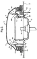
- an air bag module according to a first embodiment is generally designated at 10.
- the air bag module 10 is suitably mounted to a central hub of a steering wheel (not shown).
- the air bag module 10 includes an inflator 12 for generating inflator gas upon the sensing of predetermined vehicle conditions, i.e. rapid deceleration, to inflate an air bag cushion 14.
- Inflator 12 has a predetermined number of vent ports 16 radially disposed within inflator 12.
- a cushion retainer 18 is disposed about the inflator for directing gases from the inflator 12 to the air bag cushion 14.
- the cushion retainer 18 comprises an annular member and further includes a predetermined number of diffuser openings 20 which fluidly communicate with the air bag cushion 14 and permit inflator gas to pass into and inflate the air bag cushion 14 under deployment conditions.
- the inflator 12 shown is commonly used for an air bag module 10 installed in a driver side of a vehicle to protect the driver thereof.
- a second embodiment of an air bag module 200 according to the present invention for use with other passive restraints, i.e., passenger side air bag modules and side impact air bag modules will be described hereinafter with reference to Figures 5-6.
- a controller (not shown), e.g., a sensing and actuating system, generates an ignition signal to the inflator 12 in response to velocity responsive sensors (not shown) mounted on the vehicle bumper and/or acceleration, or inertia responsive sensors mounted on a part of the vehicle occupant compartment, such as the fire wall.
- the controller provides an ignition signal to the inflator 12 to initiate deployment inflation of the air bag cushion 14 in accordance with a predetermined level of deceleration.
- the inflator 12 releases an appropriate predetermined volume of gas into the air bag cushion 14 through the vent ports 16 of the inflator 12.
- the level of deployment of the air bag cushion 14 is partially dependent upon on the actuation of a slide actuator assembly 30 slidably arranged to selectively restrict or prevent gas flow away from the air bag cushion 14, as will be described hereinafter.
- Inflator 12 may be of any conventional construction for generating inflator gas to inflate the air bag cushion 14.
- the inflator 12 is preferably a single stage inflator which outputs inflator gas to inflate the air bag cushion 14.
- the inflator 12 has a generally cylindrical body portion and a flange 34 that suitably secures to a base plate 41.
- the vent ports 16 are preferably formed in a side wall 42 of inflator 12 and extend around side wall 42 of inflator 12 in a radial manner and it is understood that the number and dimension of the vent ports 16 may be varied according to the precise application and configuration of the inflator 12.
- An initiator or pyrotechnic device (not shown) disposed within the inflator 12 ignites pyrotechnic material which generates heated gas that discharges through the discharge vent ports 16 to inflate the air bag cushion 14.
- the base plate 41 supports both the inflator 12, a slide mechanism 30, and a cushion retainer 18.
- the inflator 12 is mounted within a central opening 46 of the base plate 41 by known techniques, including the use of a plurality of threaded studs (not shown) extending from a bottom surface thereof.
- the base plate 41 includes first slots 52 disposed about the central opening 46 which provides a gas venting path for directing inflator gas away from the air bag cushion 14.
- First slots 52 comprise a vent opening for venting the inflator gas away from the air bag cushion 14 under predetermined conditions.
- the slide mechanism 30 comprising a slide ring member having an annular wall 70 which defines a central opening 72.
- the annular wall 70 has an upper edge 74 and an opposing lower edge 76.
- Extending upwardly from the upper edge 74 is a pair of connecting tabs 78.
- the connecting tabs 78 are integral with the annular wall 70 and each connecting tab 78 includes an opening 81 formed therein.
- the connecting tabs 78 are spaced about the upper edge 74 so that one connecting tab 78 generally opposes the other connecting tab 78. In other words, connecting tabs 78 are orientated about 180° from each other.
- Slide ring 30 further includes a plurality of vent ports 80 formed in annular wall 70.
- the exemplary vent ports 80 are generally rectangular shaped openings formed in the annular wall 70.
- the vent ports 80 are off set from the connecting tabs 78.
- the vent ports 80 are formed in the annular wall 70 so that the vent ports 80 oppose one another.
- the vent ports 80 are also preferably orientated about 180° from each other.
- the cushion retainer 18 includes an annular inner wall 82 and an annular outer wall 84.
- Annular inner wall 82 includes diffuser openings 20 for venting the inflator gas away from the inflator 12 as will be described in greater detail hereinafter.
- Annular outer wall 84 includes an outer flange 88 which extends therefrom, wherein the outer flange 88 includes an upwardly extending lip 90 about its outer periphery.
- Cushion retainer 18 includes a generally horizontal wall 92 extending between the annular inner wall 82 and the annular outer wall 84. When assembled, the horizontal wall 92 of the cushion retainer 18 extends above the vent ports 16 of the inflator 12.
- the air bag cushion 14 is disposed between the outer flange 88 and the annular outer wall 84.
- slots 94 Formed in the cushion retainer 18, more specifically in the horizontal section 92, are slots 94 which receive the connecting tabs 78.
- the slots 94 comprise arcuate slots which permit movement of the connecting tabs 78 therein between end walls of the slots 94. Accordingly, the degree of movement of the connecting tabs 78 within the slots 94 depends on the length of the slots 94.
- the slide ring 30 is disposed between the annular inner wall 82 and the annular outer wall 84 and the connecting tabs 78 are disposed within the slots 94.
- the vent ports 80 of the slide ring 30 are not axially aligned with the diffuser openings 20 formed in the annular inner wall 82 of the cushion retainer 18 so that the inflator gas flows according to a first fluid flow path generally indicated at 100.
- the first fluid flow path 100 comprises a fluid flow path in which the inflator gas flows from the inflator 12 through the vent ports 16 and into the air bag cushion 14 for inflation thereof.
- the inflator gas is prevented from flowing away from the air bag cushion 14 through the first slots 52 because the vent ports 80 and the diffuser openings 20 are not aligned relative to each other.
- the inflator gas thus is directed by the cushion retainer 18, more specifically the annular inner wall 82, upward into the air bag cushion 14.
- the default or normal position of the air bag module 10 is the first closed position shown in Figure 1.
- the vent ports 80 of the slide ring 30 are axially aligned with the diffuser openings 20 formed in the annular inner wall 82 of the cushion retainer 18 so that the inflator gas flows according to a second fluid flow path generally indicated at 110 and according to the first fluid flow path generally indicated at 100.
- the second fluid flow path 110 some of inflator gas generated in the inflator 12 exits therefrom by flowing through the vent ports 16 through the aligned vent ports 80 and the diffuser openings 20 before flowing through the first slots 52 formed in the base plate 41. Accordingly, the volume of inflator gas which flows according to the second fluid flow path 110 exits the air bag module 10 and is directed away from the air bag cushion 14.
- the slide ring 30 is connected to a pair tethers 120 which themselves are connected to a portion of the air bag cushion 14.
- Each tether 120 has a first end 122 which is secured to one of connecting tabs 78.
- the first end 122 is secured to the connecting tab 78 by disposing the first end 122 through the opening 81 formed in the connecting tab 78.
- An opposing second end 124 of the tether 120 is secured to a portion of the air bag cushion 14.
- the air bag cushion 14 is folded to fit between the outer flange 88 and the annular outer wall 84 of the cushion retainer 18.
- the air bag cushion 14 includes a rear surface 15 which generally faces the annular outer wall 84 and the inflator 12 when the air bag cushion 14 is disposed thereabout.
- the second end 124 of the tether 120 is secured to the rear surface 15 of the air bag cushion 14.
- the controller actuates the inflator 12 to cause generation of heated inflator gas.
- the inflator 12 has a pyrotechnic initiator 19 which upon actuation ignites pyrotechnic material of the inflator 12 to generate the heated inflator gas.
- the heated inflator gas is discharged through the vent ports 16 of the inflator 12 and flows according to the first fluid flow path 100 into the air bag cushion 14. As the air bag cushion 14 begins to inflate, the air bag cushion 14 begins to unfold and is directed away from the cushion retainer 18.
- the inflation of the air bag cushion 14 causes the rear surface 15 of the air bag cushion 14 to become stressed (skin stress). As the rear surface 15 is stressed, the tether 120 is pulled tighter because the second end 124 thereof is attached to the rear surface 15, which is under stress. It will be appreciated that the present invention permits the pressure of the air bag cushion 14 to be sensed and when the pressure reaches a predetermined level, the tether 120 is tightened.
- the tightening of the tether 120 results in the slide ring 30 being rotationally twisted relative to the cushion retainer 40. More specifically, because first ends 122 are attached to the connecting tabs 78, the tightening of the slide ring 30 causes the slide ring 30 to be rotationally disposed about the cushion retainer 18 and the vent ports 80 of the slide ring 30 are axially aligned with the diffuser openings 20 of the cushion retainer 40. The alignment of the vent ports 80 and the diffuser openings 20 effectively opens the second fluid flow path 110 and permits some of the heated inflator gas to flow away from the air bag cushion 14 through the first slot 52 formed in the base plate 41.
- the predetermined level may be selected by varying parameters relating to the use of tether 120 as an actuator for causing the rotation of slide ring 30.
- the length of the tether 120 may be varied so that the tether 120 tightens at various air bag cushion pressures.
- the air bag module 10 provides variable output inflation of the air bag cushion 14 from a single inflator 12. This second open position is illustrated in Figure 2.
- the use of the slide ring 30 of the present invention permits the proper variable inflation of the air bag cushion 14 when the occupant is in either a forward position in a seat (not shown), a more rearward position in the seat, or positions therebetween.
- the inflating air bag cushion 14 contacts the occupant earlier in the inflation process than if the occupant than if the occupant was seated more rearwardly in the seat.
- the rear surface 15 of the air bag cushion 14 will become stressed earlier in time than if the occupant was seated more rearwardly.
- the tether 120 is tightened earlier resulting in the rotation of the slide ring 30 to thereby open the second fluid flow path 110.
- the actuation of the slide ring 30 occurs sooner in time than if the occupant is seated more rearwardly.
- the air bag cushion 14 inflates to a greater volume before contacting the occupant.
- the slide ring 30 is actuated to direct some of the inflator gas away from the air bag cushion 14.
- the slide ring 30 provides variable inflation and is designed to actuate depending upon the positioning of the occupant so as to inflate the air bag cushion 14 to a desired, predetermined level.
- FIGS 5-6 illustrate an air bag module according to a second embodiment of the present invention and is generally indicated at 200.
- Figure 5 illustrates the air bag module 200 in a closed position
- Figure 6 illustrates the air bag module 200 in an open position.
- Air bag module 200 is preferably intended for use in a passenger or side impact passive restraint systems.
- Air bag module 200 is similar to air bag module 100 with like elements being numbered alike.
- Air bag module 200 includes a module housing 202 having inflator 204 disposed therein.
- Inflator 204 includes a plurality of vent ports 16 formed therein.
- the air bag module housing 202 includes an opening 206 formed in a lower wall 208 thereof. The opening 206 acts as a vent port for directing heated inflator gas away from the air bag cushion 14.
- the module housing 202 further includes a slide mechanism 210 which is preferably coupled to the lower wall 208 of the air bag module housing 202.
- the slide mechanism 210 has an opening 212 formed therein.
- the exemplary illustrated slide mechanism 210 has a planar first surface 214 and a beveled section 216 formed between planar ends 217, 218 of the slide mechanism 210. More specifically, the beveled section 216 is formed of a beveled segment 220 formed adjacent the opening 212 and a vertical section 222 connecting one end of the beveled segment 220 to planar end 218.
- the vertical section 222 is substantially perpendicular to the planar end 218. Formed between the vertical section 222 and the planar end 218 is a first retaining opening 240.
- Module housing 202 includes an end wall 230.
- the end wall 230 includes a slot 232 formed therein so that planar end 218 of the slide mechanism 210 may be received therein during actuation of slide mechanism 210.
- the module housing 202 also has a second retaining opening 241 formed therein. Second retaining opening 241 is formed between opening 206 and the end wall 230.
- first and second retaining openings 240, 241 have a complementary shape and complementary dimensions.
- the slide mechanism 210 covers the opening 206 to prevent the heated inflator gas from flowing therethrough and away from the air bag cushion 14.
- the opening 206 are covered by the beveled segment 220 of the slide mechanism 210.
- the slide mechanism 210 is retained in the closed position by retaining member 250 which is received within the first retaining opening 240 and extends through to the second retaining opening 241.
- Retaining member 250 comprises any number of members and in one embodiment, the retaining member 250 comprises a pin.
- the end of the retaining member 250 which is not received within the first and second retaining openings 240, 241 is attached to first end 122 of the tether 120.
- the second end 124 of the tether 120 is attached to a portion of the air bag cushion 14. Similar to the first embodiment, the air bag cushion 14 in the pre-deployment condition is generally folded and the material forming the air bag cushion 14 is slack about the module housing 202 which secures one end of the air bag cushion 14 to the air bag module 200.
- air bag module 200 The operation of air bag module 200 will now be described with reference to Figures 5-6.
- the default or initial position of air bag module 200 is preferably the first closed position of Figure 5.
- the controller actuates the inflator 202 to cause generation of heated inflator gas.
- the inflator 202 has a pyrotechnic initiator 19 which upon actuation ignites pyrotechnic material of the inflator 202 to generate the heated inflator gas.
- the heated inflator gas is discharged through the vent ports 16 of the inflator 202 and flows according to a first fluid flow path 300 into the air bag cushion 14.
- the air bag cushion 14 begins to inflate, the air bag cushion 14 begins to unfold and is directed away from the module housing 204.
- the inflation of the air bag cushion 14 causes the rear surface 15 of the air bag cushion 14 to become stressed (skin stress).
- skin stress As the rear surface 15 is stressed, each tether 120 is pulled tighter because the second end 124 thereof is attached to the rear surface 15, which is under stress.
- each tether 120 results in the displacement of the retaining member 250 from the first and second retaining openings 240, 241.
- the slide mechanism 210 is free to move in a direction toward the end wall 230 of the module housing 202. Because the inflator gas contact the beveled section 216, the natural flow the inflator gas causes the free slide mechanism 210 to be driven towards the end wall 230.
- the beveled nature of section 216 and the flow of the inflator gas thereon which acts as an unbalanced force, powers open the slide mechanism 210 and drives the second planar end 218 of the slide mechanism 210 into the slot 232 formed in the end wall 230.
- the air bag module 200 provides variable output inflation by permitting the pressure of the air bag cushion 14 to be sensed and when a predetermined pressure level is observed, additional heated inflator gas is vented from the air bag module 200 through openings 206 and 212. This results in reduced, variable output inflation.
- the predetermined level at which the slide mechanism 210 is actuated may be selected by varying parameters relating to the use of tether 120. For example, the length of the tether 120 may be varied so that the tether 120 tightens at various air bag cushion pressures.
- the present invention overcomes the deficiencies of the prior art and offers a more versatile air bag module by permitting control over the moles of gas sent into the air bag cushion by providing a direct mechanical system for cushion pressure feedback to tailor the inflation in a less costly and more reliable manner. More specifically, the use of tethers 120 in combination with the slide ring 30 permits the pressure of the air bag cushion to be sensed and when the cushion pressure reaches a predetermined level, some of the heated inflator gas is vented off and is directed out of the air bag module 10 away from the air bag cushion 14. This permits the air bag module 10 to be tailored for specific air bag applications.
Landscapes
- Engineering & Computer Science (AREA)
- Mechanical Engineering (AREA)
- Physics & Mathematics (AREA)
- Fluid Mechanics (AREA)
- Air Bags (AREA)
Applications Claiming Priority (2)
| Application Number | Priority Date | Filing Date | Title |
|---|---|---|---|
| US09/473,436 US6371517B1 (en) | 1999-12-28 | 1999-12-28 | Adaptive inflation mechanism |
| US473436 | 1999-12-28 |
Publications (2)
| Publication Number | Publication Date |
|---|---|
| EP1112902A2 true EP1112902A2 (de) | 2001-07-04 |
| EP1112902A3 EP1112902A3 (de) | 2001-07-11 |
Family
ID=23879517
Family Applications (1)
| Application Number | Title | Priority Date | Filing Date |
|---|---|---|---|
| EP00204351A Withdrawn EP1112902A3 (de) | 1999-12-28 | 2000-12-06 | Adaptive Aufblasvorrichtung |
Country Status (2)
| Country | Link |
|---|---|
| US (2) | US6371517B1 (de) |
| EP (1) | EP1112902A3 (de) |
Cited By (19)
| Publication number | Priority date | Publication date | Assignee | Title |
|---|---|---|---|---|
| EP1273485A1 (de) * | 2001-07-06 | 2003-01-08 | Adam Opel Ag | Airbagmodul mit einem Gassack mit einem adaptiven Volumen |
| EP1279574A1 (de) * | 2001-07-25 | 2003-01-29 | Takata Corporation | Airbag-Vorrichtung mit variablen Belüftungsauslässen |
| WO2003016106A1 (de) * | 2001-08-14 | 2003-02-27 | Takata-Petri Ag | Airbaganordnung |
| US6547276B2 (en) | 2000-01-05 | 2003-04-15 | Trw Occupant Restraint Systems Gmbh & Co. Kg | Vehicle occupant restraint system |
| WO2003093070A1 (de) * | 2002-05-03 | 2003-11-13 | Takata-Petri Ag | Airbagmodul für ein kraftfahrzeug |
| EP1338480A3 (de) * | 2002-02-20 | 2004-01-21 | Delphi Technologies, Inc. | Vorderseitige Airbageinrichtung |
| EP1348615A3 (de) * | 2002-03-26 | 2004-03-17 | Honda Giken Kogyo Kabushiki Kaisha | Airbagvorrichtung zum Anbringen an einem Kraftfahrzeug |
| US6932385B2 (en) * | 2002-07-19 | 2005-08-23 | Delphi Technologies, Inc. | Air bag restraint including selectively operable venting elements |
| US6959945B2 (en) | 2002-09-16 | 2005-11-01 | Trw Vehicle Safety Systems Inc. | Air bag module with vent controlled by tether |
| US7083191B2 (en) | 2002-09-16 | 2006-08-01 | Trw Vehicle Safety Systems Inc. | Air bag module with vent controlled by tether |
| US7188862B2 (en) | 2004-03-17 | 2007-03-13 | Delphi Technologies, Inc | Apparatus and method for controlling an inflatable cushion |
| US7364192B2 (en) | 2002-09-16 | 2008-04-29 | Trw Vehicle Safety Systems Inc. | Air bag module with locking member for locking the position of a vent member |
| US7377546B2 (en) | 2002-09-16 | 2008-05-27 | Trw Vehicle Safety Systems, Inc. | Air bag module with vent controlled by tether |
| US7543848B2 (en) | 2002-02-20 | 2009-06-09 | Delphi Technologies, Inc. | Apparatus and method for controlling an inflatable cushion |
| US7566074B2 (en) | 2002-02-20 | 2009-07-28 | Delphi Technologies, Inc. | Apparatus and method for controlling an inflatable cushion |
| US7819425B2 (en) | 2002-02-20 | 2010-10-26 | Autoliv Development Ab | Apparatus and method for controlling an inflatable cushion |
| US7922199B2 (en) | 2007-04-03 | 2011-04-12 | Autoliv Development Ab | Apparatus and method for controlling an inflatable cushion |
| GB2477570A (en) * | 2010-02-09 | 2011-08-10 | Autoliv Dev | A ventilation arrangement |
| CN109204206A (zh) * | 2018-08-21 | 2019-01-15 | 孙龙 | 可循环使用型汽车外置自动弹出式安全隔离气囊系统 |
Families Citing this family (47)
| Publication number | Priority date | Publication date | Assignee | Title |
|---|---|---|---|---|
| US7988190B2 (en) * | 1995-06-07 | 2011-08-02 | Automotive Technologies International, Inc. | Airbag deployment control using seatbelt-mounted sensor |
| US6938918B2 (en) | 1998-04-24 | 2005-09-06 | Delphi Technologies, Inc. | Frontal air bag system |
| DE10045035B4 (de) * | 2000-09-12 | 2005-12-01 | Key Safety Systems, Inc., Sterling Heights | Vorrichtung zur Einstellung einer Füllgasmenge für einen Airbag |
| US6918611B1 (en) | 2000-09-28 | 2005-07-19 | Delphi Technologies, Inc. | System and method for controlling an inflatable cushion |
| US6893044B2 (en) | 2001-10-05 | 2005-05-17 | Delphi Technologies, Inc. | Static driver airbag module using steering wheel mounted gears |
| US6746045B2 (en) * | 2002-04-05 | 2004-06-08 | Ford Global Technologies, Llc | Air bag inflator gas venting system |
| US7539568B2 (en) * | 2002-06-03 | 2009-05-26 | Continental Automotive Systems Us, Inc | Crash pulse energy algorithm for an inflatable restraint system |
| US7150467B2 (en) | 2002-06-18 | 2006-12-19 | Delphi Technologies, Inc. | Housing for airbag module |
| US6741466B1 (en) | 2002-07-18 | 2004-05-25 | Rockwell Collins | Modular electronics system chassis |
| US6747866B1 (en) * | 2002-07-18 | 2004-06-08 | Rockwell Collins | Electronic module restraint apparatus |
| US20050248137A1 (en) * | 2002-09-16 | 2005-11-10 | Trw Vehicle Safety Systems Inc. | Air bag module with vent controlled by tether |
| US7275761B2 (en) * | 2002-09-16 | 2007-10-02 | Trw Vehicle Safety Systems Inc. | Air bag module with locking member for locking the position of a vent member |
| US6796578B2 (en) * | 2002-11-08 | 2004-09-28 | Key Safety Systems, Inc. | Airbag with bag mounted sensor |
| US6799777B2 (en) * | 2002-11-15 | 2004-10-05 | Delphi Technologies, Inc. | Apparatus and methods of venting gas in an airbag module |
| US6932384B2 (en) * | 2002-11-15 | 2005-08-23 | Delphi Technologies, Inc. | Apparatus and method for controlling an inflatable cushion |
| US6869103B2 (en) * | 2002-12-13 | 2005-03-22 | Delphi Technologies, Inc. | Apparatus and method for controlling an inflatable cushion |
| US6871874B2 (en) | 2002-12-18 | 2005-03-29 | Key Safety Systems, Inc. | Airbag deployment velocity sensor |
| US6857659B2 (en) * | 2002-12-20 | 2005-02-22 | Delphi Technologies, Inc. | Air bag module including restrained inflatable cushion |
| US6883831B2 (en) * | 2003-02-06 | 2005-04-26 | Delphi Technologies, Inc. | Apparatus and method for controlling an inflatable cushion |
| US6793243B2 (en) * | 2003-02-06 | 2004-09-21 | Key Safety Systems, Inc. | Airbag deployment rate sensor with spool brake |
| US7055856B2 (en) * | 2003-02-06 | 2006-06-06 | Key Safety Systems, Inc. | Airbag module for selectively venting airbag inflation gas |
| US6991253B2 (en) * | 2003-04-11 | 2006-01-31 | Delphi Technologies, Inc. | Air bag assembly having controlled cushion deployment |
| US7066489B2 (en) * | 2003-06-19 | 2006-06-27 | Trw Vehicle Safety Systems Inc. | Inflatable curtain with fluid release means |
| US7240917B2 (en) * | 2003-09-15 | 2007-07-10 | Trw Vehicle Safety Systems Inc. | Actuatable fastener |
| DE102004039079B4 (de) * | 2004-08-12 | 2009-06-10 | Autoliv Development Ab | Gassack-Einheit für ein Kraftfahrzeug |
| DE202004019325U1 (de) * | 2004-12-14 | 2005-04-21 | Trw Automotive Safety Systems Gmbh | Gassackmodul |
| US7494151B2 (en) * | 2005-02-17 | 2009-02-24 | Tk Holdings Inc. | Airbag apparatus with adaptive inflation |
| US7490854B2 (en) * | 2005-06-24 | 2009-02-17 | Gm Global Technology Operations, Inc. | Air bag system and method |
| DE202005011296U1 (de) * | 2005-07-18 | 2005-10-13 | Trw Automotive Safety Systems Gmbh | Gassackmodul |
| JP4639129B2 (ja) * | 2005-09-07 | 2011-02-23 | タカタ株式会社 | エアバッグ装置、エアバッグ装置付オートバイ |
| US7445236B2 (en) * | 2005-10-05 | 2008-11-04 | Chrysler Llc | Venting canister for airbag system |
| US7448646B2 (en) * | 2005-11-04 | 2008-11-11 | Ford Global Technologies, Llc | Airbag system for out-of-position occupant protection and adaptive venting |
| US7681913B2 (en) * | 2006-04-26 | 2010-03-23 | Gm Global Technology Operations, Inc. | Air bag system |
| US7780192B2 (en) * | 2006-04-26 | 2010-08-24 | Gm Global Technology Operations, Inc. | Air bag system |
| US20080036188A1 (en) * | 2006-08-11 | 2008-02-14 | Trw Vehicle Safety Systems Inc. | Apparatus for controlling flow of inflation fluid through a vent opening of an air bag module |
| US7735860B2 (en) | 2007-02-26 | 2010-06-15 | Trw Vehicle Safety Systems Inc. | Inflator with vent |
| US7527292B2 (en) * | 2007-05-10 | 2009-05-05 | Honda Motor Co., Ltd. | Tethered throat liner for side curtain air bag |
| US7775554B2 (en) * | 2007-05-18 | 2010-08-17 | Trw Vehicle Safety Systems Inc. | Air bag module vent |
| KR100857353B1 (ko) * | 2007-10-04 | 2008-09-05 | 현대자동차주식회사 | 전개거동 제어식 에어백 장치 |
| KR100941262B1 (ko) * | 2007-12-13 | 2010-02-11 | 현대모비스 주식회사 | 에어백 쿠션 |
| US20090200777A1 (en) * | 2008-02-13 | 2009-08-13 | Webber James L | Apparatus and method for controlling an inflatable cushion |
| JP4582156B2 (ja) * | 2008-02-15 | 2010-11-17 | トヨタ自動車株式会社 | エアバッグ装置 |
| KR101071735B1 (ko) * | 2009-04-28 | 2011-10-11 | 기아자동차주식회사 | 차량용 에어백 장치 |
| US8678432B1 (en) * | 2010-06-03 | 2014-03-25 | Tk Holdings, Inc. | Releasable tether retention system |
| US8628114B1 (en) * | 2010-07-15 | 2014-01-14 | Tk Holdings, Inc. | Releasable tether retention system |
| CN111293696B (zh) * | 2020-03-19 | 2022-09-06 | 安徽航睿电子科技有限公司 | 一种抗谐波电容器 |
| US12233809B1 (en) * | 2024-02-20 | 2025-02-25 | Autoliv Asp, Inc. | Airbag aspiration modules with outer cushion coupling |
Family Cites Families (18)
| Publication number | Priority date | Publication date | Assignee | Title |
|---|---|---|---|---|
| US4878690A (en) * | 1988-03-09 | 1989-11-07 | Morton Thiokol, Inc. | Light weight vehicle restraint bag inflator |
| DE4028990C2 (de) * | 1990-09-13 | 1994-09-01 | Daimler Benz Ag | Gasgenerator zum Aufblasen einer Gaskissen-Rückhalteeinrichtung von Fahrzeugen |
| DE4121039C2 (de) * | 1991-06-26 | 1995-08-17 | Rudolf Reiter | Gasgenerator als Teil einer Aufprallschutzeinrichtung |
| MX9304559A (es) * | 1992-09-01 | 1994-03-31 | Morton Int Inc | Cuerdas con costuras rascables para cojin de bolsa inflable. |
| US5364125A (en) * | 1993-10-19 | 1994-11-15 | Trw Vehicle Safety Systems Inc. | Apparatus for protecting an occupant of a vehicle upon a side impact to the vehicle |
| US5492363A (en) * | 1994-09-07 | 1996-02-20 | Takata, Inc. | Flow regulating air bag valve |
| US5501488A (en) * | 1995-04-28 | 1996-03-26 | Morton International, Inc. | Airbag with alternate deployment modes |
| JPH09142241A (ja) * | 1995-11-24 | 1997-06-03 | Honda Motor Co Ltd | 乗員保護用エアバッグ装置 |
| JP2962224B2 (ja) * | 1996-04-08 | 1999-10-12 | 三菱自動車工業株式会社 | 側面衝突用エアバッグ |
| KR100192427B1 (ko) * | 1996-12-19 | 1999-06-15 | 정몽규 | 인플레이터 일체식 가변형 에어백의 벤트홀 |
| US6039346A (en) * | 1997-01-17 | 2000-03-21 | General Motors Corporation | Air bag module with variable inflation |
| DE19703945A1 (de) | 1997-02-03 | 1998-08-06 | Inova Gmbh Tech Entwicklungen | Airbagvorrichtung in einem Kraftfahrzeug |
| US5762367A (en) | 1997-04-10 | 1998-06-09 | General Motors Corporation | Air bag module with inflation control device |
| US6254130B1 (en) * | 1998-04-13 | 2001-07-03 | Georgia Tech Research Corporation | Method and apparatus for controlling air bag deployment |
| US6123358A (en) * | 1998-05-11 | 2000-09-26 | General Motors Corporation | Air bag module with variable inflation |
| JP3788033B2 (ja) * | 1998-05-29 | 2006-06-21 | タカタ株式会社 | エアバッグ装置 |
| GB2338214B (en) | 1998-06-09 | 2002-02-13 | Autoliv Dev | Improvements in or relating to an air-bag arrangement |
| DE19912369A1 (de) | 1999-03-19 | 2000-10-05 | Bsrs Restraint Syst Gmbh | Eigendynamisch gesteuertes Airbagmodul |
-
1999
- 1999-12-28 US US09/473,436 patent/US6371517B1/en not_active Expired - Fee Related
-
2000
- 2000-12-06 EP EP00204351A patent/EP1112902A3/de not_active Withdrawn
-
2001
- 2001-05-25 US US09/866,366 patent/US6409213B2/en not_active Expired - Fee Related
Cited By (27)
| Publication number | Priority date | Publication date | Assignee | Title |
|---|---|---|---|---|
| US6547276B2 (en) | 2000-01-05 | 2003-04-15 | Trw Occupant Restraint Systems Gmbh & Co. Kg | Vehicle occupant restraint system |
| EP1273485A1 (de) * | 2001-07-06 | 2003-01-08 | Adam Opel Ag | Airbagmodul mit einem Gassack mit einem adaptiven Volumen |
| US6692021B2 (en) | 2001-07-25 | 2004-02-17 | Takata Corporation | Airbag apparatus |
| EP1279574A1 (de) * | 2001-07-25 | 2003-01-29 | Takata Corporation | Airbag-Vorrichtung mit variablen Belüftungsauslässen |
| WO2003016106A1 (de) * | 2001-08-14 | 2003-02-27 | Takata-Petri Ag | Airbaganordnung |
| DE10139626A1 (de) * | 2001-08-14 | 2003-03-13 | Takata Petri Ag | Airbaganordnung |
| US7055857B2 (en) | 2001-08-14 | 2006-06-06 | Takata-Petri Ag | Airbag arrangement |
| EP1338480A3 (de) * | 2002-02-20 | 2004-01-21 | Delphi Technologies, Inc. | Vorderseitige Airbageinrichtung |
| US7543848B2 (en) | 2002-02-20 | 2009-06-09 | Delphi Technologies, Inc. | Apparatus and method for controlling an inflatable cushion |
| US7819425B2 (en) | 2002-02-20 | 2010-10-26 | Autoliv Development Ab | Apparatus and method for controlling an inflatable cushion |
| US7566074B2 (en) | 2002-02-20 | 2009-07-28 | Delphi Technologies, Inc. | Apparatus and method for controlling an inflatable cushion |
| US6991258B2 (en) | 2002-02-20 | 2006-01-31 | Delphi Technologies, Inc. | Frontal air bag system |
| EP1348615A3 (de) * | 2002-03-26 | 2004-03-17 | Honda Giken Kogyo Kabushiki Kaisha | Airbagvorrichtung zum Anbringen an einem Kraftfahrzeug |
| US7083187B2 (en) | 2002-03-26 | 2006-08-01 | Honda Giken Kogyo Kabushiki Kaisha | On-vehicle airbag apparatus |
| WO2003093070A1 (de) * | 2002-05-03 | 2003-11-13 | Takata-Petri Ag | Airbagmodul für ein kraftfahrzeug |
| US7331605B2 (en) | 2002-05-03 | 2008-02-19 | Takata-Petri Ag | Airbag module for a motor vehicle |
| US6932385B2 (en) * | 2002-07-19 | 2005-08-23 | Delphi Technologies, Inc. | Air bag restraint including selectively operable venting elements |
| US7364192B2 (en) | 2002-09-16 | 2008-04-29 | Trw Vehicle Safety Systems Inc. | Air bag module with locking member for locking the position of a vent member |
| US7377546B2 (en) | 2002-09-16 | 2008-05-27 | Trw Vehicle Safety Systems, Inc. | Air bag module with vent controlled by tether |
| US7083191B2 (en) | 2002-09-16 | 2006-08-01 | Trw Vehicle Safety Systems Inc. | Air bag module with vent controlled by tether |
| US6959945B2 (en) | 2002-09-16 | 2005-11-01 | Trw Vehicle Safety Systems Inc. | Air bag module with vent controlled by tether |
| EP1997693A3 (de) * | 2002-09-16 | 2011-04-13 | Trw Vehicle Safety Systems, Inc. | Airbag-Modul mit Haltegurt-gesteuerter Entlüftung |
| US7188862B2 (en) | 2004-03-17 | 2007-03-13 | Delphi Technologies, Inc | Apparatus and method for controlling an inflatable cushion |
| US7922199B2 (en) | 2007-04-03 | 2011-04-12 | Autoliv Development Ab | Apparatus and method for controlling an inflatable cushion |
| GB2477570A (en) * | 2010-02-09 | 2011-08-10 | Autoliv Dev | A ventilation arrangement |
| CN109204206A (zh) * | 2018-08-21 | 2019-01-15 | 孙龙 | 可循环使用型汽车外置自动弹出式安全隔离气囊系统 |
| CN109204206B (zh) * | 2018-08-21 | 2021-07-20 | 孙龙 | 可循环使用型汽车外置自动弹出式安全隔离气囊系统 |
Also Published As
| Publication number | Publication date |
|---|---|
| US6409213B2 (en) | 2002-06-25 |
| US6371517B1 (en) | 2002-04-16 |
| US20010024033A1 (en) | 2001-09-27 |
| EP1112902A3 (de) | 2001-07-11 |
Similar Documents
| Publication | Publication Date | Title |
|---|---|---|
| US6371517B1 (en) | Adaptive inflation mechanism | |
| US6439603B2 (en) | Air bag module with variable inflation | |
| US6213502B1 (en) | Air bag module with variable inflation | |
| EP0952937B1 (de) | Luftsack mit variabler aufblasvorrichtung | |
| US6247726B1 (en) | Air bag module with variable inflation | |
| EP1398226B1 (de) | Aufblasvorrichtung für einen Luftsack mit variablem Aufblasprofil | |
| EP0790157B1 (de) | Hybride Aufblasvorrichtung mit einstellbarer Charakteristik | |
| EP2021211B1 (de) | Aktivbelüftungs-aufblasvorrichtung | |
| US6669231B2 (en) | Adaptive venting for an air bag module | |
| US6082765A (en) | Air bag module with fluid venting | |
| US6364353B2 (en) | Dual stage air bag inflator | |
| EP0405710B1 (de) | Gassack-Aufprallschutzvorrichtung | |
| US5613702A (en) | Apparatus for inflating an inflatable vehicle occupant restraint | |
| US6203061B1 (en) | Variable output air bag module with PAV heat sink | |
| WO1997034785A1 (en) | Airbag system inflator | |
| US7188862B2 (en) | Apparatus and method for controlling an inflatable cushion | |
| JP3953490B2 (ja) | 制御された排気を行うエアバッグモジュール | |
| US6196582B1 (en) | Variable output inflator for an air bag | |
| US6039348A (en) | Variable output inflator with adaptive heat sinking | |
| WO1999042340A1 (en) | Exhaust regulators for airbag inflator systems | |
| US5429386A (en) | Auto ignition device for an air bag inflator | |
| JP2004175335A (ja) | エアバッグ用インフレータ | |
| JP2000043673A (ja) | エアバッグ装置 | |
| AU5349999A (en) | Airbag system inflator |
Legal Events
| Date | Code | Title | Description |
|---|---|---|---|
| PUAI | Public reference made under article 153(3) epc to a published international application that has entered the european phase |
Free format text: ORIGINAL CODE: 0009012 |
|
| PUAL | Search report despatched |
Free format text: ORIGINAL CODE: 0009013 |
|
| AK | Designated contracting states |
Kind code of ref document: A2 Designated state(s): DE FR GB |
|
| AX | Request for extension of the european patent |
Free format text: AL;LT;LV;MK;RO;SI |
|
| AK | Designated contracting states |
Kind code of ref document: A3 Designated state(s): AT BE CH CY DE DK ES FI FR GB GR IE IT LI LU MC NL PT SE TR |
|
| AX | Request for extension of the european patent |
Free format text: AL;LT;LV;MK;RO;SI |
|
| 17P | Request for examination filed |
Effective date: 20020111 |
|
| AKX | Designation fees paid |
Free format text: DE FR GB |
|
| 17Q | First examination report despatched |
Effective date: 20020521 |
|
| STAA | Information on the status of an ep patent application or granted ep patent |
Free format text: STATUS: THE APPLICATION IS DEEMED TO BE WITHDRAWN |
|
| 18D | Application deemed to be withdrawn |
Effective date: 20040701 |