EP1111352A1 - Wägeapparat - Google Patents
Wägeapparat Download PDFInfo
- Publication number
- EP1111352A1 EP1111352A1 EP00204741A EP00204741A EP1111352A1 EP 1111352 A1 EP1111352 A1 EP 1111352A1 EP 00204741 A EP00204741 A EP 00204741A EP 00204741 A EP00204741 A EP 00204741A EP 1111352 A1 EP1111352 A1 EP 1111352A1
- Authority
- EP
- European Patent Office
- Prior art keywords
- connecting means
- containers
- machine according
- weighing machine
- container
- Prior art date
- Legal status (The legal status is an assumption and is not a legal conclusion. Google has not performed a legal analysis and makes no representation as to the accuracy of the status listed.)
- Withdrawn
Links
- 238000005303 weighing Methods 0.000 claims abstract description 67
- 230000008878 coupling Effects 0.000 claims abstract description 7
- 238000010168 coupling process Methods 0.000 claims abstract description 7
- 238000005859 coupling reaction Methods 0.000 claims abstract description 7
- 238000011144 upstream manufacturing Methods 0.000 claims description 4
- 238000003780 insertion Methods 0.000 claims description 3
- 230000037431 insertion Effects 0.000 claims description 3
- 238000000034 method Methods 0.000 claims description 2
- 238000005259 measurement Methods 0.000 description 4
- 238000006073 displacement reaction Methods 0.000 description 2
- 239000000463 material Substances 0.000 description 2
- 238000007664 blowing Methods 0.000 description 1
- 230000003139 buffering effect Effects 0.000 description 1
- 238000010073 coating (rubber) Methods 0.000 description 1
- 235000013399 edible fruits Nutrition 0.000 description 1
- 230000000284 resting effect Effects 0.000 description 1
- 238000000926 separation method Methods 0.000 description 1
Images

Classifications
-
- B—PERFORMING OPERATIONS; TRANSPORTING
- B65—CONVEYING; PACKING; STORING; HANDLING THIN OR FILAMENTARY MATERIAL
- B65G—TRANSPORT OR STORAGE DEVICES, e.g. CONVEYORS FOR LOADING OR TIPPING, SHOP CONVEYOR SYSTEMS OR PNEUMATIC TUBE CONVEYORS
- B65G17/00—Conveyors having an endless traction element, e.g. a chain, transmitting movement to a continuous or substantially-continuous load-carrying surface or to a series of individual load-carriers; Endless-chain conveyors in which the chains form the load-carrying surface
- B65G17/30—Details; Auxiliary devices
- B65G17/38—Chains or like traction elements; Connections between traction elements and load-carriers
-
- G—PHYSICS
- G01—MEASURING; TESTING
- G01G—WEIGHING
- G01G15/00—Arrangements for check-weighing of materials dispensed into removable containers
-
- B—PERFORMING OPERATIONS; TRANSPORTING
- B65—CONVEYING; PACKING; STORING; HANDLING THIN OR FILAMENTARY MATERIAL
- B65G—TRANSPORT OR STORAGE DEVICES, e.g. CONVEYORS FOR LOADING OR TIPPING, SHOP CONVEYOR SYSTEMS OR PNEUMATIC TUBE CONVEYORS
- B65G2201/00—Indexing codes relating to handling devices, e.g. conveyors, characterised by the type of product or load being conveyed or handled
- B65G2201/02—Articles
-
- B—PERFORMING OPERATIONS; TRANSPORTING
- B65—CONVEYING; PACKING; STORING; HANDLING THIN OR FILAMENTARY MATERIAL
- B65G—TRANSPORT OR STORAGE DEVICES, e.g. CONVEYORS FOR LOADING OR TIPPING, SHOP CONVEYOR SYSTEMS OR PNEUMATIC TUBE CONVEYORS
- B65G2201/00—Indexing codes relating to handling devices, e.g. conveyors, characterised by the type of product or load being conveyed or handled
- B65G2201/02—Articles
- B65G2201/0202—Agricultural and processed food products
- B65G2201/0211—Fruits and vegetables
Definitions
- the present invention relates to a weighing machine, comprising a weighing device, at least one container for the product to be weighed, and continuous conveyor means for moving the containers over at least the weighing device, the containers being coupled to the conveyor means by first coupling means permanently connected to the conveyor means and coupled with the guide means.
- Such a weighing machine is known and is used, for example, for the grading according to weight of products such as fruit and the like.
- the conveyor means of such a machine generally consist of two parallel continuously circling chains, between which connecting means are provided to which the containers are fastened.
- the assembly is continuously circling via two driven return wheels.
- the containers After leaving the first return wheel, the containers pass through a feed portion, a weighing portion and a discharge portion. At the feed portion the products are put into the container. At the weighing portion the container with the product is weighed and subsequently conveyed to the discharge portion.
- the discharge portion usually comprises several discharge points, while the discharge point where the product is removed from the container, depends on the weight determined.
- a problem with such weighing machines is the accurate determination of the weight of the product. Due to the fact that the containers are connected with the coupling means, which in turn are directly attached to the conveyor means, usually a chain, the vibrations in the conveyor means are directly transferred to the containers. This greatly reduces the accuracy of the measurement.
- Another drawback is the noise that such weighing machines can make. Especially going on and off the return wheels makes much noise.
- an object of the present invention is to provide an improved weighing machine.
- the object is in particular to provide a weighing machine with which it is possible to weigh accurately.
- the object is in particular to provide a weighing machine with which the machine's vibrations, which may influence weighing, are eliminated.
- a particular object of the invention is to provide a weighing machine that makes less noise.
- the above-mentioned objects are realized according to the invention with a weighing machine as described in the preamble, which is characterized in that the containers can be uncoupled from the first connecting means, and in that the containers are connected with the conveyor means via substantially non-rigid second connecting means, which second connection means effectuate the conveyance of the containers when the first connecting means are uncoupled.
- the measures of the present invention greatly improve the accuracy when determining the weight. At a product speed of more than three products per second and with a measuring range up to 500 grams, a better than 1-gram accuracy of measurement will be obtained.
- the second connecting means effectuate the forward movement.
- Said second connecting means are preferably fabricated from a non-rigid material, in order to prevent the vibrations generated by the machine from being transferred to the containers. Preferably they are fabricated from a material that is especially suitable for buffering the vibrations generated in the machine.
- the second connecting means comprise a cord or the like, that for one thing is fastened to the front of a first container and for another thing, viewed in the direction of movement, to (the first connecting means of) a preceding second container.
- the second connecting means preferably comprise one cord that is fed through guides at the front of the container's sliding elements, the ends of the cord being fastened to the hindmost of the first connecting means of the preceding container.
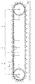
- Figure 1 shows a weighing machine according to the invention.
- Figure 2 shows a perspective bottom view of a plurality of containers to be used in the weighing machine according to the invention.
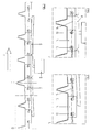
- Figure 3 shows a portion near the weighing device of the weighing machine according to the invention.
- Figures 4 and 5 show portions of the weighing machine shown in Figure 3.
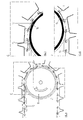
- Figure 6 shows a return wheel of the weighing machine according to the invention, over which the containers are conveyed.
- Figures 7 and 8 show enlarged portions of the return wheel shown in Figure 6.
- FIG. 1 shows a side view of the weighing machine according to the invention.
- the weighing machine comprises a feed portion 1, a weighing portion 2, and a discharge portion 3.
- the discharge portion 3 is divided into several discharge points.
- the weighing machine comprises a first return wheel 4 and a second return wheel 11, around which continuous conveyor means (not shown) and fastened thereto containers 6, are conveyed.
- the return wheels 4, 11 are rotated in the direction of the arrow A. This results in the containers 6 being conveyed in the direction of the arrow B.
- the containers 6 successively pass through the sections 1, 2 and 3.
- At the feed portion 1 the products are put into the containers 6, either manually or automatically.
- section 2 the container 6 and the product therein are weighed with the aid of a weighing device 8.
- the container 6 is subsequently conveyed to the discharge portion 3.
- several collecting means (not shown) are provided, into which the products in the containers 6 may conveniently be deposited. This may be done, for example, with the aid of a blow nozzle (not shown) for blowing the product out of the container.
- a blow nozzle (not shown) for blowing the product out of the container.
- FIG 2 shows a perspective bottom view of three containers.
- Each container 6 consists of a horizontal portion formed by a carrier plate 12, which has two raised edges at its front and rear side (viewed in the direction of movement C).
- each container 6 is provided with two sliding elements 14, comprising openings for the insertion of first connecting elements 13.
- Each of the connecting elements 13 is at its ends connected with conveyor means (not shown).
- Said first connecting means 13 are formed of pins which are positioned substantially perpendicularly to the direction of conveyance of the conveyor means and which are inserted through openings in the container. In the situation depicted, the containers are carried by the first connecting means 13.
- the front openings in the sliding elements through which the first connecting meets are inserted are at the top side provided with a recess allowing the containers, in the direction of movement, to be fixed to the first connecting means. This makes a forward or rearward displacement in relation to the first connecting means impossible.
- the second connecting means 15 In the embodiment depicted, the same consists of a cord fed through guides in the sliding elements. The cord is connected with its ends to the rear one of the first connecting means of the preceding container. When the container is supported by the first connecting means, there will be little or no stress on the second connecting means. In that case the containers will be moved forward mainly by the conveyor means and the first connecting means connected thereto.
- FIG 3 shows the weighing portion of the weighing machine according to the present invention.
- the weighing portion comprises a weighing device 8, a guide 7 positioned before the weighing device 8, and a guide 9 positioned after the weighing device 8.
- the first connecting means 13 With a continuous and substantially linear movement of the conveyor means, the first connecting means 13 will also carry out a substantially linear movement. The course of movement is indicated in the figure by a dashed line. With this linear movement, the containers will initially rest on the first connecting means 13 before the guide 7 is reached, as shown in Figure 4.
- the underside of a sliding element 14 will touch the guide 7, and at a further horizontal movement in the direction of the arrow F as shown in Figure 3, this will result in the assembly comprised of container and, fastened thereunder, the sliding element, being lifted slightly upward. This will result in an uncoupling of the container and the first connecting means 13. Due to the fact that the container is connected by the second connecting means 15 to a first connecting means of the preceding container, said container will be pulled forward without the existence of a direct, rigid coupling between the container and a first connecting means.
- the second connecting means 15 is preferably comprised of a cord or the like, so that the vibrations from the conveyor system will not be transferred to the container.
- Dynamic measurement means that the weight of the container and the product contained therein can be determined while the same are moving in a forward direction.
- the container is conveyed over a second guide 9, arranged at a slightly downward slant, again providing a coupling between the first connecting means and the container. This is illustrated in the right-hand portion of Figure 3.
- Figure 6 shows a return wheel 11, which rotates in the direction of the arrow H.
- the containers are conveyed to the return wheel, they are guided over a guide 10, practically in the same manner shown for the weighing device illustrated in the Figures 3 to 5.
- This brings the containers to a slightly raised position so that when the containers approach the return wheel 11, the underside of the sliding elements 14 is on a plane with the circumferential surface of the return wheel 11.
- This provides a very still and silent admission of the sliding elements 14 of the container 6 on the return wheel 11.
- the openings in the slide blocks 14 are provided with a recess for receiving the first connecting means 13. This fixes the containers 6 to the leading first connecting means 13 when the same are conveyed over the return wheel 11.
- the surface of the return wheels is provided with a rubber coating. This also ensures a gradual conveyance. The result of this is that less noise and less vibration will be generated in the machine. Due to the first connecting means being pressed against the underside of the openings in the container, the sliding elements of the containers will at an appropriate positioning in height become pressed slightly into the rubber surface of the return wheels. This prevents the containers during their conveyance over the return wheels from undergoing an axial displacement.
- the second connecting means 15 are preferably comprised of one cord.
- the problem arises of the container 6 being pulled askew over the weighing device 8. This occurs even when there is a very small discrepancy between the length of the left and right second connecting means. This could result in an incorrect determination of the weight.
- the weighing machine may be adapted and modified as shown in the drawings and explained in the above description, without falling outside the scope of the invention.
- the guides for the second connecting means may comprise separately provided eyes fastened to the sliding elements, or they may be fastened directly to the carrier plate.
- the second connecting means are not fastened to the first connecting means but, for example, to the carrier plate of the preceding container.
- centring means may be applied such that in the proximity of the weighing device, the movement of the continuous conveyor means, for instance a chain, is a linear movement. Due to the first connecting means being fastened directly to the conveyor means, and the containers being uncoupled therefrom by the guides 7, 9, it is possible to obtain a definite separation between the conveyor means. Additionally it is possible to provide centring means for the containers, which ensure that the containers remain in a central position between the conveyor means. These may in particular be provided in the portion upstream from the weighing device to ensure that the containers are centred when being conveyed over the weighing device. Said centring means are preferably not applied at the weighing portion in order not to cause any undesirable vibrations during weighing. Such centring means may also be provided upstream from the return wheels to ensure that the containers are centred when being conveyed over the return wheels.
- tiltable containers In that case the products do not need to be blown out of the containers, but will be removed by tilting the containers.
- the use of such containers is known in the art.
- the coupling of the containers with the conveyor means may further be realized by providing just a foremost or just a hindmost first connecting means.
- guides will then be applied, for example, guide wheels that merely passively support and guide the container.
- one first connecting means that has a suitable unround outline, such as a triangle or a sheet form and which is inserted in a suitably shaped opening in the container. In this way a forward or rearward tilting of the container can be prevented.
Landscapes
- Physics & Mathematics (AREA)
- General Physics & Mathematics (AREA)
- Engineering & Computer Science (AREA)
- Mechanical Engineering (AREA)
- Sorting Of Articles (AREA)
Applications Claiming Priority (2)
| Application Number | Priority Date | Filing Date | Title |
|---|---|---|---|
| NL1013955A NL1013955C2 (nl) | 1999-12-24 | 1999-12-24 | Weegsysteem. |
| NL1013955 | 1999-12-24 |
Publications (1)
| Publication Number | Publication Date |
|---|---|
| EP1111352A1 true EP1111352A1 (de) | 2001-06-27 |
Family
ID=19770514
Family Applications (1)
| Application Number | Title | Priority Date | Filing Date |
|---|---|---|---|
| EP00204741A Withdrawn EP1111352A1 (de) | 1999-12-24 | 2000-12-22 | Wägeapparat |
Country Status (2)
| Country | Link |
|---|---|
| EP (1) | EP1111352A1 (de) |
| NL (1) | NL1013955C2 (de) |
Cited By (3)
| Publication number | Priority date | Publication date | Assignee | Title |
|---|---|---|---|---|
| WO2010034388A1 (de) * | 2008-09-24 | 2010-04-01 | Khs Ag | Multifingerwaage |
| WO2017098156A1 (fr) * | 2015-12-09 | 2017-06-15 | Appalette Tourtellier Systemes | Installation d'extraction a débit régulier |
| CN118145272A (zh) * | 2024-04-07 | 2024-06-07 | 青岛兴仪电子设备有限责任公司 | 一种提高动态称重精度的柔性传动装置及方法 |
Citations (4)
| Publication number | Priority date | Publication date | Assignee | Title |
|---|---|---|---|---|
| US3746145A (en) * | 1970-08-13 | 1973-07-17 | Kalle Ag | Bucket unit |
| US4403669A (en) * | 1982-01-18 | 1983-09-13 | Eshet Eilon | Apparatus for weighing continuously-moving articles particularly useful for grading produce |
| FR2523300A1 (fr) * | 1982-03-08 | 1983-09-16 | Mach Calibrage Cond | Dispositif de pesage d'objets tels que fruits, legumes ou analogues |
| FR2540244A1 (fr) * | 1983-01-31 | 1984-08-03 | Tourangelle Anc Ets Boulesteix | Dispositif pour le pesage individuel d'objets tels que fruits, legumes ou analogues |
-
1999
- 1999-12-24 NL NL1013955A patent/NL1013955C2/nl not_active IP Right Cessation
-
2000
- 2000-12-22 EP EP00204741A patent/EP1111352A1/de not_active Withdrawn
Patent Citations (4)
| Publication number | Priority date | Publication date | Assignee | Title |
|---|---|---|---|---|
| US3746145A (en) * | 1970-08-13 | 1973-07-17 | Kalle Ag | Bucket unit |
| US4403669A (en) * | 1982-01-18 | 1983-09-13 | Eshet Eilon | Apparatus for weighing continuously-moving articles particularly useful for grading produce |
| FR2523300A1 (fr) * | 1982-03-08 | 1983-09-16 | Mach Calibrage Cond | Dispositif de pesage d'objets tels que fruits, legumes ou analogues |
| FR2540244A1 (fr) * | 1983-01-31 | 1984-08-03 | Tourangelle Anc Ets Boulesteix | Dispositif pour le pesage individuel d'objets tels que fruits, legumes ou analogues |
Cited By (5)
| Publication number | Priority date | Publication date | Assignee | Title |
|---|---|---|---|---|
| WO2010034388A1 (de) * | 2008-09-24 | 2010-04-01 | Khs Ag | Multifingerwaage |
| US8841565B2 (en) | 2008-09-24 | 2014-09-23 | Khs Gmbh | Multifingered scale |
| EP2342156B1 (de) | 2008-09-24 | 2017-03-15 | KHS GmbH | Multifingerwaage |
| WO2017098156A1 (fr) * | 2015-12-09 | 2017-06-15 | Appalette Tourtellier Systemes | Installation d'extraction a débit régulier |
| CN118145272A (zh) * | 2024-04-07 | 2024-06-07 | 青岛兴仪电子设备有限责任公司 | 一种提高动态称重精度的柔性传动装置及方法 |
Also Published As
| Publication number | Publication date |
|---|---|
| NL1013955C2 (nl) | 2001-06-26 |
Similar Documents
| Publication | Publication Date | Title |
|---|---|---|
| FI82226C (fi) | Foerfarande och anordning foer matning av tryckalster till en separeringsanordning, saerskilt en ilaeggare. | |
| JP2960633B2 (ja) | 検査秤量装置 | |
| JP2002529688A (ja) | 空気圧式高速計量装置 | |
| EP1072328A3 (de) | System zum Einteilen von Gegenständen und Vorrichtung zur Messung der Abmessungen eines Gegenstandes | |
| US20170243429A1 (en) | Empties sorting device and empties return system | |
| CN201084716Y (zh) | Ic料条激光打标机的输送装置 | |
| EP0270969A3 (de) | Förderer mit schwänkbarem Teil, insbesondere für einen automatischen direkten Weichkuchenapparat | |
| GR3019322T3 (en) | Machine for sorting graphic and/or printing products | |
| EP2143333A1 (de) | Teigförderbandwaage und teigwäge- und -schneidvorrichtung | |
| KR20200096585A (ko) | 라벨링될 원통형 제품의 운송 시스템 | |
| US7581637B2 (en) | Feeding device for a packaging machine | |
| WO2009049202A1 (en) | Method and apparatus for weighing fruit on a conveyor | |
| CA2528225A1 (en) | System and method for transferring blanks | |
| NL1013955C2 (nl) | Weegsysteem. | |
| EP0512115A1 (de) | Kontrollwaage mit Aerodynamikkorrektur | |
| JP2019156410A (ja) | 包装装置 | |
| JP4781256B2 (ja) | 充填量検査装置およびその方法 | |
| US7408124B2 (en) | Weighing conveyor | |
| CN217780092U (zh) | 一种磁铁充磁分料装置 | |
| JPH09210754A (ja) | 合成ゴムの計量切断方法及びその装置 | |
| US20090057034A1 (en) | Weighing Device and Method | |
| FI68553B (fi) | Anordning foer foerdelning av sidobraedorna i ett saogverk | |
| NL1007820C2 (nl) | Transportinrichting. | |
| KR101369180B1 (ko) | 제품자동취출용 이송장치 | |
| JP4738839B2 (ja) | 放出ステーション付きの可変容量fifo型貯蔵所 |
Legal Events
| Date | Code | Title | Description |
|---|---|---|---|
| PUAI | Public reference made under article 153(3) epc to a published international application that has entered the european phase |
Free format text: ORIGINAL CODE: 0009012 |
|
| AK | Designated contracting states |
Kind code of ref document: A1 Designated state(s): AT BE CH CY DE DK ES FI FR GB GR IE IT LI LU MC NL PT SE TR |
|
| AX | Request for extension of the european patent |
Free format text: AL;LT;LV;MK;RO;SI |
|
| 17P | Request for examination filed |
Effective date: 20011112 |
|
| AKX | Designation fees paid |
Free format text: AT BE CH CY DE DK ES FI FR GB GR IE IT LI LU MC NL PT SE TR |
|
| 17Q | First examination report despatched |
Effective date: 20030206 |
|
| GRAP | Despatch of communication of intention to grant a patent |
Free format text: ORIGINAL CODE: EPIDOSNIGR1 |
|
| GRAJ | Information related to disapproval of communication of intention to grant by the applicant or resumption of examination proceedings by the epo deleted |
Free format text: ORIGINAL CODE: EPIDOSDIGR1 |
|
| STAA | Information on the status of an ep patent application or granted ep patent |
Free format text: STATUS: THE APPLICATION IS DEEMED TO BE WITHDRAWN |
|
| 18D | Application deemed to be withdrawn |
Effective date: 20040721 |