EP1110891A2 - Flächige Bedruckstoffe verarbeitende Maschine - Google Patents
Flächige Bedruckstoffe verarbeitende Maschine Download PDFInfo
- Publication number
- EP1110891A2 EP1110891A2 EP00124297A EP00124297A EP1110891A2 EP 1110891 A2 EP1110891 A2 EP 1110891A2 EP 00124297 A EP00124297 A EP 00124297A EP 00124297 A EP00124297 A EP 00124297A EP 1110891 A2 EP1110891 A2 EP 1110891A2
- Authority
- EP
- European Patent Office
- Prior art keywords
- rails
- machine according
- chain
- damping
- sheet
- Prior art date
- Legal status (The legal status is an assumption and is not a legal conclusion. Google has not performed a legal analysis and makes no representation as to the accuracy of the status listed.)
- Withdrawn
Links
- 238000012545 processing Methods 0.000 title claims description 8
- 239000000463 material Substances 0.000 title claims description 7
- 238000013016 damping Methods 0.000 claims abstract description 34
- 238000007639 printing Methods 0.000 claims abstract description 31
- 239000004033 plastic Substances 0.000 claims description 5
- 239000013013 elastic material Substances 0.000 claims description 3
- 229920002959 polymer blend Polymers 0.000 claims description 2
- 239000003190 viscoelastic substance Substances 0.000 claims description 2
- 238000013459 approach Methods 0.000 description 9
- 238000012546 transfer Methods 0.000 description 7
- 238000010516 chain-walking reaction Methods 0.000 description 5
- 238000010521 absorption reaction Methods 0.000 description 3
- 239000002826 coolant Substances 0.000 description 3
- 238000013461 design Methods 0.000 description 3
- 229920000800 acrylic rubber Polymers 0.000 description 2
- 230000005540 biological transmission Effects 0.000 description 2
- 239000011248 coating agent Substances 0.000 description 2
- 238000000576 coating method Methods 0.000 description 2
- 239000003086 colorant Substances 0.000 description 2
- 238000000034 method Methods 0.000 description 2
- 230000010152 pollination Effects 0.000 description 2
- 229920000058 polyacrylate Polymers 0.000 description 2
- 229920000297 Rayon Polymers 0.000 description 1
- 238000005452 bending Methods 0.000 description 1
- 230000015572 biosynthetic process Effects 0.000 description 1
- 230000003247 decreasing effect Effects 0.000 description 1
- 238000006073 displacement reaction Methods 0.000 description 1
- 238000010438 heat treatment Methods 0.000 description 1
- 230000010354 integration Effects 0.000 description 1
- 239000002184 metal Substances 0.000 description 1
- 238000007645 offset printing Methods 0.000 description 1
- 238000005192 partition Methods 0.000 description 1
- 230000005855 radiation Effects 0.000 description 1
- 238000000926 separation method Methods 0.000 description 1
- 239000000758 substrate Substances 0.000 description 1
- 238000012549 training Methods 0.000 description 1
- 238000009423 ventilation Methods 0.000 description 1
Images

Classifications
-
- B—PERFORMING OPERATIONS; TRANSPORTING
- B65—CONVEYING; PACKING; STORING; HANDLING THIN OR FILAMENTARY MATERIAL
- B65H—HANDLING THIN OR FILAMENTARY MATERIAL, e.g. SHEETS, WEBS, CABLES
- B65H29/00—Delivering or advancing articles from machines; Advancing articles to or into piles
- B65H29/02—Delivering or advancing articles from machines; Advancing articles to or into piles by mechanical grippers engaging the leading edge only of the articles
- B65H29/04—Delivering or advancing articles from machines; Advancing articles to or into piles by mechanical grippers engaging the leading edge only of the articles the grippers being carried by endless chains or bands
- B65H29/041—Delivering or advancing articles from machines; Advancing articles to or into piles by mechanical grippers engaging the leading edge only of the articles the grippers being carried by endless chains or bands and introducing into a pile
-
- B—PERFORMING OPERATIONS; TRANSPORTING
- B65—CONVEYING; PACKING; STORING; HANDLING THIN OR FILAMENTARY MATERIAL
- B65H—HANDLING THIN OR FILAMENTARY MATERIAL, e.g. SHEETS, WEBS, CABLES
- B65H2402/00—Constructional details of the handling apparatus
- B65H2402/50—Machine elements
- B65H2402/51—Joints, e.g. riveted or magnetic joints
-
- B—PERFORMING OPERATIONS; TRANSPORTING
- B65—CONVEYING; PACKING; STORING; HANDLING THIN OR FILAMENTARY MATERIAL
- B65H—HANDLING THIN OR FILAMENTARY MATERIAL, e.g. SHEETS, WEBS, CABLES
- B65H2404/00—Parts for transporting or guiding the handled material
- B65H2404/30—Chains
- B65H2404/34—Gripper bars bridging at least two chains running synchronously and parallely
- B65H2404/342—Details of guiding
-
- B—PERFORMING OPERATIONS; TRANSPORTING
- B65—CONVEYING; PACKING; STORING; HANDLING THIN OR FILAMENTARY MATERIAL
- B65H—HANDLING THIN OR FILAMENTARY MATERIAL, e.g. SHEETS, WEBS, CABLES
- B65H2515/00—Physical entities not provided for in groups B65H2511/00 or B65H2513/00
- B65H2515/82—Sound; Noise
-
- B—PERFORMING OPERATIONS; TRANSPORTING
- B65—CONVEYING; PACKING; STORING; HANDLING THIN OR FILAMENTARY MATERIAL
- B65H—HANDLING THIN OR FILAMENTARY MATERIAL, e.g. SHEETS, WEBS, CABLES
- B65H2601/00—Problem to be solved or advantage achieved
- B65H2601/50—Diminishing, minimizing or reducing
- B65H2601/52—Diminishing, minimizing or reducing entities relating to handling machine
- B65H2601/521—Noise
-
- B—PERFORMING OPERATIONS; TRANSPORTING
- B65—CONVEYING; PACKING; STORING; HANDLING THIN OR FILAMENTARY MATERIAL
- B65H—HANDLING THIN OR FILAMENTARY MATERIAL, e.g. SHEETS, WEBS, CABLES
- B65H2801/00—Application field
- B65H2801/03—Image reproduction devices
- B65H2801/21—Industrial-size printers, e.g. rotary printing press
Definitions
- the invention relates to a machine that processes flat substrates, especially a sheet-fed printing press, with operational revolving chains and these leading rails.
- Chains are often used as a means of transmission or as a means of transportation and conveyance Commitment.
- machines processing flat printing materials in particular Sheet processing printing machines, they are used, among other things, for Transport of printed sheets, e.g. taken from a printing unit and one Delivery pile are fed.
- There are two in a chain bracket parallel endless chains are provided, each with a drive and a Deflection sprocket run, the two drive and the two Deflection sprockets each have a common axis of rotation.
- Gripper systems with grippers which close the latter automatically and over Switching means are opened.
- the chains are particularly between the Sprockets by means of rails attached to the frame of the printing press guided.
- Chain drives designed in this way lead to considerable Noise when the chains run at high speed and the gripper systems they carry under the influence of Speed changes or changes of direction and of centrifugal forces in the Area of the sprockets changing contacts of the chains with the rails cause which causes the latter to vibrate, the to a sound radiation with unpleasant frequencies and considerable Volume leads.
- DE 34 23 272 A1 is a printing press with a between walls chain drive enclosed in a soundproof manner. Such a disguise the chain drive is, on the one hand, complex and expensive, on the other hand it requires additional ventilation devices to dissipate heat and moisture.
- the invention is based, simple and inexpensive the task Measures to reduce chain running noise a flat Propose printing machine.
- this object is achieved in the machine mentioned at the beginning solved with at least in sections along the rails arranged damping slip, which is clamped between two clamping surfaces is, of which at least a first is formed on the rails.
- the arrangement of the damping coating according to the invention Due to the arrangement of the damping coating according to the invention effective absorption of the vibrations induced by the chains Rails and consequently an effective reduction in chain running noise guaranteed.
- the arrangement of the damping surface under surface pressure ensures that this does not only apply to pressure when the rails vibrate and bending, but especially what is claimed in thrust results in a high vibration absorption capacity.
- the arrangement of the damping coating according to the invention is also therefore particularly effective because vibrations occur directly at their place of origin be dampened.
- the damping covering is preferably made of a soft elastic or viscoelastic material.
- the damping covering is designed with a modulus of elasticity, preferably between 1 N / mm 2 and 1000 N / mm 2, and a shear modulus, preferably between 0.4 N / mm 2 and 100 N / mm 2 .
- the maximum vibration absorption capacity of the damping covering can be adapted to the resonance frequency of the rails and consequently a significant reduction in chain running noise can be achieved.
- the damping covering can for example be made of an elastomeric plastic or one containing at least one elastomeric plastic Polymer blend exist.
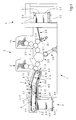
- FIG. 1 is an overall schematic view of a sheet processor Removable machine 1. This has a printing unit section 2, one Paper feed device 3 in the form of a feeder, a boom 4 with a Chain drive 4.1 and one below the end region of the chain drive 4.1 provided stacking station 5.
- the paper feed device 3 has a stack formed from sheets 7 3.1 supporting platform 3.2. For gradual lifting of the same corresponding to the deduction of sheet 7 from the stack 3.1 is one with lifting chains 3.3 working hoist provided. Above the stack 3.1 is one Separating unit 3.4 with lifting and dragging suction cups for gripping the each top sheet 7 of the stack 3.1 and for transferring such Sheet 7 to a transport and a suction belt conveyor Alignment unit 3.5 is provided, which the sheet 7 at its leading as well one side edge of the same for transmission.
- the printing unit section 2 has two in the exemplary embodiment shown printing units 2a, 2 'working according to the offset method and is consequently at Designed to print two colors. To print more colors is for one color each to provide a further printing unit.
- the printing unit 2a has a printing cylinder 2.1 and one with the latter cooperating blanket cylinder 2.2 and one in each Printing unit to be printed sheets to the printing cylinder 2.1 Feed drum 2.3 on.
- the printing unit 2 ' is with appropriate facilities fitted.
- a sheet transfer device 2.5 is located between the printing units 2a, 2 ' intended. If two by such a sheet transfer facility connected printing units the same side of a sheet - with different Color printing, so the sheets are handed over by her; insofar as two connected by such a sheet transfer device Printing units print on the other side of a sheet, that is corresponding sheet transfer device designed such that the sheets turned over to the subsequent printing unit.
- a drive 2.6 with a motor driven Belt drive and a drive gear 2.7 provided, which with a Gear of the sheet transfer device 2.5 is engaged.
- the chain drive 4.1 and the Paper feed device 3 with the drive 2.6 in operative connection in order to Stopping the printing units 2a, 2 'stopping the rest of the Loading the press with sheets or participating in their output Components.
- the printed sheets 7 are on the here with the drive 2.6 in Transfer chain link 4.1 of boom 4 to the active connection. For this are integrated in a gear train of the printing press Drive sprockets 4.2 provided.
- the chain drive 4.1 comprises two endless chains 4.5.
- the chains 4.5 run each along one belonging to a frame of the printing press Side wall of the boom 4 and are formed by a rail 6 Chain guide performed, which is described in detail below.
- a each of the chains 4.5 wraps around one of two during operation synchronously rotating drive sprockets 4.2, whose axes of rotation are aligned, and is in the present embodiment over a Drive sprockets 4.2 downstream with respect to the processing direction arranged deflection sprocket 4.4 out. In the present example they are sitting Drive sprockets 4.2 on a common sprocket shaft 4.3.
- the sheets 7 are of the lower one in FIG Chain center transported.
- the section of the Chain track follows one facing this, on a sheet guiding unit 4.6 trained sheet guiding surface 4.7. Between the latter and each a sheet 7 of air is preferably formed above it.
- the sheet guiding unit 4.6 which ends in the sheet guiding surface 4.7 Blown air nozzles 4.8 equipped, for which only one representative in Fig. 1 for their entirety and in a symbolic representation.
- the Bow brake 4.9 includes a plurality of brake modules, each are preferably formed by means of a suction belt conveyor.
- the sheets 7 are transferred from the chain drive 4.1 to the stacking station 5, so that a stack 5.1 of sheets 7 is formed in it.
- the stacking station 5 has in its upper receiving area for the sheet 7 Front edge stop 5.2 and an opposite one Back edge stop 5.3 through which the sheets 7 are aligned. Furthermore, the stacking station 5 has a lifting mechanism, of which only in FIG. 1 a platform 5.4 carrying the stack 5.1 and carrying it, dash-dotted lines indicated lifting chains 5.5 are reproduced.
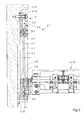
- Fig. 2 is only a part of one of the synchronously guided endless chains 4.5 and one of the gripper systems 4.15 carried by these, which is shown here in rotated and broken representation.
- the Chain 4.5 is guided by a rail 6, the one shown here Design with the formation of dividing surfaces 6.1 'and 6.2' divided longitudinally is formed and an outer guide member 6.1 and an inner one Guide member 6.2 includes.
- the orbit of chain 4.5 is outward from the outer 6.1 and internally bounded by the inner guide member 6.2, the guide members 6.1, 6.2 overall a substantially C-shaped Form the guide profile 6.3 for the chain 4.5.
- the damping pad 6.5 is pressed between the same Guide members 6.1, 6.2 arranged, the pressure by tightening the Screws 6.4 against stops (not shown) is built up.
- the Partition surfaces 6.1 'and 6.2' thus form trained on the rail 6 Clamping surfaces between which the cushioning pad 6.5 is clamped.
- a chain drive 4.1 with such a damped rail 6 causes one Noise reduction of the boom 4 (Fig. 1) by 6 to 10 dB (A).
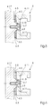
- Fig. 3 shows a partial section along the line A-A in Fig. 1 in another preferred embodiment of a chain drive 4.1 with an example here one-piece rail 6, which has a substantially C-shaped guide profile 6.3 Guide of the chain 4.5 has.
- the rail 6 is interposed Damping pad 6.5 from a flexible, especially soft and / or viscose elastic material, e.g. Acrylic rubber, on one Contact surface 4.18 of a side wall associated with a frame of the machine fixed with screws 6.6.
- the damping pad 6.5 is under pressure arranged between the rail 6 and the side wall 4.17, the pressure is adjustable by means of the screws 6.6 and the adjustment the rail 6 with respect to the side wall 4.17 also by means of Screws 6.6 takes place, which expediently in the adjusted state Are secured.
- the damping covering 6.5 is either in sections Direction of the conveyor chain 6.5 arranged between the screws 6.6 or formed in one piece and penetrated by the screws 6.6, and each clamped between two clamping surfaces, of which a first on the Rail 6 is formed, while a second of the same Contact surface 4.18 is shown.
- the embodiment variant of a chain drive 4.1 shown in FIG. 4 differs from the embodiment according to FIG. 3 in that the Rail 6 via adjustment lugs 6.10 on the same directly on the Contact surface 4.18 of the side wall 4.17 is screwed, the rail 6 automatically when the adjustment lugs 6.10 are applied to the contact surface 4.18 is adjusted.
- the clamped between the rail 6 and the side wall 4.17 Damping pad 6.5 is in the embodiment shown as an example integrally formed and provided with breakthroughs by the Approaches 6.10 are dealt with.
- the thickness D of the cushioning 6.5 in unstressed state (indicated by dashed lines) at least slightly exceeds the thickness d of the approach 6.10, so that the damping pad 6.5 in the assembled Condition is under pressure and effectively dampens the chain drive 4.1.
- the Damping pad 6.5 is thus again between two clamping surfaces clamped, of which a first is formed on the rail 6 and one second of the stop surface 4.18 is shown.
- Figures 3 and 4 thus represent configurations, in each of which one first of the two clamping surfaces that clamp the damping covering 6.5 the rail 6 and a second one on the one frame of the machine associated side wall 4.17 is formed.
- FIG. 5 is a substantially C-shaped guide profile 6.3 for the Chain 4.5 shown rail 6 shown on the raised Attachment approaches 6.9 of the side wall 4.17 using screws 6.7 is immediately attached.
- contact surfaces 4.18 Attachment approaches 4.9 are in particular in compliance with the required Tolerances edited so that the rail 6 when in contact with the Attachment approaches 6.9 is automatically adjusted.
- a respective rail 6 are in the example shown on the Gripper systems 4.15 on the opposite side with damping pads 6.5 applied, the sides facing away from the rails 6 by means of clamping plates 6.8 a rigid material, e.g. Metal or plastic, under pressure the damping pads 6.5 are attached to the rails 6.
- the damping pad 6.5 and Clamping plates 6.8 also extend over the attachment lugs 6.9. In in this case, corresponding recesses are provided, which by the Attachment approaches 6.9 are reached.
Landscapes
- Engineering & Computer Science (AREA)
- Mechanical Engineering (AREA)
- Discharge By Other Means (AREA)
- Feeding Of Articles By Means Other Than Belts Or Rollers (AREA)
- Framework For Endless Conveyors (AREA)
Abstract
Description
- Fig. 1
- eine schematische Gesamtansicht einer Ausführungsform einer Bogen verarbeitenden Maschine in Form einer Offset-Druckmaschine mit einen Kettentrieb bildenden betriebsmäßig umlaufenden Ketten und diese führenden Schienen;
- Fig. 2
- einen Teilschnitt entlang der Linie A-A der Fig. 1 in teilweise gedrehter Darstellung;
- Fig. 3
- einen Teilschnitt entlang der Linie A-A der Fig. 1 bei einer anderen Ausführungsform des Kettentriebs,
- Fig. 4
- einen Teilschnitt entlang der Linie A-A der Fig. 1 bei einer Ausführungsvariante zu Fig. 3;
- Fig. 5
- einen Teilschnitt entlang der Linie A-A der Fig. 1 bei einer weiteren Ausführungsform eines Kettentriebs und
- Fig. 6
- einen Teilschnitt entlang der Linie A-A einer Ausführungsvariante zu Fig. 5.
- 1
- Bogen verarbeitende Maschine
- 2
- Druckwerksabschnitt
- 2a, 2'
- Druckwerke
- 2.1
- Druckzylinder
- 2.2
- Gummituchzylinder
- 2.3
- Anlegetrommel
- 2.4
- Vorgreifer
- 2.5
- Bogentransfereinrichtung
- 2.6
- Antrieb
- 2.7
- Abtriebszahnrad
- 3
- Papierzuführeinrichtung
- 3.1
- Stapel
- 3.2
- Stapelunterlage
- 3.3
- Hubkette
- 3.4
- Vereinzelungseinheit
- 3.5
- Transport- und Ausrichteinheit
- 4
- Ausleger
- 4.1
- Kettentrieb
- 4.2
- Antriebskettenrad
- 4.3
- Kettenradwelle
- 4.4
- Umlenkkettenrad
- 4.5
- Kette
- 4.6
- Bogenleiteinheit
- 4.7
- Bogenleitfläche
- 4.8
- Blasluftdüse
- 4.9
- Bogenbremse
- 4.10
- Trockner
- 4.11
- Bestäubungseinrichtung
- 4.12
- Einlass-Stutzen
- 4.13
- Auslass-Stutzen
- 4.14
- Kühlmittelwanne
- 4.15
- Greifersystem
- 4.16
- Greifer
- 4.17
- Seitenwand des Auslegers
- 4.18
- Anlagefläche
- 5
- Stapelstation
- 5.1
- Stapel
- 5.2
- Vorderkantenanschlag
- 5.3
- Hinterkantenanschlag
- 5.4
- Plattform
- 5.5
- Hubkette
- 6
- Schiene
- 6.1
- äußeres Führungsglied
- 6.1'
- Trennfläche
- 6.2
- inneres Führungsglied
- 6.2'
- Trennfläche
- 6.3
- Führungsprofil
- 6.4
- Schraube
- 6.5
- Dämpfungsbelag
- 6.6
- Schraube
- 6.7
- Schraube
- 6.8
- Klemmplatte
- 6.9
- Befestigungsansatz
- 6.10
- Justieransatz
- 6.11
- Schraube
- 7
- Bogen
- D
- Dicke des Dämpfungsbelages 6.5
- d
- Dicke des Justieransatzes 6.10
Claims (9)
- Flächige Bedruckstoffe verarbeitende Maschine, insbesondere eine Bogen verarbeitende Druckmaschine, mit betriebsmäßig umlaufenden Ketten und diese führenden Schienen,
gekennzeichnet durch
einen wenigstens abschnittweise entlang der Schienen (6) angeordneten Dämpfungsbelag (6.5), der zwischen zwei Klemmflächen eingespannt ist, von welchen wenigstens eine erste an den Schienen (6) ausgebildet ist. - Maschine nach Anspruch 1,
dadurch gekennzeichnet,
das eine zweite der beiden Klemmflächen an einem die Schienen (6) tragenden Gestell (Seitenwand 4.17) ausgebildet ist. - Maschine nach Anspruch 1,
gekennzeichnet durch
wenigstens abschnittweise entlang der Schienen (6) angeordnete und mit diesen unter Zwischenlage des Dämpfungsbelages (6.5) unter Pressung desselben verbundene Klemmplatten (6.8). - Maschine nach Anspruch 1
dadurch gekennzeichnet,
dass die Schienen (6) in deren Längsrichtung verlaufende Trennflächen (6.1', 6.2') aufweisen und die Trennflächen (6.1' und 6.2') die Klemmflächen bilden. - Maschine nach Anspruch 1,
dadurch gekennzeichnet,
dass der Dämpfungsbelag (6.5) aus einem weichelastischen Material besteht. - Maschine nach Anspruch 1,
dadurch gekennzeichnet,
dass der Dämpfungsbelag (6.5) aus einem viskoelastischen Material besteht. - Maschine nach Anspruch 1,
dadurch gekennzeichnet,
dass der Dämpfungsbelag (6.5) aus einem elastomeren Kunststoff oder einem wenigstens einen elastomeren Kunststoff enthaltenden Polymer-Blend besteht. - Maschine nach einem der Ansprüche 1 bis 7,
dadurch gekennzeichnet,
dass das Material des Dämpfungsbelages (6.5) je nach Resonanzfrequenz der Schiene (6) einen Elastizitätsmodul zwischen etwa 1 N/mm2 und 1000 N/mm2 aufweist. - Maschine nach einem der Ansprüche 1 bis 7,
dadurch gekennzeichnet,
dass das Material des Dämpfungsbelages (6.5) je nach Resonanzfrequenz der Schiene (6) einen Schubmodul zwischen etwa 0,4 N/mm2 und 100 N/mm2 aufweist.
Applications Claiming Priority (2)
| Application Number | Priority Date | Filing Date | Title |
|---|---|---|---|
| DE19961883 | 1999-12-20 | ||
| DE19961883 | 1999-12-20 |
Publications (2)
| Publication Number | Publication Date |
|---|---|
| EP1110891A2 true EP1110891A2 (de) | 2001-06-27 |
| EP1110891A3 EP1110891A3 (de) | 2002-09-18 |
Family
ID=7933718
Family Applications (1)
| Application Number | Title | Priority Date | Filing Date |
|---|---|---|---|
| EP00124297A Withdrawn EP1110891A3 (de) | 1999-12-20 | 2000-11-15 | Flächige Bedruckstoffe verarbeitende Maschine |
Country Status (4)
| Country | Link |
|---|---|
| US (1) | US20010013290A1 (de) |
| EP (1) | EP1110891A3 (de) |
| JP (1) | JP2001219539A (de) |
| DE (1) | DE10056727A1 (de) |
Family Cites Families (5)
| Publication number | Priority date | Publication date | Assignee | Title |
|---|---|---|---|---|
| DE3122035A1 (de) * | 1981-05-29 | 1982-12-16 | Chemaperm GmbH, 4714 Selm | "magnetischer rutschfoerderer" |
| DE3939250C1 (de) * | 1989-11-28 | 1990-12-13 | Miller-Johannisberg Druckmaschinen Gmbh, 6222 Geisenheim, De | |
| US5060788A (en) * | 1990-03-28 | 1991-10-29 | Portec, Inc. | Chain guide mounting apparatus |
| DE19513420A1 (de) * | 1995-04-08 | 1996-10-10 | Heidelberger Druckmasch Ag | Kettentrieb |
| DE19637683A1 (de) * | 1996-09-05 | 1998-03-12 | Mannesmann Ag | Kettenförderer |
-
2000
- 2000-11-15 EP EP00124297A patent/EP1110891A3/de not_active Withdrawn
- 2000-11-15 DE DE10056727A patent/DE10056727A1/de not_active Withdrawn
- 2000-12-20 JP JP2000386608A patent/JP2001219539A/ja active Pending
- 2000-12-20 US US09/742,132 patent/US20010013290A1/en not_active Abandoned
Also Published As
| Publication number | Publication date |
|---|---|
| DE10056727A1 (de) | 2001-06-21 |
| US20010013290A1 (en) | 2001-08-16 |
| EP1110891A3 (de) | 2002-09-18 |
| JP2001219539A (ja) | 2001-08-14 |
Similar Documents
| Publication | Publication Date | Title |
|---|---|---|
| EP1136263A2 (de) | Vorrichtung zum Transport eines Bogens für eine Rotationsdruckmaschine | |
| EP1882661A2 (de) | Bogenbremsensystem zum Bremsen von Druckbogen | |
| DE102004030277B4 (de) | Vorrichtung zur Förderung von Bogen durch eine drucktechnische Maschine | |
| DE102008042901B4 (de) | Bogenbremse einer bogenverarbeitenden Maschine, insbesondere Druckmaschine, und ein Verfahren zum Ablegen von Bogen | |
| DE10205213B4 (de) | Ausleger für eine flächige Bedruckstoffe verarbeitende Maschine | |
| EP1397255A1 (de) | Qualitätskontrollvorrichtung | |
| DE19856372B4 (de) | Bogentransportband | |
| DE3126103C2 (de) | ||
| EP1136409B1 (de) | Vorrichtung zum Abbremsen von Probe- und Fehlerbogen einer Bogen verarbeitenden Maschine | |
| CH616619A5 (de) | ||
| EP1110891A2 (de) | Flächige Bedruckstoffe verarbeitende Maschine | |
| EP0527406B1 (de) | Bogenfördereinrichtung in Aus- bzw. Anlegern von Druckmaschinen | |
| EP0275882B1 (de) | Fördervorrichtung für eine Bogenrotationsdruckmaschine | |
| DE10304617B4 (de) | Bogenförderer für eine Bogen verarbeitende Maschine | |
| DE4213472C2 (de) | Vorrichtung zum Fördern flexibler Druckformen | |
| DE102005012527A1 (de) | Anlegeeinheit für eine Bogenverarbeitungsmaschine, Bogenverarbeitungsmaschine und Verfahren zum Anlegen von Bogen | |
| DE4445041C2 (de) | Vorrichtung zum Ausrichten von Bogen | |
| DE19941633C2 (de) | Verfahren und Einrichtung zum Einstellen und Wechseln von Saugringen | |
| DE102006052412B4 (de) | Trommel zum Fördern eines Bogens | |
| DE10224299B4 (de) | Ausleger einer flächige Bedruckstoffe verarbeitenden Maschine | |
| DE10206890B4 (de) | Druckwerk mit einer Vorrichtung zum Entsorgen von Partikeln | |
| DD253020A1 (de) | Leiteinrichtung in auslegern von bogendruckmaschinen | |
| DE102005015793A1 (de) | Vorrichtung zum Fördern von Bogen durch eine drucktechnische Maschine | |
| DE10056245B4 (de) | Schmutzabstreifer | |
| DE10101129B4 (de) | Vorrichtung zum Reduzieren von Schallemissionen |
Legal Events
| Date | Code | Title | Description |
|---|---|---|---|
| PUAI | Public reference made under article 153(3) epc to a published international application that has entered the european phase |
Free format text: ORIGINAL CODE: 0009012 |
|
| AK | Designated contracting states |
Kind code of ref document: A2 Designated state(s): AT BE CH CY DE DK ES FI FR GB GR IE IT LI LU MC NL PT SE TR |
|
| AX | Request for extension of the european patent |
Free format text: AL;LT;LV;MK;RO;SI |
|
| PUAL | Search report despatched |
Free format text: ORIGINAL CODE: 0009013 |
|
| AK | Designated contracting states |
Kind code of ref document: A3 Designated state(s): AT BE CH CY DE DK ES FI FR GB GR IE IT LI LU MC NL PT SE TR |
|
| AX | Request for extension of the european patent |
Free format text: AL;LT;LV;MK;RO;SI |
|
| 17P | Request for examination filed |
Effective date: 20020822 |
|
| 17Q | First examination report despatched |
Effective date: 20021209 |
|
| AKX | Designation fees paid |
Designated state(s): AT BE CH CY DE DK ES FI FR GB GR IE IT LI LU MC NL PT SE TR |
|
| STAA | Information on the status of an ep patent application or granted ep patent |
Free format text: STATUS: THE APPLICATION IS DEEMED TO BE WITHDRAWN |
|
| 18D | Application deemed to be withdrawn |
Effective date: 20030701 |