EP1110620A1 - Wandsegment für eine Wand einer Kabine - Google Patents
Wandsegment für eine Wand einer Kabine Download PDFInfo
- Publication number
- EP1110620A1 EP1110620A1 EP00125638A EP00125638A EP1110620A1 EP 1110620 A1 EP1110620 A1 EP 1110620A1 EP 00125638 A EP00125638 A EP 00125638A EP 00125638 A EP00125638 A EP 00125638A EP 1110620 A1 EP1110620 A1 EP 1110620A1
- Authority
- EP
- European Patent Office
- Prior art keywords
- infill
- frame
- clamping profile
- wall segment
- profile element
- Prior art date
- Legal status (The legal status is an assumption and is not a legal conclusion. Google has not performed a legal analysis and makes no representation as to the accuracy of the status listed.)
- Withdrawn
Links
- 229910001220 stainless steel Inorganic materials 0.000 claims abstract description 22
- 239000010935 stainless steel Substances 0.000 claims abstract description 22
- XAGFODPZIPBFFR-UHFFFAOYSA-N aluminium Chemical compound [Al] XAGFODPZIPBFFR-UHFFFAOYSA-N 0.000 claims abstract description 7
- 229910052782 aluminium Inorganic materials 0.000 claims abstract description 7
- 239000000463 material Substances 0.000 claims description 6
- 239000003973 paint Substances 0.000 claims description 5
- 238000007789 sealing Methods 0.000 description 15
- 238000005260 corrosion Methods 0.000 description 7
- 230000007797 corrosion Effects 0.000 description 7
- 239000000853 adhesive Substances 0.000 description 6
- 230000001070 adhesive effect Effects 0.000 description 6
- 239000010408 film Substances 0.000 description 6
- 239000011521 glass Substances 0.000 description 5
- XLYOFNOQVPJJNP-UHFFFAOYSA-N water Substances O XLYOFNOQVPJJNP-UHFFFAOYSA-N 0.000 description 5
- 239000000945 filler Substances 0.000 description 4
- 239000012790 adhesive layer Substances 0.000 description 3
- 239000002390 adhesive tape Substances 0.000 description 3
- 238000005452 bending Methods 0.000 description 2
- 238000004140 cleaning Methods 0.000 description 2
- NIXOWILDQLNWCW-UHFFFAOYSA-M Acrylate Chemical compound [O-]C(=O)C=C NIXOWILDQLNWCW-UHFFFAOYSA-M 0.000 description 1
- 239000004821 Contact adhesive Substances 0.000 description 1
- 230000001154 acute effect Effects 0.000 description 1
- 239000008367 deionised water Substances 0.000 description 1
- 229910021641 deionized water Inorganic materials 0.000 description 1
- 230000003670 easy-to-clean Effects 0.000 description 1
- 239000003292 glue Substances 0.000 description 1
- 238000009434 installation Methods 0.000 description 1
- 238000000034 method Methods 0.000 description 1
- 235000011837 pasties Nutrition 0.000 description 1
- 239000004588 polyurethane sealant Substances 0.000 description 1
- 230000003716 rejuvenation Effects 0.000 description 1
- 239000007921 spray Substances 0.000 description 1
- 239000010409 thin film Substances 0.000 description 1
Images




Classifications
-
- B—PERFORMING OPERATIONS; TRANSPORTING
- B05—SPRAYING OR ATOMISING IN GENERAL; APPLYING FLUENT MATERIALS TO SURFACES, IN GENERAL
- B05B—SPRAYING APPARATUS; ATOMISING APPARATUS; NOZZLES
- B05B16/00—Spray booths
- B05B16/40—Construction elements specially adapted therefor, e.g. floors, walls or ceilings
Definitions
- the present invention relates to a wall segment for a Wall of a cabin, in particular a cabin of a paint shop, one infill frame, one on the infill frame kept infill and at least one at the Interior of the cabin facing side of the wall segment arranged Clamp profile element, by means of which the infill is fixed to the infill frame.
- the clamping profile element is formed as an aluminum extruded profile.
- Aluminum only conditionally against corrosive media, as they are used in particular in a booth of a paint shop Use, for example, compared to fully desalinated Water (demineralized water), is resistant and the clamping profile element on the inside of the cabin facing the front of the Arranged wall segments and thus this corrosion-promoting Exposed to media is the operational security of such Wall segments affected under unfavorable operating conditions and makes cleaning the wall segment difficult.
- the present invention is therefore based on the object a wall segment for a wall of a cabin of the aforementioned Way of creating which is high operational safety has and is easy to clean.
- a clamping profile element made of stainless steel also has high resistance under unfavorable operating conditions against corrosion-promoting media, for example against fully desalinated water.
- the Filling out the wall segment from a material with high corrosion resistance, especially made of stainless steel or glass is made. If the wall segment has several infills includes, it is particularly advantageous if all infills made of a material with high corrosion resistance, especially made of stainless steel or glass.
- the stainless steel used for the clamping profile element can in particular a stainless steel according to grade 1.4301 DIN 17007.
- the infill frame of the wall segment comprises frame elements, made of a material with a lower specific weight are made of stainless steel.
- the frame elements can be made of aluminum his.
- the infill and the infill on the Infill frame defining clamping profile element or die Infill on the infill frame fixing clamping profile elements the infill frame to the interior of the cabin cover completely. This ensures that only the infill and the clamping profile elements in the interior corrosion-promoting used in the cabin Media are exposed, but not the frame elements of the Infill frame, so that for the frame elements of the infill frame Materials can be used, which have a lower corrosion resistance than stainless steel, without the operational safety and cleanability of the wall segment.
- the clamping profile element one in its longitudinal direction essentially constant, hat-shaped cross-section having.
- a U-shaped cross section Area of the clamping profile element as a holding area for Setting the clamping profile element on the infill frame serve while protruding laterally from this holding area Areas of the clamping profile element as terminal strip areas for Setting the infill on the infill frame can serve.
- the clamping profile element according to the invention can be made from a stainless steel sheet produced by folding and / or roll forming his.
- Cabin walls 102 are made up of individual, essentially tabular wall segments 104 are assembled, which extends from a cabin floor 106 to a cabin ceiling 108 extend.
- the cabin floor 106 is formed by a grid, below which is the usual circulation and cleaning equipment in spray booths are located.
- the cabin ceiling 108 is made of individual, substantially tabular Ceiling elements 112 assembled together form a filter mat arrangement, which in turn one Floor of the so-called plenum 114, which forms above the cabin is arranged.
- each includes tabular ones Wall segments 104 a rectangular profile frame 116, the vertically aligned post when assembled 118 and horizontally aligned bolts in the assembled state 120.
- Posts 118 and transoms 120 are summarized below referred to as frame elements 121.
- the left post 118a, the right post 118b, the bottom latch 120a and the middle latch 120b of the Profile frame 116 together a infill 122a for a lower infill 124a.
- left post 118a form the right post 118b, the middle bar 120b and the top bar 120c together an infill frame 122b for an upper infill 124b.
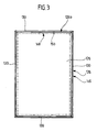
- each of the infills 124 each have the shape of a Rectangular plate having infill element 126 and one arranged along the edges of the infill element 126 rectangular mounting frame 128 that is mitred from four cut mounting frame profiles 130 is composed.
- each of the mounting frame profiles 130 an outer area 132 with a substantially rectangular cross section and an inner region 134 with a essentially trapezoidal cross-section, the Backs 136 and 138 of the outer area 132 and the inner area, respectively 134 are flush with each other while the front 140 of the outer area 132 in front of the front 142 of the inner area 134 is arranged.
- Inner side 144 of inner region 134 runs underneath at an acute angle to the front 142 of the interior 134, so that the inner region 134 of the mounting frame profile 130 from the front 142 to the rear 138 rejuvenated.
- connection area 146 of the mounting frame 128 The outer areas 132 of the four mounting frame profiles 130 form together a connection area 146 of the mounting frame 128.
- Adhesive layer 152 is the infill element 126 and the receiving area 148 of the mounting frame 128 permanently elastic with each other connected.
- a double-sided adhesive can also be used Contact adhesive tape for connecting the infill element 126 provided with the receiving area 148 of the mounting frame 128 his.
- the infill element 126 has a height and a width that are slightly less than the height or width of the Receiving area 148 of the mounting frame 128, so that between upper, lower and lateral outer surfaces 156 of the infill element 126 on the one hand and over the front 150 of the receiving area 148 protruding inner sides 158 of the Connection area 146 of the mounting frame 128 on the other hand a gap 160 remains.
- the infill 124 is on four sides the respective associated infill 122 held releasably.
- the post 118 has one Front wall 162 on, from the front 164 two of them spaced, each in the vertical longitudinal direction of the post 118 extending clamping profile channel side walls Project forward 166a and 166b.
- the side walls 166a and 166b form one between them Clamp profile channel 168, in the in the assembled state in Cross-section U-shaped holding area 170 in the vertical longitudinal direction of the post 118 extending Clamping profile element 172 immersed.
- the areas arranged outside the clamping profile channel 168 the front side 164 of the post 118 form contact surfaces 199 for the mounting frame 128.
- the clamping profile element 172 has one in its longitudinal direction constant hat-shaped cross-section based on a Stainless steel sheet strips by folding or using a Roll-forming process is made.
- the clamping profile element 172 includes one in its longitudinal direction extending, strip-shaped retaining strip area 174, which in the assembled state of the clamping profile element 172 aligned parallel to the front 164 of the post 118 and in one in the middle of the front wall 162 of the post 118 provided in the vertical longitudinal direction of the post extending centering groove 175 is added.
- the width of the holding area 170 corresponds to that Width of the centering groove 175 so that the clamping profile element 172nd through centering groove 175 in one with respect to the front wall 162 of the post 118 is held in the central position.
- each of the side areas 178a, 178b borders along a further folding line 180a or 180b in each case one in the longitudinal direction of the clamping profile element 172 extending, double-folded terminal strip area 182a or 182b, the terminal strip areas 182a, 182b substantially perpendicular to the side areas 178a, 178b are aligned and substantially parallel to the front 164 of the post 118 from the longitudinal median plane 184 of the clamping profile element 172, with respect to which the clamping profile element 172 is mirror-symmetrical, extend away.
- the folding lines 176a, 176b and 180a, 180b no exact lines in the mathematical Senses, but as curved areas with finite width educated.
- the terminal strip areas overlap 182a, 182b of the clamping profile element 172 each one of sidewalls 166a, 166b, with a rear face 186 of each Terminal strip area 182a, 182b on the front edge the associated clamping profile channel side wall 166a, 166b is present.
- the holding strip area 174 of the clamping profile element 172 is with several, in the vertical longitudinal direction of the clamping profile element 172 spaced through holes 188 provided, which in the assembled state of the clamping profile element 172 with threaded blind holes 190 aligned in the Front wall 162 of the post 118 are provided.
- the through holes 188 are each by a fastening screw 192 interspersed, the one with an external thread provided shaft 194 screwed into one of the threaded blind holes 190 and its screw head 196 on the front of the retaining strip area 174 abuts so that the clamping profile element 172 between the screw head 196 and the front 164 of the front wall 162 of the post 118 clamped is.
- At an outer edge area of the rear side 186 of the terminal strip area 182a is one from the front sides 140 of FIG Outside areas 132 of the mounting frame profiles 130 formed Front 198 of the connection area 146 of the mounting frame 128 via a separating film 200 arranged in between, so that the connecting portion 146 of the mounting frame 128 between the front wall 162 of the post 118 on the one hand and the Terminal strip area 182a of the clamping profile element 172, on the other hand is jammed.
- the gap 160 is between the Infill element 126 on the one hand and the mounting frame 128 and the clamping profile element 172 on the other hand with one a filler, for example from a polyurethane sealant, Filled sealing element 202 filled, the the sealing of the to the front of the infill element 126 adjacent interior of the cabin against the outside serves the same.
- a filler for example from a polyurethane sealant, Filled sealing element 202 filled
- connection area 146 of the mounting frame 128 and the terminal strip area 182a arranged separating film 200 is prevented that the filler in the joint between the connection area 146 and the terminal strip area 182a creeps and after they have hardened into one Glue the mounting frame 128 to the clamping profile element 172 leads.
- the separating film 200 can be formed by an elastic band to compensate for tolerances on the clamping of the To reach infill 124 on the infill frame 122.
- the elastic band For Simplification of flush installation of the elastic Band on the clamping profile element 172 can the elastic band be designed to be adhesive on one side.
- the infill element 126 is made using an adhesive or a double-sided adhesive tape on the recording area 148 of the mounting frame 128 glued on.
- the infill 124 is then in the associated infill frame 122 arranged that the rear 197 of the connection area 146 of the mounting frame 128 on the contact surfaces 199 the post 118 of the infill frame 122 abuts.
- the rear sides 186 of the terminal strips 182a, 182b of the associated clamping profile elements 172 with the separating film 200 provided, for example, in that the release film 200 as one-sided adhesive elastic tape on the terminal strip areas 180a, 180b is applied.
- clamping profile elements 172 on each associated post 118 arranged that the terminal strip areas 182a, 182b over the release film 200 at the connection area 146 of the mounting frame 128 and the backs of the Retaining strip areas 174 on the front sides 164 of the front walls 162 of the respective posts 118 abut, and the clamping profile elements 172 are in this position using the fastening screws 192, which is screwed into the threaded blind holes 190 be secured.
- column 160 is filled with the filler, to form the sealing elements 202.
- the infill is 124 fully assembled in the infill frame 122.
- clamping profile elements 172 made of stainless steel for example made of stainless steel of grade 1.4301 according to DIN 17007 they also have high corrosion resistance then on when operating the cabin with corrosive Media, for example with demineralized water (Deionized water).
- the posts 118 and the transoms 120 of the profile frame 116 are on the other hand made of a material that is less Has specific weight as stainless steel, so that Total weight of the cabin 100 is reduced.
- the posts 118 and transoms 120 are preferably the profile frames 116 therefore made of aluminum.
- One and the same frame element 121 can be part of several Infill frame 122.
- both are between the back 186 of the first Terminal strip area 182a and the first contact surface 199a of the relevant frame element 121 as well as between the rear side 186 of the second terminal strip area 182b and of the second contact surface 199b of the frame element 121 in each case a connection area 146 of the mounting frame of a first one Infill 128 or a second infill clamped.
- the arrangement of two infills on the same frame element 121 is preferably used when the Frame element 121 is a horizontal bar 120.
- the frame element 121 is one vertical posts 118, so to arrange several infills side by side preferably two vertical Posts 118a, 118b arranged side by side so that these two posts facing each other, flat lateral Contact surfaces 206 abut each other, the two Posts 118a and 118b with respect to a common longitudinal median plane 208, in which the contact surfaces 206 also lie, are formed and arranged mirror-symmetrically to each other (see Fig. 5).
- the gap between the two posts 118a, 118b is thereby sealed by means of two sealing elements 209, which as elastic hollow tubes with semicircular cross-section trained and with their flat sides on one of each Profile channel side walls 166a, 166b are glued and with their curved sides abut each other.
- Each of the posts 118a and 118b is constructed as above described, and in particular comprises a clamping profile element 172a or 172b for clamping a infill 124a or infill 124b.
- the two encounter each other neighboring, through the centering grooves 175 on the respective Center the front wall 162 of the posts 118a and 118b Clamping profile elements 172a and 172b on the facing one another Narrow sides of the terminal strip areas 182b or 182a to one another and are the front faces 204 of these terminal strip areas flush with each other, so that the two clamping profile elements 172a, 172b of the adjacent vertical posts 118a, 118b together a continuous bar made of stainless steel form.
- a second embodiment shown in detail in FIG. 6 of a wall segment for a cabin differs from the first embodiment described above in that the infills in the second embodiment not, as in the first embodiment, by means of a mounting frame are held releasably on the infill frame, but rather by means of between the infill element and the Frame element on the one hand and between the infill element and the clamping profile element on the other hand arranged sealing elements.
- the infill 124 includes the second embodiment of a wall segment 100 only the infill element 126.
- Every frame element for example every post 118, has one in the assembled state on the front of the infill element 126 adjacent front sealing element 210 on.
- Each clamping profile element 172 has one in the assembled state rear lying against the back of the infill element 126 Sealing element 212.
- Each of the sealing elements 210, 212 extends longitudinally an edge of the infill element 126 and has in it Longitudinal direction an essentially constant trapezoidal Cross section on which the infill element 126 opposite side of the respective sealing element 210, 212 tapered towards.
- each of the sealing elements 210, 212 each one in recess 214 or 216 extending in the longitudinal direction thereof on which has a substantially rectangular cross section having.
- the recess 214 of the front sealing element 210 takes the outer edge of the terminal strip area when assembled 182a of the clamping profile element 172 and is on the same, for example by means of a double-sided adhesive tape with an acrylate adhesive.
- the recess 216 of the rear sealing element 212 takes in the assembled state, the area bearing the contact surface 199a the front wall 162 of the post 118 and is on the same, for example by means of a double-sided adhesive tape, fixed.
- the thickness of the sealing elements 210, 212 is dimensioned so that that the infill element 126 between the front wall 162 of the post 118 and the terminal strip area 182a of the Clamping profile element 172 with the sealing elements arranged thereon 210, 212 under elastic prestressing of the Sealing elements 210, 212 is clamped.
- the second embodiment of a wall segment is correct in terms of structure and function with the first embodiment of a wall segment, on the above Description so far.
Landscapes
- Load-Bearing And Curtain Walls (AREA)
- Building Environments (AREA)
Abstract
Description
- Fig. 1
- eine perspektivische Darstellung einer Kabine einer Lackieranlage;
- Fig. 2
- eine Vorderansicht eines Wandsegments der Kabine aus Fig. 1;
- Fig. 3
- eine Vorderansicht einer einen Montagerahmen umfassenden Ausfachung des Wandsegments;
- Fig. 4
- einen horizontalen Schnitt durch einen vertikalen Pfosten und eine Ausfachung des Wandsegments;
- Fig. 5
- einen horizontalen Schnitt durch die vertikalen Pfosten und Ausfachungen zweier einander benachbarter Wandsegmente; und
- Fig. 6
- einen der Darstellung der Fig. 4 entsprechenden horizontalen Schnitt durch einen vertikalen Pfosten und eine Ausfachung einer zweiten Ausführungsform eines Wandsegments.
Claims (7)
- Wandsegment für eine Wand einer Kabine (100), insbesondere einer Kabine einer Lackieranlage, umfassend einen Ausfachungsrahmen (122), eine an dem Ausfachungsrahmen gehaltene Ausfachung (124) und mindestens ein an der dem Innenraum der Kabine zugewandten Seite des Wandsegments (100) angeordnetes Klemmprofilelement (172), mittels dessen die Ausfachung (124) an dem Ausfachungsrahmen (122) festgelegt ist,
dadurch gekennzeichnet, daß
das Klemmprofilelement (172) aus Edelstahl hergestellt ist. - Wandsegment nach Anspruch 1, dadurch gekennzeichnet, daß der Ausfachungsrahmen (122) Rahmenelemente (121) umfaßt, die aus einem Material mit einem geringeren spezifischen Gewicht als Edelstahl hergestellt sind.
- Wandsegment nach Anspruch 2, dadurch gekennzeichnet, daß die Rahmenelemente (121) aus Aluminium hergestellt sind.
- Wandsegment nach einem der Ansprüche 1 bis 3, dadurch gekennzeichnet, daß die Ausfachung (124) und das die Ausfachung (124) an dem Ausfachungsrahmen (122) festlegende Klemmprofilelement (172) oder die die Ausfachung (124) an dem Ausfachungsrahmen (122) festlegenden Klemmprofilelemente (172) den Ausfachungsrahmen (122) zum Innenraum der Kabine (100) hin vollständig überdecken.
- Wandsegment nach einem der Ansprüche 1 bis 4, dadurch gekennzeichnet, daß das Klemmprofilelement (172) einen in seiner Längsrichtung im wesentlichen konstanten, hutförmigen Querschnitt aufweist.
- Wandsegment nach einem der Ansprüche 1 bis 5, dadurch gekennzeichnet, daß das Klemmprofilelement aus einem Edelstahlblech durch Abkanten hergestellt ist.
- Wandsegment nach einem der Ansprüche 1 bis 5, dadurch gekennzeichnet, daß das Klemmprofilelement (172) aus einem Edelstahlblech durch Rollumformen hergestellt ist.
Applications Claiming Priority (2)
| Application Number | Priority Date | Filing Date | Title |
|---|---|---|---|
| DE29922478U | 1999-12-22 | ||
| DE29922478U DE29922478U1 (de) | 1999-12-22 | 1999-12-22 | Wandsegment für eine Wand einer Kabine |
Publications (1)
| Publication Number | Publication Date |
|---|---|
| EP1110620A1 true EP1110620A1 (de) | 2001-06-27 |
Family
ID=8083317
Family Applications (1)
| Application Number | Title | Priority Date | Filing Date |
|---|---|---|---|
| EP00125638A Withdrawn EP1110620A1 (de) | 1999-12-22 | 2000-11-23 | Wandsegment für eine Wand einer Kabine |
Country Status (2)
| Country | Link |
|---|---|
| EP (1) | EP1110620A1 (de) |
| DE (1) | DE29922478U1 (de) |
Citations (3)
| Publication number | Priority date | Publication date | Assignee | Title |
|---|---|---|---|---|
| EP0302428A1 (de) * | 1987-08-07 | 1989-02-08 | Diego Da Col | Rahmenlose Verglasung |
| DE19739642A1 (de) * | 1997-09-10 | 1999-03-25 | Eisenmann Kg Maschbau | Wand für die Kabine einer Lackieranlage |
| EP0941771A2 (de) * | 1998-03-13 | 1999-09-15 | Dürr Systems GmbH | Wandsegment für eine Kabinenkonstruktion |
-
1999
- 1999-12-22 DE DE29922478U patent/DE29922478U1/de not_active Expired - Lifetime
-
2000
- 2000-11-23 EP EP00125638A patent/EP1110620A1/de not_active Withdrawn
Patent Citations (3)
| Publication number | Priority date | Publication date | Assignee | Title |
|---|---|---|---|---|
| EP0302428A1 (de) * | 1987-08-07 | 1989-02-08 | Diego Da Col | Rahmenlose Verglasung |
| DE19739642A1 (de) * | 1997-09-10 | 1999-03-25 | Eisenmann Kg Maschbau | Wand für die Kabine einer Lackieranlage |
| EP0941771A2 (de) * | 1998-03-13 | 1999-09-15 | Dürr Systems GmbH | Wandsegment für eine Kabinenkonstruktion |
Also Published As
| Publication number | Publication date |
|---|---|
| DE29922478U1 (de) | 2000-05-04 |
Similar Documents
| Publication | Publication Date | Title |
|---|---|---|
| EP0363725B1 (de) | Siebboden | |
| DE4015166C2 (de) | Verglastes Gebäudeteil | |
| DE4040006A1 (de) | Glaswand | |
| DE19739644C2 (de) | Wand für die Kabine einer Lackieranlage | |
| DE10319001B4 (de) | Fassade oder Dach mit mehreren Entwässerungsebenen | |
| EP0298328A1 (de) | Fassadenwand | |
| EP0443190A1 (de) | Befestigung von Rahmen, Platten, Glasscheiben oder dgl. an einer Tragkonstruktion | |
| DE4401667C2 (de) | Abstandshalterrahmen für eine Isolierscheibe und Vorrichtung zu seiner Herstellung | |
| DE69314817T2 (de) | Modul-System für Bauwerkfassaden | |
| DE29922478U1 (de) | Wandsegment für eine Wand einer Kabine | |
| DE2934940A1 (de) | Doppelfenster | |
| DE19811036B4 (de) | Wandsegment für eine Kabinenkonstruktion | |
| DE69815904T2 (de) | Klemmverbindungselement zum Verbinden zweier Wandprofile miteinander | |
| DE9013659U1 (de) | Schutzwand, insbesondere zum Schutz gegen Überfluten durch Hochwasser | |
| DE3623630A1 (de) | Kabinenkonstruktion | |
| EP0231525B1 (de) | Fahrbahnübergang für Dehnfugen bei Eisenbahnbrücken | |
| DE9412899U1 (de) | Handlaufstruktur für Treppenhaus | |
| EP1050488A2 (de) | Containergruppe sowie Verfahren zum Verbinden der Container | |
| DE102023107791A1 (de) | Structural-Glazing-Konstruktion und Verfahren zum Auswechseln einer Isolierglasscheibe einer Structural-Glazing-Konstruktion | |
| AT394616B (de) | Rahmenfoermiges bauelement | |
| DE4204236C1 (de) | ||
| DE3601890A1 (de) | Beschlag fuer glastueren od.dgl. | |
| DE3327950C2 (de) | Rahmenhohlprofil für Fenster-, Tür- und Trennwandelemente | |
| DE3306653C1 (de) | Begrenzungselement für Stallboxen | |
| EP0579107A1 (de) | Isolierglasscheibe für ein Notausstiegsfenster |
Legal Events
| Date | Code | Title | Description |
|---|---|---|---|
| PUAI | Public reference made under article 153(3) epc to a published international application that has entered the european phase |
Free format text: ORIGINAL CODE: 0009012 |
|
| AK | Designated contracting states |
Kind code of ref document: A1 Designated state(s): AT BE CH CY DE DK ES FI FR GB GR IE IT LI LU MC NL PT SE TR |
|
| AX | Request for extension of the european patent |
Free format text: AL;LT;LV;MK;RO;SI |
|
| 17P | Request for examination filed |
Effective date: 20011115 |
|
| RAP1 | Party data changed (applicant data changed or rights of an application transferred) |
Owner name: ROTEC RADEBEULER OBERFLAECHEN-TECHNIK GMBH |
|
| AKX | Designation fees paid |
Free format text: AT BE CH CY DE DK ES FI FR GB GR IE IT LI LU MC NL PT SE TR |
|
| 17Q | First examination report despatched |
Effective date: 20051027 |
|
| GRAP | Despatch of communication of intention to grant a patent |
Free format text: ORIGINAL CODE: EPIDOSNIGR1 |
|
| RAP1 | Party data changed (applicant data changed or rights of an application transferred) |
Owner name: ROTEC SYSTEMS GMBH |
|
| STAA | Information on the status of an ep patent application or granted ep patent |
Free format text: STATUS: THE APPLICATION IS DEEMED TO BE WITHDRAWN |
|
| 18D | Application deemed to be withdrawn |
Effective date: 20080110 |