EP1110557B1 - Method for sterilizing devices in a container - Google Patents
Method for sterilizing devices in a container Download PDFInfo
- Publication number
- EP1110557B1 EP1110557B1 EP00311545A EP00311545A EP1110557B1 EP 1110557 B1 EP1110557 B1 EP 1110557B1 EP 00311545 A EP00311545 A EP 00311545A EP 00311545 A EP00311545 A EP 00311545A EP 1110557 B1 EP1110557 B1 EP 1110557B1
- Authority
- EP
- European Patent Office
- Prior art keywords
- container
- attachable
- detachable
- valve
- detachable container
- Prior art date
- Legal status (The legal status is an assumption and is not a legal conclusion. Google has not performed a legal analysis and makes no representation as to the accuracy of the status listed.)
- Expired - Lifetime
Links
Images


Classifications
-
- A—HUMAN NECESSITIES
- A61—MEDICAL OR VETERINARY SCIENCE; HYGIENE
- A61L—METHODS OR APPARATUS FOR STERILISING MATERIALS OR OBJECTS IN GENERAL; DISINFECTION, STERILISATION OR DEODORISATION OF AIR; CHEMICAL ASPECTS OF BANDAGES, DRESSINGS, ABSORBENT PADS OR SURGICAL ARTICLES; MATERIALS FOR BANDAGES, DRESSINGS, ABSORBENT PADS OR SURGICAL ARTICLES
- A61L2/00—Methods or apparatus for disinfecting or sterilising materials or objects other than foodstuffs or contact lenses; Accessories therefor
- A61L2/16—Methods or apparatus for disinfecting or sterilising materials or objects other than foodstuffs or contact lenses; Accessories therefor using chemical substances
- A61L2/20—Gaseous substances, e.g. vapours
- A61L2/208—Hydrogen peroxide
-
- A—HUMAN NECESSITIES
- A61—MEDICAL OR VETERINARY SCIENCE; HYGIENE
- A61L—METHODS OR APPARATUS FOR STERILISING MATERIALS OR OBJECTS IN GENERAL; DISINFECTION, STERILISATION OR DEODORISATION OF AIR; CHEMICAL ASPECTS OF BANDAGES, DRESSINGS, ABSORBENT PADS OR SURGICAL ARTICLES; MATERIALS FOR BANDAGES, DRESSINGS, ABSORBENT PADS OR SURGICAL ARTICLES
- A61L2/00—Methods or apparatus for disinfecting or sterilising materials or objects other than foodstuffs or contact lenses; Accessories therefor
- A61L2/02—Methods or apparatus for disinfecting or sterilising materials or objects other than foodstuffs or contact lenses; Accessories therefor using physical phenomena
- A61L2/14—Plasma, i.e. ionised gases
-
- A—HUMAN NECESSITIES
- A61—MEDICAL OR VETERINARY SCIENCE; HYGIENE
- A61L—METHODS OR APPARATUS FOR STERILISING MATERIALS OR OBJECTS IN GENERAL; DISINFECTION, STERILISATION OR DEODORISATION OF AIR; CHEMICAL ASPECTS OF BANDAGES, DRESSINGS, ABSORBENT PADS OR SURGICAL ARTICLES; MATERIALS FOR BANDAGES, DRESSINGS, ABSORBENT PADS OR SURGICAL ARTICLES
- A61L2/00—Methods or apparatus for disinfecting or sterilising materials or objects other than foodstuffs or contact lenses; Accessories therefor
- A61L2/16—Methods or apparatus for disinfecting or sterilising materials or objects other than foodstuffs or contact lenses; Accessories therefor using chemical substances
-
- A—HUMAN NECESSITIES
- A61—MEDICAL OR VETERINARY SCIENCE; HYGIENE
- A61L—METHODS OR APPARATUS FOR STERILISING MATERIALS OR OBJECTS IN GENERAL; DISINFECTION, STERILISATION OR DEODORISATION OF AIR; CHEMICAL ASPECTS OF BANDAGES, DRESSINGS, ABSORBENT PADS OR SURGICAL ARTICLES; MATERIALS FOR BANDAGES, DRESSINGS, ABSORBENT PADS OR SURGICAL ARTICLES
- A61L2202/00—Aspects relating to methods or apparatus for disinfecting or sterilising materials or objects
- A61L2202/10—Apparatus features
- A61L2202/12—Apparatus for isolating biocidal substances from the environment
- A61L2202/122—Chambers for sterilisation
-
- A—HUMAN NECESSITIES
- A61—MEDICAL OR VETERINARY SCIENCE; HYGIENE
- A61L—METHODS OR APPARATUS FOR STERILISING MATERIALS OR OBJECTS IN GENERAL; DISINFECTION, STERILISATION OR DEODORISATION OF AIR; CHEMICAL ASPECTS OF BANDAGES, DRESSINGS, ABSORBENT PADS OR SURGICAL ARTICLES; MATERIALS FOR BANDAGES, DRESSINGS, ABSORBENT PADS OR SURGICAL ARTICLES
- A61L2202/00—Aspects relating to methods or apparatus for disinfecting or sterilising materials or objects
- A61L2202/10—Apparatus features
- A61L2202/14—Means for controlling sterilisation processes, data processing, presentation and storage means, e.g. sensors, controllers, programs
-
- A—HUMAN NECESSITIES
- A61—MEDICAL OR VETERINARY SCIENCE; HYGIENE
- A61L—METHODS OR APPARATUS FOR STERILISING MATERIALS OR OBJECTS IN GENERAL; DISINFECTION, STERILISATION OR DEODORISATION OF AIR; CHEMICAL ASPECTS OF BANDAGES, DRESSINGS, ABSORBENT PADS OR SURGICAL ARTICLES; MATERIALS FOR BANDAGES, DRESSINGS, ABSORBENT PADS OR SURGICAL ARTICLES
- A61L2202/00—Aspects relating to methods or apparatus for disinfecting or sterilising materials or objects
- A61L2202/20—Targets to be treated
- A61L2202/24—Medical instruments, e.g. endoscopes, catheters, sharps
Definitions
- This invention relates to a method for sterilizing devices in a container using a source of vaporizable germicide and negative pressure.
- Medical instruments have traditionally been sterilized using either heat, such as is provided by steam, or a chemical, such as formaldehyde or ethylene oxide in the gas or vapor state. Each of these methods has drawbacks. Many medical devices, such as fiberoptic devices, endoscopes, power tools, etc. are sensitive to heat, moisture, or both. Formaldehyde and ethylene oxide are both toxic gases that pose a potential hazard to healthcare workers. Problems with ethylene oxide are particularly severe, because its use requires long aeration times to remove the gas from articles that have been sterilized. This makes the sterilization cycle time undesirably long.
- U.S. Pat. 4,952,370 to Cummings et al discloses a sterilization process wherein aqueous hydrogen peroxide vapor is first condensed on the article to be sterilized, and then a source of vacuum is applied to the sterilization chamber to evaporate the water and hydrogen peroxide from the article.
- This method is suitable to sterilize surfaces, however, it is ineffective at rapidly sterilizing diffusion-restricted areas, such as those found in lumened devices, since it too depends on the diffusion of the hydrogen peroxide vapor into the lumen to effect sterilization.
- U.S. Pat. 4,943,414 entitled “Method for Vapor Sterilization of Articles Having Lumens,” and issued to Jacobs et al., discloses a process in which a vessel containing a small amount of a vaporizable liquid sterilant solution is attached to a lumen, and the sterilant vaporizes and flows directly into the lumen of the article as the pressure is reduced during the sterilization cycle.
- This system has the advantage that the water and hydrogen peroxide vapor are pulled through the lumen by the pressure differential that exists, increasing the sterilization rate for lumens, but it has the disadvantage that the vessel needs to be attached to each lumen to be sterilized. In addition, water is vaporized faster and precedes the hydrogen peroxide vapor into the lumen.
- the invention relates to a method for sterilizing an article under reduced pressure.
- the method is defined in claim 1 and includes placing the articles in a container, where the container has a communication port and where the container is attachable to and detachable from a vacuum source through the communication port.
- the pressure in the container is reduced through the communication port, and germicide vapor is then introduced through said communication port.
- the method also includes detaching the container from the vacuum source.
- the communication port is closed when the container is detached from the vacumm source, to maintain the sterility of the article, and to maintain the pressure in the container.
- the pressure in the container is above or below atmospheric pressure when the container is detached from the vacuum source.
- the diffusion restricted environment is created with a diffusion restricted port.
- the communication port contains a valve.
- the valve is a hinged valve.
- the valve is a septum.
- the method may also include inserting a needlelike device through the septum.
- the method may include attaching at least one additional container to the vacuum source.
- the container and the additional containers each contain an article to be sterilized, and the articles can be sterilized independently, simultaneously, in a synchronized manner, in a asynchronized manner, or in a multitasking manner.
- an second container may be nested inside the first container.
- the second container contains a gas permeable and microbe-impermeable filter.
- the second container is a flexible pouch.
- the germicide vapor contains hydrogen peroxide.
- the communication port contains a valve.
- At least one additional container is attached to the vacuum source.
- the container and the additional container each contain an article to be sterilized, and the articles to be sterilized can be sterilized independently, simultaneously, in a synchronized manner, in a asynchronized manner, or in a multitasking manner.
- a second container containing at least one communication port is nested inside the container.
- the second container contains a gas permeable and microbe-impermeable filter.
- the second container is a flexible pouch.
- Sterilizing the inside of lumened devices has always posed a challenge to sterilization systems. Achieving rapid sterilization of lumened devices or other diffusion restricted articles at low temperatures and low concentrations of sterilant represents an even greater challenge.
- articles to be sterilized are treated with germicide vapor under vacumm. to a vacuum.
- the vapor preferably comprises hydrogen peroxide or peracetic acid vapor.
- the methods of the present invention provide for the rapid sterilization of lumened and non-lumened articles under conditions that will not damage the articles nor leave toxic residues on the sterile articles.
- the article to be sterilized is exposed to a vacuum followed by low temperature plasma for a time sufficient to effect sterilization.
- plasma is intended to include any portion of the gas or vapor that contains electrons, ions, free radicals, dissociated and/or excited atoms or molecules produced as a result of an applied electric field, including any accompanying radiation that might be produced.
- the applied field may cover a broad frequency range; however, a radio frequency or microwaves are commonly used.
- the sterilization methods of the present invention can also be used with plasmas generated by the method disclosed in the previously mentioned U.S. Pat. 4,643,876 .
- the methods of the present invention may be used with plasmas described in U.S. Patent 5,115,166 or 5,087,418 , in which the article to be sterilized is located in a chamber that is separated from the plasma source.
- the present invention provides several advantages over earlier vapor sterilization systems, such as, (1) the rapid sterilization of lumened devices and diffusion restricted articles can be rapidly achieved at low temperatures; (2) the use of concentrated, potentially hazardous, solutions of anti-microbials is avoided; (3) the heed to attach a special vessel to deliver sterilant vapors into long, narrow lumens is eliminated; (4) no toxic residues remain; (5) since the product is dry at the end of the process, sterile storage of these articles can be achieved; (6) closed end lumens can be sterilized; and (7) the process can be repeated as desired without undue effects.
- the method of the present invention therefore provides for a highly efficient, nonhazardous, and relatively inexpensive method of sterilization.
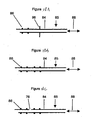
- FIGURES 1 and 2 show two embodiments of attachable/detachable containers 20 as alternative embodiments of diffusion-restricted containers suitable for use in various embodiments of the method of the invention.
- the container 20 comprises two ports 55.
- a first port 55 comprises a reducer 81, where the reducer 81 reduces the diameter of the port 55.
- the reducer 81 may be of any shape.
- the reducer 81 of FIGURE 1 is shaped like a cylinder with a hole along the length of the cylinder.
- a gas-permeable and microorganism-impermeable filter 72 is located inside the bore of the reducer 81.
- the embodiment of the first port 55 shown in FIGURE 1 additionally comprises a valve 82, the valve 82 is optional.
- the diffusion restriction in the container 20 of FIGURE 1 may result from the port 55, the reducer 81, the filter 72, the valve 82, or any combination of the port 55, the reducer 81, the filter 72, and the valve 82.
- the port 55 or the reducer 81 is at least 1.0 cm in length, acting as an entry/exit port and creating diffusion restriction in the container 20.
- the port 55 or reducer 81 has a diameter of 9 mm or less or has an area of 63.62 mm 2 or less, acting as an entry/exit port and creating diffusion restriction in the container 20.
- the second port 55 can be used to create diffusion restriction instead of the first port 55.
- the valve 82 may comprise a gas permeable and microorganism impermeable filter.
- the filter may be in the bore of the valve 82 or in the port 55. The filter prevents microorganisms from entering the container 20 when the system is vented.
- the gas permeable and microorganism impermeable filter is present elsewhere in the system.
- the container 20 comprises two ports 55 and two valves 82.
- the valve 82 further comprises a gas permeable and microorganism impermeable filter in the bore of the valve 82.
- the diffusion restriction in the attachable/detachable container 20 shown in FIGURE 2 may be due to the valve 82, the filter, or a combination of the valve 82 and the filter.
- the embodiment shown in FIGURE 2 shows two ports 55 with two valves 82, the second port 55 and valve 82 are optional. Either, or both, of the two valves 82 can create the diffusion restriction.
- FIGURES 3 and 4 show embodiments of suitable connectors 85 for connecting the attachable/detachable containers 20 shown in FIGURES 1 and 2 to a source of vacuum, fluid and/or other feedthrough 88.
- FIGURE 3 shows a tube 84 with a plurality of O-rings 86 on the inside of one end of the tube 84.
- the O-rings are preferably made of a material which is resistant to degradation by hydrogen peroxide. Suitable materials for fabricating the O-rings include, but are not limited to VITON TM , TEFLON TM , or silicone. In some embodiments, there is only one O-ring 86 inside of the tube 84.
- the second end of the tube 84 is connected to a source of vacuum, fluid, and/or other feedthrough 88.
- the fluid comprises peroxide, preferably hydrogen peroxide or peracetic acid.
- FIGURE 4 shows an alternative embodiment of a connector 85 for connecting the attachable/detachable containers 20 of FIGURES 1 and 2 to the source of vacuum, fluid, and/or other feedthrough 88.
- the embodiment of the connector 85 shown in FIGURE 4 comprises two tubes 84 with two valves 82.
- the tubes 84 comprise a plurality of O-rings 86 inside a first end.
- the embodiment of the connector 85 shown in FIGURE 4 further comprises two sources of vacuum, sources of fluid, and/or other feedthrough 88.
- the two tubes 84 and two sources of vacuum, fluid, and/or other feedthrough 88 can operate independently of one another by closing one or both valves 82. In other embodiments of the connector, only one valve 82 and one source of vacuum, fluid, and/or other feedthrough 88 are present.
- FIGURES 5-7 show various embodiments of attachable/detachable containers 20 connected to the connector 85 of FIGURE 3 .
- the attachable/detachable container 20 has a port 55 with a valve 82,
- the attachable/detachable container 20 of FIGURE 5 is attached to the connector 85 shown in FIGURE 3 .
- the valve 82 may also have a filter in the bore of the valve.
- the diffusion restriction in the attachable/detachable container of FIGURE 5 may be due to the port 55, the valve 82, the filter, or any combination of the port 55, the filter, and the valve 82.
- the attachable/detachable container 20 has a port 55 with a filter 72 and a valve 82.
- the attachable/detachable container 20 is attached to the connector 85 of FIGURE 3 .
- the diffusion restriction in the attachable/detachable container 20 may be due to the valve 82, the filter 72, or the combination of the valve 82 and the filter 72.
- the filter 72 is permeable to gases but impermeable to microorganisms, so that the attachable/detachable container 20 may be vented after sterilization without recontaminating the interior of the attachable/detachable container 20 or any article contained in the attachable/detachable container 20.
- FIGURE 7 shows a attachable/detachable container 20 comprising a filter 72.
- the attachable/detachable container 20 is attached to a connector 85 similar to the connector 85 of FIGURE 3 , except that the connector 85 in FIGURE 7 also comprises a valve 82.
- the valve 82 of the connector 85 is located between the attachable/detachable container 20 and the source of vacuum, fluid, and/or other feedthrough 88.
- the attachable/detachable container 20 may be vented from the source of vacuum, fluid, and/or other feedthrough 88 by opening the valve 82 on the connector 84.
- the diffusion restriction in the attachable/detachable container 20 may be due to the valve 82, the filter 72, or the combination of the valve 82 and the filter 72.
- the filter 72 is preferably permeable to gas but impermeable to microorganisms, so that the attachable/detachable container 20 and any article inside the container 20 are not recontaminated when the attachable/detachable container 20 is vented.
- the attachable/detachable container 20 shown in FIGURE 8 has two ports 55.
- a first port 55 is equipped with a filter 72 and a valve 82.
- a second port 55 has a septum 87.
- the septum 87 is made of flexible plastic or rubber which is impermeable to gases, so that the attachable/detachable container 20 may be evacuated. It is preferred that the plastic or rubber making up the septum 87 is resistant to hydrogen peroxide. Examples of materials suitable for forming the septum include, but are not limited to, VITON TM or silicone.
- the septum is punctured by a needlelike device 89 which is connected to the source of vacuum, fluid, and/or other feedthrough 88.
- the diffusion restriction in the attachable/detachable container 20 may be due to the needlelike device 89 which is acting as an entry/exit port. The entire sterilization process may occur through the needlelike device 89 as the entry/exit port. If the diffusion restriction in the container 20 is due to the needlelike device 89, the diffusion restriction may result from a needlelike device 89 which is at least 1.0 cm in length, has an internal diameter of 9 mm or less, or has a cross sectional area of 63.62 mm 2 or less.
- the first port 55 of the attachable/container 20 shown in FIGURE 8 may optionally be attached to a connector 85 which is attached to the source of vacuum, fluid, and/or other feedthrough 88.
- the diffusion restriction in the attachable/detachable container may be due to the port 55, the filter 72, the valve 82, or any combination of the port 55, the filter 72, and the valve 82.
- the sterilization of the attachable/detachable container 20 may then occur through the first port 55 having the valve 82 and the filter 72.
- the attachable/detachable container 20 of FIGURE 1 is attached to the connector 85 of FIGURE 4 .
- the O-rings 86 on the connector 85 form a vacuum-tight seal with the port 55 of the attachable/detachable container 20.
- the diffusion restriction in the attachable/detachable container 20 in FIGURE 9 can be caused by the port 55, the reducer 81, the filter 72, the valve 82 in the top port 55, the valve 82 in the connector 85, or a combination.
- the diffusion restriction in the attachable/detachable container 20 can be caused by the valve 82 in the bottom port 55 in FIGURE 9 .
- the attachable/detachable container 20 can be exposed to the source of vacuum, fluid, or other feedthrough 88 through the source 88 on the right side of FIGURE 9 or the source 88 at the bottom of FIGURE 9 .
- FIGURE 10 shows the attachable/detachable container 20 of FIGURE 2 attached to the embodiment of the connector 85 of FIGURE 4 .
- the diffusion restriction in the attachable/detachable container 20 can be caused by either or both ports 55 and/or any of the valves 82.
- the source of vacuum, source of fluid, or other feedthrough 88 can be either the source 88 at the right of FIGURE 10 or the source 88 at the bottom of FIGURE 10 .
- an attachable/detachable container 20 having only one port 55 may be attached to one of the two tubes 84 of the embodiment of the connector 85 shown in FIGURE 4 .
- FIGURES 5-10 are meant to be illustrative of various embodiments, and the invention is not limited to the embodiments shown in these Figures.
- Other combinations of attachable/detachable containers 20 and connectors 85 can be used as alternative embodiments of the apparatus and the method of the invention.
- the tube 84 can be smaller than the port 55, and the tube 84 may be inserted into the port 55 with the O-rings on the outside of the tube 84.
- Articles may be sterilized with the embodiments of the attachable/detachable container 20 and connectors 85 shown in FIGURES 1-10 in several embodiments of the method of the invention.
- Plasma may optionally be generated and contacted with the article to be sterilized.
- the attachable/detachable container 20 is vented with a gas.
- the venting comprises passing the gas through a gas permeable and microorganism impermeable filter 72, where the filter is located either on the attachable/detachable container 20 or in another part of the system.
- attachable/detachable container 20 is detached from the connector 85 before venting.
- attachable/detachable container 20 comprises at least one valve 82 and the valve 82 is closed before the attachable/detachable container 20 is separated from the connector 85.
- the attachable/detachable container 20 with the enclosed sterilized article may optionally be transported. Because the valve 82 on the attachable/detachable container 20 is closed, the article in the attachable/detachable container 20 can remain sterile for extended periods of time, because the valve 82 isolates the article from the environment.
- an article is sterilized in an attachable/detachable container 20 comprising a valve 82, and the valve 82 is closed before detaching the attachable/detachable container 82 from the connector 85 and the source of vacuum, fluid, and/or other feedthrough 88.
- the pressure inside the attachable/detachable container 20 after closing the valve 82 and after detaching from the connector 85 is less than atmospheric pressure.
- the valve 82 may be controlled manually or electronically.
- the attachable/detachable container 20 containing the sterilized article is stored for extended periods of time, it is possible that a leak could occur, potentially causing contamination of the sterilized article. If the pressure inside the attachable/detachable container 20 was at less than atmospheric pressure when the valve 82 was closed, a user can test whether the attachable/detachable container leaked by listening for the sound of inflowing gas when the attachable/detachable container 20 is vented by opening the valve 82. If the attachable/detachable container 20 has leaked, the attachable/detachable container will likely be at atmospheric pressure, and the user will not near the sound of inflowing gas when the valve 82 is opened.
- the attachable/detachable container 20 may be pressurized to a pressure greater than one atmosphere.
- the user will hear the sound of outflowing gas when the container 20 is vented by opening the valve 82. If no outflowing gas is heard when the valve 82 is opened, the user will know that a leak has occurred.
- one or more pressure measuring devices such as pressure gauges or transducers are placed on the attachable/detachable container 20.
- the pressure in the attachable/detachable container 20 is measured after sterilization is complete and the container 20 is sealed. If the pressure as measured by the pressure measuring device changes during storage, it may be assumed that the attachable/detachable container 20 leaked during storage.
- the pressure measuring device comprises a transparent valve with movable balls.
- the valve is attached to the attachable/detachable container 20.
- the transparent valve comprises two tubes, an upper tube extending upward from the center of the valve, and a lower tube extending downward from the center of the valve. Both the ends of the tubes and the portion of the tubes next to the center of the valve are constricted to an area smaller than the area of the balls, so that the balls may not pass out of the tubes or go beyond the center of the valve.
- both balls are at the lower ends of the respective tubes.
- the attachable/detachable container 20 is above atmospheric pressure, the ball in the upper tube is forced to the top of the upper tube, next to the constriction.
- the ball in the lower tube is at the bottom of the lower tube, next to the constriction.
- the attachable/detachable container 30 is below atmospheric pressure, both balls are forced next to the restrictions in the center of the valve.
- the pressure indicator comprises a receptacle with a thin film extending across the receptacle.
- the receptacle is attached to the attachable/detachable container 20. If the attachable/detachable container 20 is at atmospheric pressure, the film is neither dilated toward the inside nor toward the outside. If the attachable/detachable container 20 is below atmospheric pressure, the center of the film is sucked inward toward the attachable/detachable container 20. If the attachable/detachable container is above atmospheric pressure, the center of the film is pushed outward, away from the attachable/detachable container 20.
- any of these means of measuring pressure or any other means of pressure indication it is determined whether the attachable/detachable container 20 is above, below, or at atmospheric pressure. If the attachable/detachable container 20 was either above or below atmospheric pressure when the container 20 was stored and is at atmospheric pressure after being stored, the attachable/detachable container 20 almost undoubtedly leaked. Storing the attachable/detachable container 20 at pressures above or below atmospheric pressure with some means of determining pressure is therefore a useful way to determine whether the attachable/detachable container 20 leaked while being stored.
- An article to be sterilized is placed in an attachable/detachable container 20, the attachable/detachable container 20 is attached to a connector 85 which is fluidly connected with the source of vacuum, fluid, and/or other feedthrough 88, and the vaporizable germicide is introduced into the attachable/detachable container 20 from the source of vacuum, fluid, and/or other feedthrough 88 rather than by contacting the attachable/detachable container 20 or the article to be sterilized with the vaporizable germicide.
- the attachable/detachable container 20 is then exposed to reduced pressure to vaporize the germicide, thereby sterilizing the article.
- FIGURE 11 shows an alternative embodiment of the attachable/detachable container 20 in which the attachable/detachable container 20 comprises two ports 55.
- the second port 55 is optional.
- the top port 55 in FIGURE 11 is equipped with reducer 81 with a filter 72 in the bore of the reducer 81, where the filter 72 is gas permeable and microorganism impermeable.
- the top port 55 is also equipped with a hinged valve 90, where the hinged valve 90 comprises a flap 92 on a hinge 94, where the flap 92 has a circular shape, an oval shape, a square shape or any other shape that closes the opening in the port 55.
- the hinge 94 is attached to the interior of the port 55, allowing the flap 92 to open and close by swinging on the hinge 94.
- the flap 92 forms a gas and.vacuum-tight seal with the port 55 when the flap 92 is closed.
- the hinged valve 90 further comprises a spring (not shown) which returns the flap 92 to a closed position when there is no external force on the flap 92 to force the flap 92 open.
- the hinge 94 may be either on a side of the flap 92 inside the attachable/detachable container 20 or on a side of the flap 92 outside of the attachable/detachable container 20. It is generally preferred that the hinge 94 be on the side of the flap 92 inside the attachable/detachable container 20.
- the second port 55 of the embodiment of the attachable/detachable container 20 shown in FIGURE 11 is equipped with a hinged valve 90.
- attachable/detachable containers 20 Pressurizing attachable/detachable containers 20 to pressures above atmospheric pressure after sterilization can allow for detection of leaks, because the user can hear the hiss of the gas escaping the attachable/detachable container 20 when a valve or other device is opened to vent the container 20. If there is no hiss of gas, the attachable/detachable container 20 probably leaked.
- Testing for leaks by pressurizing the container 20 is advantageous with containers with hinged valves 90, because the pressurized gas in the container 20 pushes against the flap 92, sealing the flap 92 firmly in place in the port 55.
- FIGURE 12 shows an alternative embodiment of a connector 85.
- the connector 85 of FIGURE 26 is essentially identical to the connector 85 of FIGURE 4 , with two tubes 84, two sources of vacuum, fluid, and/or other feedthrough 88, and two valves 82.
- the plurality of O-rings 86 are on the outside of the tube 84 rather than on the inside of the tube 84, as in the connector 85 shown in FIGURE 4 .
- one side of the tube 84 is longer than the second side of the tube 84, so that the end of the tube 84 forms a slanted line when viewed from the side.
- the two sides of the tube 84 are of equal length.
- FIGURE 13 shows the attachable/detachable container 20 of FIGURE 11 attached to the connector 85 of FIGURE 12 .
- the upper and lower tubes 84 of the connector 85 are inserted into the hinged valves 90 on the attachable/detachable container 20, opening the flaps 92 on the hinged valves 90.
- the longer side of the tube 84 helps to push the flap 92 aside.
- the plurality of O-rings 86 on the outside of the tubes 84 contact the interior of the ports 55, making a gas and vacuum-tight seal with the interior of the ports 55.
- a stop (not shown) inside one or both of the ports 55 on the attachable/detachable container 20.
- the stop limits the travel of the tube 84 of the connector 85 inside the port 55, so that the tube 84 does not penetrate so far into the port 55 that the O-rings 86 do not contact the inner walls of the port 55 to make the vacuum-tight seal. If the tube 84 extends too far into the port 55, the O-rings 86 would contact the flaps 92, and it is unlikely that the O-rings 86 would seal on the flaps 92.
- the stop can be, for example, a projection on the interior of the port 55 which contacts an end of the tube 84, limiting the travel of the tube 84 into the port 55.
- the optional valves 82 on the connector 85 can be used to isolate one or both of the sources of vacuum, fluid, and/or other feedthrough 88 from the attachable/detachable container 20.
- the connector 85 and attachable/detachable container 20 shown in FIGURE 13 can be separated.
- the flaps 92 on the hinged valves 90 close due to the force of the springs (not shown), forming an air-tight seal with the inner wall of the ports 55, isolating the interior of the attachable/detachable container 20 from the environment.
- the hinged valves 90 of the attachable/detachable container 20 shown in FIGURES 11 and 13 therefore provide a means of automatically isolating the interior of the attachable/detachable container 20 from the environment when the connector 85 is separated from the attachable/detachable container 20.
- FIGURES 14-17 show various embodiments of containers 20 contained inside attachable/detachable containers 20 as “nested containers".
- an inner container 20A is contained inside an attachable/detachable container 20B, where the attachable/detachable container 20B has a valve 82 on the port 55, allowing the attachable/detachable container 20B to be isolated.
- the inner container 20A of FIGURE 14 has a communication port 30 on the top of the container, allowing gas such as germicide vapor to pass from the inner container 20A to the inside of the attachable/detachable container 20B.
- the communication port 30 can be a hole, window, tube, or any other communication port 30 which allows gas or vapor to pass.
- the communication port 30 is either a window which is permeable to gases but impermeable to microorganisms, or the communication port 30 is covered by a filter 72 which allows vapor to pass but does not allow microorganisms to pass.
- the window or filter 72 prevent microorganisms from entering the inner container 20A when the outer attachable/detachable container 20B is vented.
- the inner container 20A may or may not be diffusion restricted.
- the attachable/detachable container 20B is preferably diffusion restricted.
- FIGURE 15 shows an alternative embodiment of nested containers in which the inner container 20A has a substantially horizontal tube 74 as the communication port.
- a filter 72 is placed in the horizontal tube 74, where the filter 72 is permeable to gases but impermeable to microorganisms.
- the horizontal tube 74 allows germicide vapor to flow from the interior of the inner container 20A to the interior of the attachable/detachable container 20B.
- the attachable/detachable container 20B of FIGURE 15 has a port 55 equipped with a hinged valve 90 and a filter 72, where the filter 72 is located between the hinged valve 90 and the interior of the attachable/detachable container 20B.
- the filter 72 is permeable to gases but impermeable to microorganisms.
- the filter 72 allows the attachable/detachable container 20B to be vented without contaminating the interior of the attachable/detachable container 20B or the interior and exterior of the inner container 20A.
- FIGURE 16 shows an alternative embodiment of nested containers in which the inner container 20A is a pouch.
- the pouch in FIGURE 16 contains a non-lumen device 40, a pair of scissors.
- the pouch as the inner container 20A is placed inside an attachable/detachable container 20B.
- the attachable/detachable container 20B of FIGURE 16 has a port 55 with a valve 82.
- the diffusion restriction in the attachable/detachable container 20B may be due to the port 55, the valve 82, or a combination of the port 55 and the valve 82.
- at least a portion of the pouch as an inner container 20A is made of a gas permeable barrier such as TYVEK TM .
- TYVEK TM and CSR wrap barrier are permeable to gases, including hydrogen peroxide vapor.
- the balance of the pouch can be made of a gas impermeable barrier such as MYLAR TM .
- a device to be sterilized is placed into the pouch as inner container 20A.
- a vaporizable germicide such as liquid comprising hydrogen peroxide is placed inside the attachable/detachable container 20B, the pouch as the inner container 20A, or both the attachable/detachable container 20B and the pouch, and a vacuum is applied to the attachable/detachable container 20B to vaporize the vaporizable germicide.
- the germicide vapor passes through the gas permeable portion of the pouch, either into or out of the pouch, depending on where the vaporizable germicide was placed, to sterilize the device, the interior and exterior of the pouch as an inner container 20A, and the interior of the attachable/detachable container 20B.
- a plasma may be generated and flowed into the attachable/detachable container 20B.
- the device in the pouch can be either a non-lumen device or a lumen device. Depending on the length and internal diameter of the lumen, liquid pretreatment of the interior of the lumen may be required.
- FIGURE 17 shows an inner container 20A having a port 55 with a hinged valve 90 closed by a flap 92 attached to the inside of the port 55 with a hinge 94.
- the hinged valve 90 also has a spring (not shown) which forces the flap 92 closed when there is no pressure on the flap 92.
- the inner container 20A also has a communication port 30 on the top of the container 20A, where the communication port 30 is covered by a filter 72, where the filter 72 is permeable to gases but impermeable to microorganisms.
- the communication port 30 can be a hole, a tube, a window, a rectangular shaped opening, or any other opening. There is no need for the inner container 20A to be diffusion restricted.
- the inner container 20A is placed in an attachable/detachable containers 20B with a hinged valve 90 on a port 55.
- the hinged valve 90 on the attachable/detachable container 20B is similar to the hinged valve on the inner container 20A.
- the communication port 30 on the inner container 20A allows vacuum or germicide vapor to be transmitted from the inside of the inner container 20A to the inside of the attachable/detachable container 20B.
- the inner container 20A is placed between two retaining guides 96 attached to the inside of the attachable/detachable container 20B.
- the retaining guides 96 fit snugly against the outside of the inner container 20A, securing and retaining the inner container 20A in a fixed position inside the attachable/detachable container 20B.
- the retaining guides 96 can have various shapes.
- the retaining guides 96 are long flaps attached to the inner wall of the outer attachable/detachable container 20B.
- the retaining guides 96 are narrow strips that fit into slots on the outside of the inner attachable/detachable container 20B.
- Other embodiments of retaining guides 96 will be apparent to those skilled in the art.
- retaining guides 96 are optional, having retaining guides 96 on the inside of the attachable/container 20B is a preferred embodiment, because the retaining guides 96 hold the inner container 20A firmly in position inside the attachable/detachable container 20B.
- FIGURE 18A shows an embodiment of a connector 85 which may be connected to the container 20B of FIGURES 15 and 17 .
- the connector 85 comprises a tube 84 with a plurality of O-rings 86 attached to the outside of the tube 84.
- One end of the tube 84 is fluidly connected to a source of vacuum, fluid, and/or other feedthrough 88.
- the connector 85 optionally, but preferably, has a stop 98 on the outside of the tube 84.
- the stop 98 contacts the end of the port 55 and prevents the tube 84 from extending too far into the interior of the attachable/detachable container 20B.
- the stop 98 insures that the plurality of O-rings 86 are in the proper position to form a good seal with the inside of the port 55. If the O-rings 86 were to contact the flap 92 rather the interior of the port 55, it is probable that the O-rings 86 would not be able to form a vacuum-tight seal.
- the stop 98 limits the travel of the connector 85 when the stop 98 contacts the end of the port 55.
- the connector 85 of FIGURE 18A may also be used with the attachable/detachable container 20B shown in FIGURE 17 or any other container 20 having a hinged valve 90.
- the connector 85 of FIGURE 18A may also be used with attachable/detachable containers having a valve 82 in the port 55, by inserting the tube 84 into the port 55.
- the O-rings 86 on the outside of the tube 84 would form a seal with the inside surface of the port 55.
- FIGURE 18B shows a connector 85 suitable for attaching to the nested containers 20A and 20B shown in FIGURE 17 .
- the connector 85 of FIGURE 18B is similar to the connector 85 of FIGURE 18A in comprising a tube 84 with a plurality of O-rings 86 attached to the outside of the tube 84.
- the connector 85 of FIGURE 18B has four O-rings 86 rather than the two O-rings 86 for the connector 85 of FIGURE 18A . The purpose of the four O-rings will become clear when FIGURES 19A and 19B are described.
- One end of the tube 84 is fluidly connected to a source of vacuum fluid, and/or other feedthrough 88.
- the connector 85 shown in FIGURE 18B does not have a stop as does the connector 85 shown in FIGURE 18A , some embodiments of the connectors 85 of FIGURE 18A do have a stop.
- the connector of FIGURE 18C is identical to the connector of FIGURE 18B , except that there is a hole 76 in the tube 84 on the connector 85 of FIGURE 18C in between the second and the third O-rings 86.
- the purpose of the hole 76 will be become clear when FIGURE 19B is described.
- the connectors 85 of FIGURES 18A, 18B and 18C are shown with ends of one side of the tube 84 being longer than the second side of the tube 84, so that the end of the tube 84 forms a slanted line when viewed from the side.
- the two sides of the tube 84 are of equal length.
- FIGURES 19A and 19B show how the connectors 85 of FIGURES 18B or 18C attach to the nested containers 20A and 20B of FIGURE 17 .
- FIGURE 19A shows the connector 85 of FIGURE 18B inserted into the hinged valve 90 of the attachable/detachable container 20B of FIGURE 17 .
- the flap 92 is pushed aside against the force of the spring (not shown), exposing the interior of the attachable/detachable container 20B to the source of vacuum, source of fluid, and/or other feedthrough 88.
- the plurality of O-rings 86 on the outside of the tube 84 form a vacuum-tight seal with the inside of the port 55 of the attachable/detachable container 20B.
- FIGURE 19B shows how the connector 85 of either FIGURE 18B or 18C can be inserted into both the hinged valve 90 of the inner container 20A and the hinged valve 90 of the attachable/detachable container 20B.
- the plurality of O-rings 86 on the outside of the tube 84 form vacuum-tight seals with the inside of the ports 55 of the inner container 20A and the attachable/detachable container 20B.
- the stop 98 on the outside of the connector 85 would contact the end of the port 55 on the attachable/detachable container 20B, limiting the movement of the tube 84 so that the O-rings 86 are in contact with the inside of the two ports 55.
- the retaining guides 96 hold the inner container 20A in place inside the outer attachable/detachable container 20B when the connector 85 of FIGURE 18B or FIGURE 18C is pushed through the hinged valves 90. If the connector 85 of FIGURE 18C is used, where there is a hole 76 between the first two and the last two O-rings 86, the hole 76 is located between the port 55 of the inner container 20A and the port 55 of the attachable/detachable container 20B after the connector 85 is inserted into the two ports 55. Although the hole 76 can be oriented in any manner, in a preferred embodiment, the hole 76 in the tube 84 is oriented upwards.
- the hole 76 is oriented upwards, fluid which is introduced into the tube 84 from the source of vacuum, fluid, and/or other feedthrough 88 can travel through the tube 84 into the interior of the inner container 20A. and does not pass through the hole 76.
- the hole 76 on the connector 85 of FIGURE 18C allows the attachable/detachable container 20B to be evacuated through the connector 85. If the connector 85 of FIGURE 18C is used with the nested containers 20A and 20B shown in FIGURE 17 , it is not necessary to have the communication port 30 on the inner container 20A, because the inner container 20A can be evacuated through the connector 85, and the attachable/detachable container 20B can be evacuated through the hole 76 in the connector. If desired, hydrogen peroxide vapor or mist can be introduced into the inner container 20A through the connector 85 and the attachable/detachable container 20B through the hole 76 on the connector 85 of FIGURE 18C .
- germicide such as peroxide is transferred from the source of vacuum, fluid, and/or other feedthrough through the connector 85 into the inner container 20A rather than being placed directly into the inner container 20A or being contacted with the article to be sterilized in the inner container 20A.
- Plasma may optionally be introduced into either or both of the containers in any of the embodiments of the method of the invention.
- the germicide in the inner container 20A and/or in the attachable/detachable container 20B by properly placing the germicide in the inner container 20A and/or in the attachable/detachable container 20B, the interior and the exterior of the inner container 20A, the interior of the outer attachable/detachable container 20B, and the article in the inner container 20A are all sterile.
- the nested containers containing a sterile article can be transferred to an area close to an operating room.
- the outer container 20B can be opened and the inner container 20A removed. Because the exterior of the inner container 20A is sterile, the inner container 20A containing the sterile article can be transferred into a sterile environment such as an operating room without contaminating the sterile environment.
- the sterile article inside the sterile inner container 20A can be removed from the container and utilized at leisure without concern about contamination from the container in which it is housed.
- FIGURES 20A, 20B, and 20C schematically illustrate systems for sterilizing one, two, and four attachable/detachable containers, respectively.
- a single attachable/detachable container 20 is attached to a system 100 for sterilizing attachable/detachable containers.
- the system 100 comprises a source of vacuum, fluid, and/or other feedthrough 88.
- the system 100 may further comprise one or more heaters (not shown) for heating the attachable/detachable container 20 and/or a source of vaporizable germicide or peroxide (not shown).
- the system 100 may additionally comprise a source of plasma (not shown) and/ or one or more filters (not shown), where the filters are permeable to gas and impermeable to microorganisms.
- the attachable/detachable container 20 is attached to the system 100.
- the attachable/detachable container 20 preferably contains an article to be sterilized.
- the attachable/detachable container 20 is in fluid communication with the system 100.
- Plasma may optionally be introduced into the attachable/detachable container 20 before, during, and/or after the germicide is introduced into the attachable/detachable container 20. If the plasma is introduced prior to introducing the peroxide or germicide, the plasma helps to dry the article to be sterilized and/or the interior of the attachable/detachable container 20.
- the plasma helps to sterilize the article inside the attachable/detachable container 20 as well as the interior of the attachable/detachable container 20.
- the plasma also helps to remove the residual in the container.
- FIGURE 20B shows a schematic diagram of a system 100 for sterilizing two attachable/detachable containers 20.
- the system 100 comprises a source of vacuum, fluid, and/or other feedthrough 88.
- two attachable/detachable containers 20 may be sterilized simultaneously.
- the system 100 for sterilizing two attachable/detachable containers 20 may comprise two separate sources of vacuum, fluid, and/or other feedthrough 88
- the system 100 comprise a single source of vacuum, fluid, and/or other feedthrough 88
- the source of vacuum, fluid, and/or other feedthrough further comprises one or more valves 82 between the source of vacuum, fluid, and/or other feedthrough 88 and the attachable/detachable containers 20 so that a first attachable/detachable container 20 can be attached and detached from the system 100 without interfering with the operations which are occurring on a second attachable/detachable container 20.
- the system 100 may further comprise one or more heaters for heating the two attachable/detachable containers 20 and/or a source of germicide or peroxide (not shown).
- the system 100 may additionally comprise one or more sources of plasma (not shown).
- the system 100 may additionally comprise one or more filters (not shown), where the filters are permeable to gas and impermeable to microorganisms.
- the two attachable/detachable containers 20 may therefore be sterilized at different times or under different conditions.
- the attachable/detachable containers 20 may be sterilized independently of one another, in a synchronized manner, in an asynchonized manner, or in a multitasking manner with at least one vacuum source.
- FIGURE 20C shows a schematic diagram of a system 100 for sterilizing four attachable/detachable containers 20.
- each of the four attachable/detachable containers 20 in the system 100 can be attached, detached, and sterilized independently.
- the attaching, detaching, and sterilization of each of the attachable/detachable containers 20 occurs simultaneously with the attaching, detaching, and sterilization of the other attachable/detachable containers 20.
- performing the operations on each of the attachable/detachable containers 20 simultaneously with the operations on the other containers would minimize redundant equipment, flexibility is lost. For example, if there is only one vacuum system for the four containers, equipment costs would be minimized. However, it may take a longer time to multitask and sterilize all four attachable/detachable containers 20.
- the attachable/detachable containers 20 may be sterilized independently of one another, in a synchronized manner, in an asynchonized manner, or in a multitasking manner with at least one vacuum source.
- articles can be sterilized in attachable/detachable containers 20 without the need to place the articles in a large vacuum chamber.
- an individual article to be sterilized can be placed into an attachable/detachable container 20, attached to a system 100, and can be sterilized at any time, rather than having to wait until enough equipment has been accumulated to make it worthwhile to sterilize a large load in a large sterilization chamber. Sterilizing an article in an attachable/detachable container 20 therefore provides flexibility in scheduling sterilization of individual articles.
- sterilizing an article in an attachable/detachable container 20 provides flexibility in varying the sterilization conditions. For example, if an article is to be sterilized with an unusual set of conditions, it may be sterilized in an attachable/detachable container 20 without having to sterilize an entire large load under the same set of conditions in a large sterilization chamber.
- the sterilized article is contained inside the attachable/detachable container 20 after being sterilized.
- the attachable/detachable container 20 with the sterilized article inside may be transported large distances inside the attachable/detachable container 20 without a need to be concerned that the article become accidentally contaminated by being exposed to bacteria.
- the sterilized article is protected from contamination by being contained in the attachable/detachable container 20.
- the attachable/detachable container 20 which is sterilized in the system 100 can be a nested container 20, as shown, for example, in FIGURES 14-17 .
- the sterilized article is contained in the inner container 20A, which is in turn contained in the outer attachable/detachable container 20B. Because both the inside and the outside of the inner container 20A are sterile, the outer attachable/detachable container 20B can be transported to an area near to an operating room, the inner container 20A removed, and the sterile inner container 20A with the sterile article inside placed in a sterile area such as an operating room without having concerns about contaminating the sterile area with a nonsterilized container.
- attachable/detachable container 20 and the sterilization system shown in FIGURES 20A, 20B, and 20C therefore provide additional scheduling convenience and flexibility compared to conventional sterilization systems.
- FIGURES 20A, 20B, and 20C In the embodiments of the attachable/detachable container 20 can be any kind of container and is not necessarily diffusion restricted.
- the process is as follows. An article to be sterilized is placed into the attachable/detachable container 20.
- the container 20 is attached to a vacuum source. The placing and attaching can be in either order.
- the attachable/detachable container 20 is evacuated, and germicide vapor is introduced into the attachable/detachable container 20, sterilizing the article and the inside of the attachable/detachable container 20.
- the container 20 with the sterilized article may be detached from the vacuum source.
- Plasma may optionally be introduced into the attachable/detachable container 20 before, during, and/or after the germicide vapor is introduced into the attachable/detachable container 20. If the plasma is introduced prior to introducing the germicide vapor, the plasma helps to dry the article to be sterilized and/or the interior of the attachable/detachable container 20. If the plasma is introduced during and/or after introducing the germicide vapor, the plasma helps to sterilize the article inside the attachable/detachable container 20 as well as the interior of the attachable/detachable container 20. The plasma also helps to remove the residual in the container.
- the source of germicide vapor can be liquid or solid.
- Sterilization of articles in attachable/detachable containers 20 with germicide vapor rather than with liquid comprising vaporizable germicide has the same advantages as sterilization of articles in attachable/detachable containers 20 with liquid comprising vaporizable germicide.
- the advantages of sterilizing articles in attachable/detachable containers 20 include flexibility in scheduling, flexibility in varying sterilization conditions, the ability to transport sterilized articles in the attachable/detachable container without being concerned that the article be accidentally contaminated by bacteria, and the ability to sterilize an article in nested containers, where the outside of the inner container is sterile.
- Sterilizing methods in attachable/detachable containers provides flexibility in scheduling the sterilization as well as increasing the opportunities for transporting and utilizing the sterilized article in the attachable/detachable container without recontaminating the article.
Applications Claiming Priority (2)
| Application Number | Priority Date | Filing Date | Title |
|---|---|---|---|
| US09/470,244 US6495100B1 (en) | 1996-04-04 | 1999-12-22 | Method for sterilizing devices in a container |
| US470244 | 1999-12-22 |
Publications (3)
| Publication Number | Publication Date |
|---|---|
| EP1110557A2 EP1110557A2 (en) | 2001-06-27 |
| EP1110557A3 EP1110557A3 (en) | 2003-04-23 |
| EP1110557B1 true EP1110557B1 (en) | 2009-03-18 |
Family
ID=23866815
Family Applications (1)
| Application Number | Title | Priority Date | Filing Date |
|---|---|---|---|
| EP00311545A Expired - Lifetime EP1110557B1 (en) | 1999-12-22 | 2000-12-21 | Method for sterilizing devices in a container |
Country Status (7)
| Country | Link |
|---|---|
| US (4) | US6495100B1 (es) |
| EP (1) | EP1110557B1 (es) |
| JP (1) | JP2001309966A (es) |
| AU (1) | AU769624B2 (es) |
| CA (1) | CA2329208C (es) |
| DE (1) | DE60041803D1 (es) |
| ES (1) | ES2321580T3 (es) |
Cited By (3)
| Publication number | Priority date | Publication date | Assignee | Title |
|---|---|---|---|---|
| US8821807B2 (en) | 2009-12-03 | 2014-09-02 | Medivators Inc. | Container and system for decontaminating a medical device with a fog |
| US8889081B2 (en) | 2009-10-15 | 2014-11-18 | Medivators Inc. | Room fogging disinfection system |
| US9017607B2 (en) | 2011-05-27 | 2015-04-28 | Medivators Inc. | Decontamination system including environmental control using a decontaminating substance |
Families Citing this family (77)
| Publication number | Priority date | Publication date | Assignee | Title |
|---|---|---|---|---|
| US6495100B1 (en) * | 1996-04-04 | 2002-12-17 | Ethicon, Inc. | Method for sterilizing devices in a container |
| US6325972B1 (en) * | 1998-12-30 | 2001-12-04 | Ethicon, Inc. | Apparatus and process for concentrating a liquid sterilant and sterilizing articles therewith |
| US20030170142A1 (en) * | 1999-08-09 | 2003-09-11 | Lorenzo Lepore | Method of sterilization of musical wind instruments |
| US20040024352A1 (en) * | 2001-12-27 | 2004-02-05 | Playtex Products, Inc. | Breast pump system |
| US7300637B2 (en) * | 2002-09-30 | 2007-11-27 | Ethicon, Inc. | Sterilization container kit |
| US8112973B2 (en) * | 2002-10-04 | 2012-02-14 | Ethicon, Inc. | Method of making a packaged antimicrobial suture |
| US9474524B2 (en) | 2002-10-04 | 2016-10-25 | Ethicon, Inc. | Packaged antimicrobial medical device having improved shelf life and method of preparing same |
| US7513093B2 (en) * | 2002-10-04 | 2009-04-07 | Ethicon, Inc. | Method of preparing a packaged antimicrobial medical device |
| US9597067B2 (en) * | 2002-10-04 | 2017-03-21 | Ethicon, Inc. | Packaged antimicrobial medical device and method of preparing same |
| US8133437B2 (en) * | 2002-10-04 | 2012-03-13 | Ethicon, Inc. | Method of preparing an antimicrobial packaged medical device |
| US20040114786A1 (en) * | 2002-12-06 | 2004-06-17 | Cross Match Technologies, Inc. | System and method for capturing print information using a coordinate conversion method |
| US20050042130A1 (en) * | 2003-08-22 | 2005-02-24 | Szu-Min Lin | Mist sterilization system |
| EP1698354B1 (en) * | 2003-12-05 | 2012-10-24 | Olympus Corporation | Sterilization confirming test element and test pack |
| US20050147527A1 (en) * | 2004-01-06 | 2005-07-07 | I. Brown | Microbial destruction using a gas phase decontaminant |
| DE102004020805B3 (de) * | 2004-04-16 | 2006-01-19 | Aesculap Ag & Co. Kg | Sterilbehälter |
| US20060095021A1 (en) * | 2004-11-02 | 2006-05-04 | Casas-Bejar Jesus W | Introduction of agent with medical device |
| KR100874770B1 (ko) * | 2004-11-26 | 2008-12-19 | 주식회사 휴먼메디텍 | 과산화수소 증기 멸균 장치 및 이를 이용한 멸균 방법 |
| AU2005311629A1 (en) * | 2004-12-02 | 2006-06-08 | Smith & Nephew, Inc. | Radio frequency identification for medical devices |
| CA2644260C (en) * | 2006-03-06 | 2012-05-15 | American Sterilizer Company | Method for generating a microbial deactivation fluid in an apparatus for deactivating instruments and devices |
| US8747738B2 (en) | 2006-08-15 | 2014-06-10 | Abbott Cardiovascular Systems Inc. | Sterilization methods for medical devices |
| US7744832B2 (en) * | 2007-02-05 | 2010-06-29 | American Sterilizer Company | Instrument container having multiple chambers with flow pathways therebetween |
| US8278628B2 (en) * | 2007-04-03 | 2012-10-02 | Timothy Hamilton | Apparatus and process for sterilization and preservation of objects |
| US9381265B2 (en) * | 2007-04-03 | 2016-07-05 | Timothy F. Hamilton | Apparatus and process for sterilization and preservation of objects |
| US7518502B2 (en) | 2007-05-24 | 2009-04-14 | Smith & Nephew, Inc. | System and method for tracking surgical assets |
| JP2009045428A (ja) * | 2007-07-25 | 2009-03-05 | Terumo Corp | 操作機構、医療用マニピュレータ及び手術用ロボットシステム |
| JP2011502018A (ja) * | 2007-10-31 | 2011-01-20 | ノボ・ノルデイスク・エー/エス | 殺菌障壁としての無孔性材料 |
| US8899556B2 (en) | 2007-11-15 | 2014-12-02 | Lawrence Livermore National Security, Llc. | Systems and methods for generation of hydrogen peroxide vapor |
| JP5076148B2 (ja) * | 2008-03-11 | 2012-11-21 | 国立大学法人静岡大学 | プラズマ発生装置 |
| US20090288366A1 (en) | 2008-05-23 | 2009-11-26 | Phillip Andrew Schorr | Vacuum packaged products and methods for making same |
| US7825779B2 (en) * | 2008-06-03 | 2010-11-02 | Ford Global Technologies, Llc | Remote entry chirp sound reduction method and system |
| JP5095009B2 (ja) * | 2008-06-09 | 2012-12-12 | ベクトン・ディキンソン・フランス・エス.エー.エス. | 滅菌パッケージ及びこのパッケージを用いた滅菌方法 |
| US7993609B2 (en) * | 2008-12-30 | 2011-08-09 | Sterilucent, Inc. | Package for chemicals |
| US10906680B2 (en) * | 2009-02-13 | 2021-02-02 | Mercer Technologies Limited | Sterilisation bag |
| US9475709B2 (en) | 2010-08-25 | 2016-10-25 | Lockheed Martin Corporation | Perforated graphene deionization or desalination |
| US10245025B2 (en) | 2012-04-06 | 2019-04-02 | Ethicon, Inc. | Packaged antimicrobial medical device having improved shelf life and method of preparing same |
| US9610546B2 (en) | 2014-03-12 | 2017-04-04 | Lockheed Martin Corporation | Separation membranes formed from perforated graphene and methods for use thereof |
| US10653824B2 (en) | 2012-05-25 | 2020-05-19 | Lockheed Martin Corporation | Two-dimensional materials and uses thereof |
| US9744617B2 (en) | 2014-01-31 | 2017-08-29 | Lockheed Martin Corporation | Methods for perforating multi-layer graphene through ion bombardment |
| US10980919B2 (en) | 2016-04-14 | 2021-04-20 | Lockheed Martin Corporation | Methods for in vivo and in vitro use of graphene and other two-dimensional materials |
| US9834809B2 (en) | 2014-02-28 | 2017-12-05 | Lockheed Martin Corporation | Syringe for obtaining nano-sized materials for selective assays and related methods of use |
| CN104936636B (zh) | 2012-12-05 | 2017-12-15 | 伯拉考成像股份公司 | 用于流体输送系统的验证技术 |
| TW201504140A (zh) | 2013-03-12 | 2015-02-01 | Lockheed Corp | 形成具有均勻孔尺寸之多孔石墨烯之方法 |
| WO2014183155A1 (en) * | 2013-05-13 | 2014-11-20 | Saban Ventures Pty Limited | Residual sterilant test method |
| US9572918B2 (en) | 2013-06-21 | 2017-02-21 | Lockheed Martin Corporation | Graphene-based filter for isolating a substance from blood |
| EP3077012A4 (en) * | 2013-12-03 | 2017-07-12 | Hamilton, Timothy, F. | Apparatus and process for sterilization and preservation of objects |
| CA2938273A1 (en) | 2014-01-31 | 2015-08-06 | Peter V. Bedworth | Perforating two-dimensional materials using broad ion field |
| WO2015116857A2 (en) | 2014-01-31 | 2015-08-06 | Lockheed Martin Corporation | Processes for forming composite structures with a two-dimensional material using a porous, non-sacrificial supporting layer |
| WO2015119653A1 (en) | 2014-02-04 | 2015-08-13 | Abbott Cardiovascular Systems Inc. | Drug delivery scaffold or stent with a novolimus and lactide based coating such that novolimus has a minimum amount of bonding to the coating |
| JP2017512129A (ja) | 2014-03-12 | 2017-05-18 | ロッキード・マーチン・コーポレーション | 有孔グラフェンから形成された分離膜 |
| KR20170095804A (ko) | 2014-09-02 | 2017-08-23 | 록히드 마틴 코포레이션 | 이차원 막 소재에 기반을 둔 혈액 투석 및 혈액 여과 막과 이를 이용하는 방법 |
| CA2994549A1 (en) | 2015-08-05 | 2017-02-09 | Lockheed Martin Corporation | Perforatable sheets of graphene-based material |
| KR20180037991A (ko) | 2015-08-06 | 2018-04-13 | 록히드 마틴 코포레이션 | 그래핀의 나노 입자 변형 및 천공 |
| US11896204B2 (en) | 2015-09-07 | 2024-02-13 | Plasmatica Ltd. | Methods and systems for providing plasma treatments to optical surfaces |
| US11246480B2 (en) | 2015-09-07 | 2022-02-15 | Plasmatica Ltd. | Preventing fog on a medical device viewport |
| CA3203852A1 (en) * | 2015-09-07 | 2017-03-16 | Plasmatica Ltd. | Preventing fog on a medical device viewport |
| US11896203B2 (en) | 2015-09-07 | 2024-02-13 | Plasmatica Ltd. | Methods and systems for providing plasma treatments to optical surfaces |
| WO2017135780A1 (ko) | 2016-02-05 | 2017-08-10 | 한양대학교 산학협력단 | 활성화된 살균액 발생 장치 및 방법 |
| SE539654C2 (en) * | 2016-03-08 | 2017-10-24 | Avac Vakuumteknik Ab | Pressure measurement |
| EP3442786A4 (en) | 2016-04-14 | 2020-03-18 | Lockheed Martin Corporation | TWO-DIMENSIONAL MEMBRANE STRUCTURES HAVING FLOW PASSAGES |
| WO2017180135A1 (en) | 2016-04-14 | 2017-10-19 | Lockheed Martin Corporation | Membranes with tunable selectivity |
| EP3443329A4 (en) | 2016-04-14 | 2020-04-08 | Lockheed Martin Corporation | METHODS FOR PROVIDING IN SITU MONITORING AND CONTROL OF DEFECT TRAINING OR HEALING |
| WO2017180141A1 (en) | 2016-04-14 | 2017-10-19 | Lockheed Martin Corporation | Selective interfacial mitigation of graphene defects |
| CA3020686A1 (en) | 2016-04-14 | 2017-10-19 | Lockheed Martin Corporation | Method for treating graphene sheets for large-scale transfer using free-float method |
| US11298437B2 (en) | 2016-11-15 | 2022-04-12 | Ideate Medical | Apparatus and method for sterilization of an article |
| KR101961945B1 (ko) * | 2017-03-07 | 2019-03-25 | 주식회사 플라즈맵 | 멸균제를 밀봉하여 보관하는 멸균 포장 용기 |
| EP4306137A3 (en) | 2017-03-27 | 2024-04-03 | Regeneron Pharmaceuticals, Inc. | Sterilisation method |
| KR101997855B1 (ko) * | 2017-04-25 | 2019-07-08 | 주식회사 플라즈맵 | 멸균 장치 |
| US10111974B1 (en) * | 2017-05-12 | 2018-10-30 | Vacu Fog LLC | Method and apparatus for on-site microbial remediation and sanitization of household items |
| EP3443994B1 (en) * | 2017-08-17 | 2020-04-08 | Gambro Lundia AB | Method of sterilizing water-filled devices |
| US10814027B2 (en) | 2017-12-07 | 2020-10-27 | Asp Global Manufacturing Gmbh | Sterilization-assistance device |
| US10967084B2 (en) | 2017-12-15 | 2021-04-06 | Asp Global Manufacturing Gmbh | Flow restrictor |
| KR102370756B1 (ko) * | 2018-02-13 | 2022-03-07 | 주식회사 플라즈맵 | 멸균기 및 이의 멸균방법 |
| WO2020106460A1 (en) * | 2018-11-19 | 2020-05-28 | Medivators Inc. | Vacuum-releasing sterilant pod |
| CN110237289B (zh) * | 2019-05-22 | 2020-10-09 | 宁波方太厨具有限公司 | 一种消毒柜 |
| US20210330842A1 (en) * | 2020-04-24 | 2021-10-28 | Raytheon Company | Low-cost rapid thermo-chemical decontamination process for facemasks or other personal protection equipment (ppe) and related system and apparatus |
| CN111686525B (zh) * | 2020-07-10 | 2022-04-22 | 无锡市康华空气净化科技有限公司 | 一种可二次灭菌的医药用高效过滤器 |
| CN113546195B (zh) * | 2021-06-21 | 2022-05-10 | 广西壮族自治区农业科学院 | 一种便携式消毒装置 |
Family Cites Families (84)
| Publication number | Priority date | Publication date | Assignee | Title |
|---|---|---|---|---|
| US4169123A (en) | 1975-12-11 | 1979-09-25 | Moore-Perk Corporation | Hydrogen peroxide vapor sterilization method |
| DE2623917A1 (de) | 1976-05-28 | 1977-12-15 | Edel Heinz H | Verfahren zur reinigung gebrauchter dialysatoren |
| US4102055A (en) | 1977-03-28 | 1978-07-25 | Borg-Warner Corporation | Sensitive inclinometer |
| US4169124A (en) | 1977-09-26 | 1979-09-25 | Moore-Perk Corporation | Cold gas sterilization process |
| US4230663A (en) | 1979-07-10 | 1980-10-28 | Moore-Perk Corporation | Cold gas sterilization process using hydrogen peroxide at low concentrations |
| US4512951A (en) | 1980-12-30 | 1985-04-23 | American Sterilizer Company | Hydrogen peroxide liquid film sterilization method |
| US4337223A (en) | 1981-02-13 | 1982-06-29 | Ben Venue Laboratories, Inc. | Sterilizing apparatus incorporating recirculation of chamber atmosphere |
| US4410492A (en) | 1981-02-13 | 1983-10-18 | Ben Venue Laboratories, Inc. | Sterilizing method incorporating recirculation of chamber atmosphere |
| SE8405557D0 (sv) | 1983-11-07 | 1984-11-06 | American Sterilizer Co | Sett att koncentrera veteperoxid |
| US4756882A (en) | 1985-06-21 | 1988-07-12 | Surgikos Inc. | Hydrogen peroxide plasma sterilization system |
| US4643876A (en) | 1985-06-21 | 1987-02-17 | Surgikos, Inc. | Hydrogen peroxide plasma sterilization system |
| AU590017B2 (en) | 1985-11-08 | 1989-10-26 | Minnesota Mining And Manufacturing Company | Article and method for enzymatic neutralization of hydrogen peroxide |
| US5552115A (en) | 1986-02-06 | 1996-09-03 | Steris Corporation | Microbial decontamination system with components porous to anti-microbial fluids |
| US5087418A (en) | 1987-02-25 | 1992-02-11 | Adir Jacob | Process for dry sterilization of medical devices and materials |
| US5302343A (en) | 1987-02-25 | 1994-04-12 | Adir Jacob | Process for dry sterilization of medical devices and materials |
| US4869286A (en) | 1987-05-20 | 1989-09-26 | Surgikos, Inc. | Fluid injection system coupling and injector valve |
| US4899519A (en) | 1987-05-20 | 1990-02-13 | Surgikos, Inc. | Fluid injection system cassette and fluid packaging methods |
| US4941518A (en) | 1987-05-20 | 1990-07-17 | Johnson & Johnson Medical, Inc. | Fluid injection system |
| US4913196A (en) | 1987-05-20 | 1990-04-03 | Surgikos, Inc. | Fluid injection system pumping methods |
| US4817800A (en) | 1987-05-20 | 1989-04-04 | Surgikos, Inc. | Fluid injection system cassette and fluid packaging methods |
| US4758882A (en) * | 1987-06-09 | 1988-07-19 | Matsushita Electric Industrial Co., Ltd. | Chrominance detection circuit comparing the polarity of high frequency signals separated by a field or frame |
| US4909999A (en) | 1987-07-06 | 1990-03-20 | American Sterilizer Company | Flow-through vapor phase sterilization system |
| IN170602B (es) * | 1987-07-30 | 1992-04-18 | Surgikos Inc | |
| US5580530A (en) | 1987-07-30 | 1996-12-03 | Johnson & Johnson Medical, Inc. | Device for vapor sterilization of articles having lumens |
| US4943414A (en) | 1987-07-30 | 1990-07-24 | Johnson & Johnson Medical, Inc. | Method for vapor sterilizaton of articles having lumens |
| JPH0791055B2 (ja) | 1987-07-31 | 1995-10-04 | 三菱マテリアル株式会社 | 複合金属酸化物の製法 |
| DK163033C (da) | 1987-10-02 | 1992-06-15 | Sven Karl Lennart Goof | Apparat til sterilisation af genstande isaer laege- og tandlaegeinstrumenter |
| US4956145A (en) | 1987-12-30 | 1990-09-11 | American Sterilizer Company | Optimum hydrogen peroxide vapor sterilization method |
| US4952370A (en) | 1988-05-06 | 1990-08-28 | American Sterilizer Company | Hydrogen peroxide sterilization method |
| US5413760A (en) | 1989-03-08 | 1995-05-09 | Abtox, Inc. | Plasma sterilizer and method |
| JPH02279160A (ja) | 1989-03-08 | 1990-11-15 | Abtox Inc | プラズマ滅菌方法及び滅菌装置 |
| CH679147A5 (es) * | 1989-06-07 | 1991-12-31 | Tetra Pak Romont | |
| US4953370A (en) * | 1989-09-05 | 1990-09-04 | Hambright Perry N | Handicraft for producing simulated needlepoint |
| DE4102055C2 (de) | 1990-01-26 | 1996-11-21 | Olympus Optical Co | Desinfektionsvorrichtung für Endoskope |
| EP0456135A2 (en) | 1990-05-11 | 1991-11-13 | Abtox, Inc. | Sterilizing with hydrogen peroxide and plasma |
| US5443801A (en) | 1990-07-20 | 1995-08-22 | Kew Import/Export Inc. | Endoscope cleaner/sterilizer |
| US5244629A (en) | 1990-08-31 | 1993-09-14 | Caputo Ross A | Plasma sterilizing process with pulsed antimicrobial agent pretreatment |
| GB9020559D0 (en) | 1990-09-20 | 1990-10-31 | Keymed Medicals & Ind Equip | Cleaning and disinfecting medical instruments |
| US6715628B1 (en) | 1991-03-04 | 2004-04-06 | Steris Inc. | Contaminant plug for medical instrument sterilization containers |
| US5324489A (en) | 1991-03-04 | 1994-06-28 | Johnson & Johnson Medical, Inc. | Medical instrument sterilization container with a contaminant plug |
| JPH05115536A (ja) | 1991-10-25 | 1993-05-14 | Tome Sangyo Kk | コンタクトレンズ用処理装置およびそれに用いるコンタクトレンズ処理容器 |
| US5310524A (en) | 1992-02-11 | 1994-05-10 | Minntech Corporation | Catheter reprocessing and sterilizing system |
| EP0584338A1 (en) | 1992-03-13 | 1994-03-02 | American Sterilizer Company | Device and system for sterilizing objects |
| WO1993017726A1 (en) | 1992-03-13 | 1993-09-16 | American Sterilizer Company | Sterilization apparatus and method for multicomponent sterilant |
| US5346075A (en) | 1992-04-17 | 1994-09-13 | Johnson & Johnson Medical, Inc. | Apparatus and method for holding a medical instrument |
| US5266275A (en) * | 1992-09-04 | 1993-11-30 | Faddis Chris G | Ozone sterilization system secondary safety chamber |
| US5527508A (en) | 1992-11-12 | 1996-06-18 | American Sterilizer Company | Method of enhanced penetration of low vapor pressure chemical vapor sterilants during sterilization |
| DE4239414C2 (de) | 1992-11-24 | 1994-11-10 | Wilfried Moltrecht | Sterilisiereinrichtung für Endoskopkanäle |
| US5286448A (en) | 1993-02-04 | 1994-02-15 | American Sterilizer Company | Method of decontaminating a chamber that has movable shelves |
| US6036918A (en) | 1993-03-17 | 2000-03-14 | Enviro Medical Systems, Inc. | Vapor sterilization |
| US5558841A (en) | 1993-04-26 | 1996-09-24 | Olympus Optical Co., Ltd. | Washing/sterilizing apparatus for an endoscope and method for washing/sterilizing its water supplying system |
| CA2129573C (en) | 1993-08-09 | 2006-11-14 | Daniel Forrest Smith | Self-contained biological indicator |
| JP3530954B2 (ja) | 1994-03-24 | 2004-05-24 | 清之 竹迫 | 遠赤外線殺菌装置 |
| US5653943A (en) | 1994-04-07 | 1997-08-05 | Johnson & Johnson Medical, Inc. | Vented storage container |
| US5667753A (en) | 1994-04-28 | 1997-09-16 | Advanced Sterilization Products | Vapor sterilization using inorganic hydrogen peroxide complexes |
| US5674450A (en) | 1994-04-28 | 1997-10-07 | Johnson & Johnson Medical, Inc. | Vapor sterilization using a non-aqueous source of hydrogen peroxide |
| US5882589A (en) | 1994-06-03 | 1999-03-16 | Leon Shipper | Sealed endoscope decontamination, disinfection and drying device |
| US5656238A (en) | 1994-10-11 | 1997-08-12 | Johnson & Johnson Medical, Inc. | Plasma-enhanced vacuum drying |
| US5570739A (en) | 1994-12-07 | 1996-11-05 | Foster Wheeler Development Corporation | Anti-vibration spacers used in tubular type heat exchangers |
| US5527608A (en) * | 1994-12-27 | 1996-06-18 | Mobil Oil Corporation | Oriented multilayer heat sealable packaging film capable of withstanding high altitude effects |
| US5633424A (en) | 1994-12-29 | 1997-05-27 | Graves; Clinton G. | Device and methods for plasma sterilization |
| US5785934A (en) | 1995-01-06 | 1998-07-28 | Johnson & Johnson Medical, Inc. | Vapor sterilization using inorganic hydrogen peroxide complexes |
| US5711921A (en) | 1996-01-02 | 1998-01-27 | Kew Import/Export Inc. | Medical cleaning and sterilizing apparatus |
| US5868999A (en) * | 1996-03-19 | 1999-02-09 | Ozone Sterilization Products, Inc. | Ozone sterilizer and method for ozone sterilization |
| US6030579A (en) | 1996-04-04 | 2000-02-29 | Johnson & Johnson Medical, Inc. | Method of sterilization using pretreatment with hydrogen peroxide |
| US6495100B1 (en) * | 1996-04-04 | 2002-12-17 | Ethicon, Inc. | Method for sterilizing devices in a container |
| US6379631B1 (en) * | 1996-06-28 | 2002-04-30 | Johnson & Johnson Medical, Inc. | Instrument sterilization container formed of a liquid crystal polymer |
| US5792422A (en) | 1996-12-20 | 1998-08-11 | Ethicon, Inc. | Liquid/vapor sterilization container systems |
| US6066294A (en) * | 1997-08-21 | 2000-05-23 | Ethicon, Inc. | Multi-compartment sterilization system |
| DE19714298A1 (de) | 1997-04-07 | 1998-10-08 | Scican Division Of Lux & Zwing | Adapter für ein Sterilisationsgefäß in Form einer Kassette |
| US5834313A (en) | 1997-09-19 | 1998-11-10 | Johnson & Johnson Medical, Inc. | Container monitoring system |
| US6815206B2 (en) * | 1997-09-19 | 2004-11-09 | Ethicon, Inc. | Container monitoring system |
| US5942438A (en) | 1997-11-07 | 1999-08-24 | Johnson & Johnson Medical, Inc. | Chemical indicator for oxidation-type sterilization processes using bleachable dyes |
| US6228324B1 (en) * | 1997-11-28 | 2001-05-08 | Seikagaku Corporation | Sterilizing method for medical sterilization packaging and injection pack |
| JPH11253538A (ja) | 1997-12-17 | 1999-09-21 | Ethicon Inc | 殺菌容器、該殺菌容器に用いられる器具ホルダおよび殺菌方法 |
| US6015529A (en) | 1997-12-17 | 2000-01-18 | Johnson & Johnson Medical, Inc. | Tray/container system for cleaning/sterilization processes |
| US6013227A (en) * | 1997-12-17 | 2000-01-11 | Johnson & Johnson Medical, Inc. | Lumen device reprocessor without occlusion |
| US6162395A (en) | 1998-08-17 | 2000-12-19 | Enviromedical Systems, Inc. | Sterilization of elongate lumens |
| IT1314311B1 (it) * | 1999-12-22 | 2002-12-09 | Air Liquide Italia S R L | Metodo ed impianto per ottenere la disinfestazione di prodottimediante l'utilizzo di gas a pressione atmosferica con pretrattamento |
| US6436659B1 (en) | 2000-10-27 | 2002-08-20 | Ethicon, Inc. | Biological indicator for sterilization processes with double buffer system |
| US20030044333A1 (en) | 2001-06-13 | 2003-03-06 | Johan Wanselin | Device for an autoclave |
| US20040011689A1 (en) | 2002-07-18 | 2004-01-22 | Witold Bauer | Sterilization container filter system |
| US20040062693A1 (en) | 2002-09-30 | 2004-04-01 | Szu-Min Lin | Sterilization container with a sealable filtered opening |
| US7300637B2 (en) * | 2002-09-30 | 2007-11-27 | Ethicon, Inc. | Sterilization container kit |
-
1999
- 1999-12-22 US US09/470,244 patent/US6495100B1/en not_active Expired - Fee Related
-
2000
- 2000-12-20 AU AU72419/00A patent/AU769624B2/en not_active Ceased
- 2000-12-20 CA CA002329208A patent/CA2329208C/en not_active Expired - Fee Related
- 2000-12-21 JP JP2000389384A patent/JP2001309966A/ja active Pending
- 2000-12-21 ES ES00311545T patent/ES2321580T3/es not_active Expired - Lifetime
- 2000-12-21 EP EP00311545A patent/EP1110557B1/en not_active Expired - Lifetime
- 2000-12-21 DE DE60041803T patent/DE60041803D1/de not_active Expired - Fee Related
-
2002
- 2002-09-30 US US10/261,282 patent/US7273594B2/en not_active Expired - Fee Related
- 2002-10-31 US US10/284,987 patent/US7179419B2/en not_active Expired - Fee Related
-
2006
- 2006-06-29 US US11/427,430 patent/US20070048177A1/en not_active Abandoned
Cited By (6)
| Publication number | Priority date | Publication date | Assignee | Title |
|---|---|---|---|---|
| US8889081B2 (en) | 2009-10-15 | 2014-11-18 | Medivators Inc. | Room fogging disinfection system |
| US9511162B2 (en) | 2009-10-15 | 2016-12-06 | Mar Cor Purification, Inc. | Room fogging disinfection system and method |
| US8821807B2 (en) | 2009-12-03 | 2014-09-02 | Medivators Inc. | Container and system for decontaminating a medical device with a fog |
| US9439991B2 (en) | 2009-12-03 | 2016-09-13 | Medivators Inc. | Container and system for decontaminating a medical device with a fluid |
| US9017607B2 (en) | 2011-05-27 | 2015-04-28 | Medivators Inc. | Decontamination system including environmental control using a decontaminating substance |
| US9402929B2 (en) | 2011-05-27 | 2016-08-02 | Mar Cor Purification, Inc. | Decontamination system including environmental control using a decontaminating substance |
Also Published As
| Publication number | Publication date |
|---|---|
| DE60041803D1 (de) | 2009-04-30 |
| CA2329208C (en) | 2006-12-05 |
| US20070048177A1 (en) | 2007-03-01 |
| AU769624B2 (en) | 2004-01-29 |
| CA2329208A1 (en) | 2001-06-22 |
| US7179419B2 (en) | 2007-02-20 |
| US7273594B2 (en) | 2007-09-25 |
| ES2321580T3 (es) | 2009-06-09 |
| US6495100B1 (en) | 2002-12-17 |
| EP1110557A2 (en) | 2001-06-27 |
| JP2001309966A (ja) | 2001-11-06 |
| AU7241900A (en) | 2001-06-28 |
| US20030072701A1 (en) | 2003-04-17 |
| EP1110557A3 (en) | 2003-04-23 |
| US20030206827A1 (en) | 2003-11-06 |
Similar Documents
| Publication | Publication Date | Title |
|---|---|---|
| EP1110557B1 (en) | Method for sterilizing devices in a container | |
| EP0907381B1 (en) | Method of sterilization in diffusion-restricted environments | |
| US7294305B2 (en) | Method and apparatus for sterilizing a lumen device | |
| US5869000A (en) | Partial vapor removal through exhaust port | |
| US6162395A (en) | Sterilization of elongate lumens | |
| US6528017B2 (en) | System and method for sterilizing a lumen device | |
| US6312646B2 (en) | Sterilization of elongate lumens | |
| CA2225167C (en) | Two-step sterilization process using liquid sterilant | |
| CA2329385C (en) | Dry booster | |
| US7803316B2 (en) | Method and apparatus for processing a lumen device | |
| EP3541434A1 (en) | Apparatus and method for sterilization of an article | |
| WO2002043780A1 (en) | Sterilization of elongate lumens | |
| WO2002041926A1 (en) | Sterilization of elongate lumens |
Legal Events
| Date | Code | Title | Description |
|---|---|---|---|
| PUAI | Public reference made under article 153(3) epc to a published international application that has entered the european phase |
Free format text: ORIGINAL CODE: 0009012 |
|
| AK | Designated contracting states |
Kind code of ref document: A2 Designated state(s): AT BE CH CY DE DK ES FI FR GB GR IE IT LI LU MC NL PT SE TR |
|
| AX | Request for extension of the european patent |
Free format text: AL;LT;LV;MK;RO;SI |
|
| RIN1 | Information on inventor provided before grant (corrected) |
Inventor name: LEMUS, ANTHONY Inventor name: JACOBS, JON MORELL Inventor name: JACOBS, PAUL TAYLOR Inventor name: WILLIAMS, HAROLD R. Inventor name: ADDY, TRALANCE O. Inventor name: LIN, SZU-MIN |
|
| PUAL | Search report despatched |
Free format text: ORIGINAL CODE: 0009013 |
|
| RIC1 | Information provided on ipc code assigned before grant |
Ipc: 7A 61L 2/24 B Ipc: 7A 61L 2/20 A Ipc: 7A 61L 2/18 B Ipc: 7A 61B 1/12 B Ipc: 7A 61L 2/14 B |
|
| AK | Designated contracting states |
Designated state(s): AT BE CH CY DE DK ES FI FR GB GR IE IT LI LU MC NL PT SE TR |
|
| AX | Request for extension of the european patent |
Extension state: AL LT LV MK RO SI |
|
| 17P | Request for examination filed |
Effective date: 20031006 |
|
| 17Q | First examination report despatched |
Effective date: 20031121 |
|
| AKX | Designation fees paid |
Designated state(s): DE ES FR GB IT |
|
| GRAP | Despatch of communication of intention to grant a patent |
Free format text: ORIGINAL CODE: EPIDOSNIGR1 |
|
| GRAS | Grant fee paid |
Free format text: ORIGINAL CODE: EPIDOSNIGR3 |
|
| GRAA | (expected) grant |
Free format text: ORIGINAL CODE: 0009210 |
|
| AK | Designated contracting states |
Kind code of ref document: B1 Designated state(s): DE ES FR GB IT |
|
| REG | Reference to a national code |
Ref country code: GB Ref legal event code: FG4D |
|
| REF | Corresponds to: |
Ref document number: 60041803 Country of ref document: DE Date of ref document: 20090430 Kind code of ref document: P |
|
| REG | Reference to a national code |
Ref country code: ES Ref legal event code: FG2A Ref document number: 2321580 Country of ref document: ES Kind code of ref document: T3 |
|
| PLBE | No opposition filed within time limit |
Free format text: ORIGINAL CODE: 0009261 |
|
| STAA | Information on the status of an ep patent application or granted ep patent |
Free format text: STATUS: NO OPPOSITION FILED WITHIN TIME LIMIT |
|
| 26N | No opposition filed |
Effective date: 20091221 |
|
| GBPC | Gb: european patent ceased through non-payment of renewal fee |
Effective date: 20091221 |
|
| REG | Reference to a national code |
Ref country code: FR Ref legal event code: ST Effective date: 20100831 |
|
| PG25 | Lapsed in a contracting state [announced via postgrant information from national office to epo] |
Ref country code: FR Free format text: LAPSE BECAUSE OF NON-PAYMENT OF DUE FEES Effective date: 20091231 |
|
| PG25 | Lapsed in a contracting state [announced via postgrant information from national office to epo] |
Ref country code: DE Free format text: LAPSE BECAUSE OF NON-PAYMENT OF DUE FEES Effective date: 20100701 |
|
| PG25 | Lapsed in a contracting state [announced via postgrant information from national office to epo] |
Ref country code: GB Free format text: LAPSE BECAUSE OF NON-PAYMENT OF DUE FEES Effective date: 20091221 |
|
| PG25 | Lapsed in a contracting state [announced via postgrant information from national office to epo] |
Ref country code: IT Free format text: LAPSE BECAUSE OF NON-PAYMENT OF DUE FEES Effective date: 20091221 |
|
| REG | Reference to a national code |
Ref country code: ES Ref legal event code: FD2A Effective date: 20110404 |
|
| PG25 | Lapsed in a contracting state [announced via postgrant information from national office to epo] |
Ref country code: ES Free format text: LAPSE BECAUSE OF NON-PAYMENT OF DUE FEES Effective date: 20110323 |
|
| PG25 | Lapsed in a contracting state [announced via postgrant information from national office to epo] |
Ref country code: ES Free format text: LAPSE BECAUSE OF NON-PAYMENT OF DUE FEES Effective date: 20091222 |