EP1110284B1 - Zündkerzenelektrode - Google Patents
Zündkerzenelektrode Download PDFInfo
- Publication number
- EP1110284B1 EP1110284B1 EP99968269A EP99968269A EP1110284B1 EP 1110284 B1 EP1110284 B1 EP 1110284B1 EP 99968269 A EP99968269 A EP 99968269A EP 99968269 A EP99968269 A EP 99968269A EP 1110284 B1 EP1110284 B1 EP 1110284B1
- Authority
- EP
- European Patent Office
- Prior art keywords
- metal part
- noble metal
- spark plug
- plug electrode
- electrode
- Prior art date
- Legal status (The legal status is an assumption and is not a legal conclusion. Google has not performed a legal analysis and makes no representation as to the accuracy of the status listed.)
- Expired - Lifetime
Links
- 238000003466 welding Methods 0.000 claims description 28
- 229910000510 noble metal Inorganic materials 0.000 claims description 20
- 238000000034 method Methods 0.000 claims description 17
- 238000004519 manufacturing process Methods 0.000 claims description 6
- 238000010276 construction Methods 0.000 claims 1
- 238000004080 punching Methods 0.000 claims 1
- 239000010970 precious metal Substances 0.000 description 49
- 239000002245 particle Substances 0.000 description 8
- 238000013461 design Methods 0.000 description 4
- BASFCYQUMIYNBI-UHFFFAOYSA-N platinum Chemical compound [Pt] BASFCYQUMIYNBI-UHFFFAOYSA-N 0.000 description 3
- 238000002485 combustion reaction Methods 0.000 description 2
- 238000005260 corrosion Methods 0.000 description 2
- 230000007797 corrosion Effects 0.000 description 2
- 230000003628 erosive effect Effects 0.000 description 2
- 235000007173 Abies balsamea Nutrition 0.000 description 1
- 229910001260 Pt alloy Inorganic materials 0.000 description 1
- 241000218685 Tsuga Species 0.000 description 1
- 239000002131 composite material Substances 0.000 description 1
- 238000011161 development Methods 0.000 description 1
- 230000018109 developmental process Effects 0.000 description 1
- 238000004049 embossing Methods 0.000 description 1
- 238000010438 heat treatment Methods 0.000 description 1
- 238000012423 maintenance Methods 0.000 description 1
- 239000000463 material Substances 0.000 description 1
- 229910052697 platinum Inorganic materials 0.000 description 1
- 230000008092 positive effect Effects 0.000 description 1
- 238000012545 processing Methods 0.000 description 1
- 238000010008 shearing Methods 0.000 description 1
- 238000010792 warming Methods 0.000 description 1
Images
Classifications
-
- H—ELECTRICITY
- H01—ELECTRIC ELEMENTS
- H01T—SPARK GAPS; OVERVOLTAGE ARRESTERS USING SPARK GAPS; SPARKING PLUGS; CORONA DEVICES; GENERATING IONS TO BE INTRODUCED INTO NON-ENCLOSED GASES
- H01T21/00—Apparatus or processes specially adapted for the manufacture or maintenance of spark gaps or sparking plugs
- H01T21/02—Apparatus or processes specially adapted for the manufacture or maintenance of spark gaps or sparking plugs of sparking plugs
-
- H—ELECTRICITY
- H01—ELECTRIC ELEMENTS
- H01T—SPARK GAPS; OVERVOLTAGE ARRESTERS USING SPARK GAPS; SPARKING PLUGS; CORONA DEVICES; GENERATING IONS TO BE INTRODUCED INTO NON-ENCLOSED GASES
- H01T13/00—Sparking plugs
- H01T13/20—Sparking plugs characterised by features of the electrodes or insulation
- H01T13/39—Selection of materials for electrodes
Definitions
- the present invention relates to a spark plug electrode, at their spark outlet or spark entry surface erosion-resistant precious metal is applied.
- Precious metal such as platinum or a platinum alloy causes a much longer service life of the electrodes, those in the combustion chamber due to the prevailing conditions there exposed to very strong corrosion and erosion loads are. For cost reasons, it is not yet provided for To produce a spark plug electrode entirely from precious metal. But a lot of possibilities have already been found to refine a spark plug electrode.
- DE 3 727 526 describes a method of manufacturing a spark plug for Internal combustion engines, in which a precious metal plate the front of the center or ground electrodes by means of Laser welding associated with the material of the electrode becomes.
- WO-A-9525372 discloses a spark plug electrode according to the preamble of claim 1 and their manufacturing process.
- the invention relates to a spark plug electrode, according to claim 1 and a manufacturing method according to claim 3.
- the use of a precious metal particle for welding on the spark plug electrode, which is smooth on the one hand Surface and the opposite a profiled Has surface has the advantage that the profiled Surface during the welding process due to the smaller Contact area has a high contact resistance between Has precious metal part and electrode, which in the Welding zone between the precious metal part and the Spark plug electrode a correspondingly high thermal energy arises.
- the provision of a smooth surface of the Precious metal particle on the welding electrode facing Side again has the advantage that here is a small one There is contact resistance and on this Place less heat than at the welding point. With the present design of the welded joint is a Gaping and the associated corrosion of the Welded connection between the precious metal part and the electrode largely avoided.
- the profiling in such a way that the contact surfaces between Precious metal part and center electrode at the beginning of the Welding process only in the edge area of the precious metal particle exist, has the advantage that the heating of the welding precious metal part starting from the edge area grows towards the center and due to the star-shaped Structure the remaining air between the precious metal part and electrode can escape via radial channels.
- the Welding temperature is relatively even across the entire cross section and can be particularly in critical marginal area to the desired high values to be brought.
- the durability of the welded joint is significantly increased, which in turn increases the lifespan the spark plug has a positive effect.
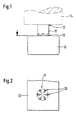
- FIG. 1 shows the spark plug electrode and the Precious metal part according to the invention before the welding process
- Figure 2 is a plan view of the profiled side of the Precious metal particle
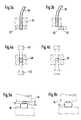
- Figures 3a, 3b, 4a, 4b, 5a and 5b the individual process steps for producing the profiled precious metal part and its welding the spark plug electrode.
- FIG. 1 shows a spark plug electrode 10 in section and a precious metal part 11, which on the front side of the Spark plug electrode 10 is attached.
- This precious metal part 11 has a smooth end face 12 and a profiled Front 13 on.
- the precious metal part 11 is so arranged that it with its profiled side 13 on the Spark plug electrode 10 rests.
- On the Spark plug electrode 10 opposite side with smoother Surface 12 of the precious metal 11 is schematically the Welding electrode 14 shown.
- FIG. 2 To clarify the design of the profiled surface 13 of the precious metal 11 should be used Figure 2.
- the Profiling of the precious metal particle 11 is designed that between the spark plug electrode 10 and the Precious metal part 11, the contact surface 20 on the outer edge of the Precious metal particle 11 are located.
- a star-shaped profile was chosen here, the ensures that only the outer areas first with the Spark plug electrode 10 form a contact surface 20.
- a precious metal wire 30 is, for example Platinum wire so guided by a holding part 31 that the Precious metal wire 30 on the other hand checked out this holder 31 protrudes. About a setting or too Preselection of the protrusion of the precious metal part can be the length of the precious metal part can be determined.
- a shearing tool 32 is now the section of Precious metal wire 30 sheared out of the holding part 31st protrudes.
- FIG. 3b shows the noble metal wire 30 a precious metal cutling 40 has already been sheared off. This shear method can also be used for relative small wire diameter a fairly large length of the Realize precious metal cutling 40.
- the ratio of Length to diameter of the precious metal hemlock is advantageously greater than 1.
- the precious metal cutling 40 is not in one embossing tool between two stamps 41 and 42 arranged and is used to enlarge the diameter or reduction in length compressed.
- this setting process is a first die 41 with a smooth surface and a second stamp 42 with a profiled Surface provided.
- the precious metal cutling 40 will due to this arrangement during the in Figure 4b the setting process shown in the figure 1 explained shape, i.e. a surface has one smooth or flat shape and the opposite Surface of the precious metal part 11 has a profiled Surface.
- the noble metal part 11 thus shaped is now, as in FIG. 5a shown on the spark plug electrode 10 for example put a center electrode in such a way that the side with the smooth surface 12 of the welding electrode 14 opposite. This is between the one to be welded Precious metal part 11 and the welding electrode 14 a good one Given contact area with low contact resistance.
- the profiled end face 13 of the precious metal part 11 is the Spark plug electrode arranged opposite, so that between the spark plug electrode and the precious metal part 11 for the welding process advantageous high contact resistance given is.
- the welding process itself is preferably carried out two-stage, with the profile tips in a first stage the contact surfaces 20 with a relatively low current be welded. This will make it even Starting conditions created for the second welding stage. In the second welding stage, the precious metal is coated with a higher current strength up to the full-surface connection with the Welded electrode.
- connection is spark plug electrode 10 and Precious metal part 11 shown after the welding process.
- This welded bond can now be further Processing stages are fed. That's the way it is for example conceivable when used as Center electrode this composite in its edge area bevel to ensure that the precious metal particle furthest to the opposite electrode of the Spark plug reaches.
- the method described allows a largely free Design of the precious metal part on the spark plug electrode.
Landscapes
- Engineering & Computer Science (AREA)
- Manufacturing & Machinery (AREA)
- Spark Plugs (AREA)
Applications Claiming Priority (3)
| Application Number | Priority Date | Filing Date | Title |
|---|---|---|---|
| DE19838538 | 1998-08-25 | ||
| DE19838538A DE19838538A1 (de) | 1998-08-25 | 1998-08-25 | Zündkerzenelektrode |
| PCT/DE1999/001072 WO2000013274A1 (de) | 1998-08-25 | 1999-04-09 | Zündkerzenelektrode |
Publications (2)
| Publication Number | Publication Date |
|---|---|
| EP1110284A1 EP1110284A1 (de) | 2001-06-27 |
| EP1110284B1 true EP1110284B1 (de) | 2004-07-07 |
Family
ID=7878618
Family Applications (1)
| Application Number | Title | Priority Date | Filing Date |
|---|---|---|---|
| EP99968269A Expired - Lifetime EP1110284B1 (de) | 1998-08-25 | 1999-04-09 | Zündkerzenelektrode |
Country Status (5)
| Country | Link |
|---|---|
| US (1) | US6630771B1 (enExample) |
| EP (1) | EP1110284B1 (enExample) |
| JP (1) | JP2002524821A (enExample) |
| DE (2) | DE19838538A1 (enExample) |
| WO (1) | WO2000013274A1 (enExample) |
Families Citing this family (10)
| Publication number | Priority date | Publication date | Assignee | Title |
|---|---|---|---|---|
| DE10230269B3 (de) * | 2002-07-05 | 2004-02-12 | Robert Bosch Gmbh | Zündkerze |
| US7049733B2 (en) * | 2003-11-05 | 2006-05-23 | Federal-Mogul Worldwide, Inc. | Spark plug center electrode assembly |
| DE102006009790A1 (de) * | 2006-03-01 | 2007-09-06 | Beru Ag | Verfahren zum Armieren eines Endes einer Mittelelektrode einer Zündkerze |
| JP4603005B2 (ja) * | 2007-03-28 | 2010-12-22 | 日本特殊陶業株式会社 | スパークプラグの製造方法 |
| DE102010014325B4 (de) * | 2010-04-09 | 2018-07-05 | Federal-Mogul Ignition Gmbh | Verfahren zum Herstellen einer Zündkerze und dadurch hergestellte Zündkerze |
| US9041274B2 (en) * | 2013-01-31 | 2015-05-26 | Federal-Mogul Ignition Company | Spark plug having firing pad |
| JP6310497B2 (ja) * | 2016-05-10 | 2018-04-11 | 日本特殊陶業株式会社 | スパークプラグ |
| US9913359B1 (en) | 2016-08-17 | 2018-03-06 | General Electric Company | Krypton-85-free spark gap with cantilevered component |
| CN110514964B (zh) * | 2019-09-05 | 2021-10-01 | 国网内蒙古东部电力有限公司检修分公司 | 一种特高压直流输电系统接地极线路故障测距方法 |
| EP4312326A1 (de) | 2022-07-22 | 2024-01-31 | Heraeus Deutschland GmbH & Co. KG | Zündkerzenelektrode mit additiv gefertigter platingruppenmetallspitze |
Family Cites Families (4)
| Publication number | Priority date | Publication date | Assignee | Title |
|---|---|---|---|---|
| DE3727526A1 (de) | 1987-08-18 | 1989-03-02 | Bosch Gmbh Robert | Verfahren zum herstellen einer zuendkerze fuer brennkraftmaschinen |
| US5856724A (en) * | 1994-02-08 | 1999-01-05 | General Motors Corporation | High efficiency, extended life spark plug having shaped firing tips |
| US5456624A (en) * | 1994-03-17 | 1995-10-10 | Alliedsignal Inc. | Spark plug with fine wire rivet firing tips and method for its manufacture |
| US6346766B1 (en) * | 1998-05-20 | 2002-02-12 | Denso Corporation | Spark plug for internal combustion engine and method for manufacturing same |
-
1998
- 1998-08-25 DE DE19838538A patent/DE19838538A1/de not_active Withdrawn
-
1999
- 1999-04-09 DE DE59909919T patent/DE59909919D1/de not_active Expired - Lifetime
- 1999-04-09 JP JP2000568154A patent/JP2002524821A/ja active Pending
- 1999-04-09 US US09/763,510 patent/US6630771B1/en not_active Expired - Fee Related
- 1999-04-09 EP EP99968269A patent/EP1110284B1/de not_active Expired - Lifetime
- 1999-04-09 WO PCT/DE1999/001072 patent/WO2000013274A1/de not_active Ceased
Also Published As
| Publication number | Publication date |
|---|---|
| WO2000013274A1 (de) | 2000-03-09 |
| EP1110284A1 (de) | 2001-06-27 |
| JP2002524821A (ja) | 2002-08-06 |
| DE19838538A1 (de) | 2000-03-02 |
| US6630771B1 (en) | 2003-10-07 |
| DE59909919D1 (de) | 2004-08-12 |
Similar Documents
| Publication | Publication Date | Title |
|---|---|---|
| EP0859436B1 (de) | Zündkerze für eine Brennkraftmaschine | |
| EP1230720A1 (de) | Elektrode, verfahren zu deren herstellung und zündkerze mit einer derartigen elektrode | |
| EP0505368B1 (de) | Verfahren zur herstellung von elektroden für zündkerzen sowie zündkerzen-elektroden | |
| DE2446929A1 (de) | Zuendkerze | |
| DE3433683A1 (de) | Verfahren zur herstellung einer mittelelektrode fuer eine zuendkerze | |
| EP1110284B1 (de) | Zündkerzenelektrode | |
| EP3221937B1 (de) | Zündkerzenelektrode, verfahren zu deren herstellung und zündkerze | |
| AT506140A1 (de) | Zündkerze | |
| EP3694684B1 (de) | Zündkerze und verfahren zur herstellung einer zündkerze | |
| DE2238283A1 (de) | Verfahren zur herstellung von zuendkerzenmittelelektroden | |
| DE602004009769T2 (de) | Zündkerze und verfahren zu ihrer herstellung | |
| DE69205251T2 (de) | Zündkerze und sein Herstellungsverfahren. | |
| EP1356555A1 (de) | Verfahren zur herstellung einer zündkerzenelektrode | |
| DE102015113175A1 (de) | Zündkerze | |
| EP1158632B1 (de) | Mittelektrode mit Edelmetallarmierung | |
| DE3504741A1 (de) | Drahtbefestigungsanordnung | |
| WO2009059340A1 (de) | Zündkerze mit edelmetallbeschichtung | |
| DE102024100766A1 (de) | Zündkerze | |
| DE2726773C3 (de) | Verfahren zur Herstellung eines Sockels für ein Halbleiterbauelementgehäuse | |
| DE522326C (de) | Ventil fuer Verbrennungskraftmaschinen | |
| EP3669431A1 (de) | Zündkerzenelektrode sowie verfahren zur herstellung dieser zündkerzenelektrode und zündkerze mit zündkerzenelektrode | |
| DE2742172A1 (de) | Von hand betaetigbare schraube mit relativ grossem kopf wie insbesondere fluegel- bzw. raendelschraube sowie verfahren zu ihrer herstellung | |
| DE102006036440B4 (de) | Verfahren zum Aufbringen eines Stiftes auf einen Elektrodengrundkörper, Verfahren zur Herstellung einer Zündkerze sowie eine Zündkerze | |
| DE102020104953A1 (de) | Zündkerze sowie Verfahren zum Herstellen einer Zündkerze | |
| DE102004019205B4 (de) | Verfahren zur Herstellung von Mittelelektroden für Zündkerzen in Nietform und Mittelelektrode in Nietform |
Legal Events
| Date | Code | Title | Description |
|---|---|---|---|
| PUAI | Public reference made under article 153(3) epc to a published international application that has entered the european phase |
Free format text: ORIGINAL CODE: 0009012 |
|
| 17P | Request for examination filed |
Effective date: 20010326 |
|
| AK | Designated contracting states |
Kind code of ref document: A1 Designated state(s): DE FR IT |
|
| GRAP | Despatch of communication of intention to grant a patent |
Free format text: ORIGINAL CODE: EPIDOSNIGR1 |
|
| GRAS | Grant fee paid |
Free format text: ORIGINAL CODE: EPIDOSNIGR3 |
|
| GRAA | (expected) grant |
Free format text: ORIGINAL CODE: 0009210 |
|
| AK | Designated contracting states |
Kind code of ref document: B1 Designated state(s): DE FR IT |
|
| REF | Corresponds to: |
Ref document number: 59909919 Country of ref document: DE Date of ref document: 20040812 Kind code of ref document: P |
|
| ET | Fr: translation filed | ||
| PLBE | No opposition filed within time limit |
Free format text: ORIGINAL CODE: 0009261 |
|
| STAA | Information on the status of an ep patent application or granted ep patent |
Free format text: STATUS: NO OPPOSITION FILED WITHIN TIME LIMIT |
|
| 26N | No opposition filed |
Effective date: 20050408 |
|
| PGFP | Annual fee paid to national office [announced via postgrant information from national office to epo] |
Ref country code: IT Payment date: 20080426 Year of fee payment: 10 |
|
| PGFP | Annual fee paid to national office [announced via postgrant information from national office to epo] |
Ref country code: FR Payment date: 20080418 Year of fee payment: 10 |
|
| REG | Reference to a national code |
Ref country code: FR Ref legal event code: ST Effective date: 20091231 |
|
| PG25 | Lapsed in a contracting state [announced via postgrant information from national office to epo] |
Ref country code: FR Free format text: LAPSE BECAUSE OF NON-PAYMENT OF DUE FEES Effective date: 20091222 |
|
| PG25 | Lapsed in a contracting state [announced via postgrant information from national office to epo] |
Ref country code: IT Free format text: LAPSE BECAUSE OF NON-PAYMENT OF DUE FEES Effective date: 20090409 |
|
| PGFP | Annual fee paid to national office [announced via postgrant information from national office to epo] |
Ref country code: DE Payment date: 20140626 Year of fee payment: 16 |
|
| REG | Reference to a national code |
Ref country code: DE Ref legal event code: R119 Ref document number: 59909919 Country of ref document: DE |
|
| PG25 | Lapsed in a contracting state [announced via postgrant information from national office to epo] |
Ref country code: DE Free format text: LAPSE BECAUSE OF NON-PAYMENT OF DUE FEES Effective date: 20151103 |