EP1109272B1 - Kohlebürstenhalter - Google Patents
Kohlebürstenhalter Download PDFInfo
- Publication number
- EP1109272B1 EP1109272B1 EP00127330A EP00127330A EP1109272B1 EP 1109272 B1 EP1109272 B1 EP 1109272B1 EP 00127330 A EP00127330 A EP 00127330A EP 00127330 A EP00127330 A EP 00127330A EP 1109272 B1 EP1109272 B1 EP 1109272B1
- Authority
- EP
- European Patent Office
- Prior art keywords
- carbon brush
- brush holder
- conductor
- spring element
- holder
- Prior art date
- Legal status (The legal status is an assumption and is not a legal conclusion. Google has not performed a legal analysis and makes no representation as to the accuracy of the status listed.)
- Expired - Lifetime
Links
- OKTJSMMVPCPJKN-UHFFFAOYSA-N Carbon Chemical compound [C] OKTJSMMVPCPJKN-UHFFFAOYSA-N 0.000 title claims abstract description 93
- 229910052799 carbon Inorganic materials 0.000 title claims abstract description 93
- 239000004020 conductor Substances 0.000 claims abstract description 25
- 238000000034 method Methods 0.000 claims abstract description 8
- 238000005452 bending Methods 0.000 claims description 5
- 238000004904 shortening Methods 0.000 claims description 3
- 238000007493 shaping process Methods 0.000 claims description 2
- 238000003780 insertion Methods 0.000 claims 1
- 230000037431 insertion Effects 0.000 claims 1
- 239000007769 metal material Substances 0.000 claims 1
- 239000002184 metal Substances 0.000 abstract 1
- 239000003245 coal Substances 0.000 description 3
- 238000004049 embossing Methods 0.000 description 3
- 229910001369 Brass Inorganic materials 0.000 description 2
- WYTGDNHDOZPMIW-RCBQFDQVSA-N alstonine Natural products C1=CC2=C3C=CC=CC3=NC2=C2N1C[C@H]1[C@H](C)OC=C(C(=O)OC)[C@H]1C2 WYTGDNHDOZPMIW-RCBQFDQVSA-N 0.000 description 2
- 239000010951 brass Substances 0.000 description 2
- 238000006073 displacement reaction Methods 0.000 description 2
- 239000000463 material Substances 0.000 description 2
- 210000001015 abdomen Anatomy 0.000 description 1
- 238000005553 drilling Methods 0.000 description 1
- 210000003746 feather Anatomy 0.000 description 1
- 230000036316 preload Effects 0.000 description 1
- 238000003466 welding Methods 0.000 description 1
- 238000004804 winding Methods 0.000 description 1
Images
Classifications
-
- H—ELECTRICITY
- H01—ELECTRIC ELEMENTS
- H01R—ELECTRICALLY-CONDUCTIVE CONNECTIONS; STRUCTURAL ASSOCIATIONS OF A PLURALITY OF MUTUALLY-INSULATED ELECTRICAL CONNECTING ELEMENTS; COUPLING DEVICES; CURRENT COLLECTORS
- H01R39/00—Rotary current collectors, distributors or interrupters
- H01R39/02—Details for dynamo electric machines
- H01R39/38—Brush holders
- H01R39/40—Brush holders enabling brush movement within holder during current collection
Definitions
- the invention relates to a carbon brush holder made in particular from punched or bent or folded sheet material with at least one of at least one wall of the carbon brush holder formed as punched an opening in the wall forming section as z.
- mounting bracket or cable connector being in the longitudinal direction of the Carbon brush holder via a screw-like spring element which can be fixed in this acted upon carbon brush is slidably disposed, of which a conductor like a strand goes out, which is guided within the spring element, an S-shaped or serpentine course within the spring element has and preferably at the rear End of the carbon brush holder attached to this as welded.
- a carbon brush holder is known from EP 0 398 320 B1, which is considered to be the closest prior art, from the one wall of which one Section is cut out and bent outwards, on which the strand of the axially in the Carbon holder slidable carbon brush is attached. So that the strand with the on the Coal brush acting coil spring does not collide, the former is through a longitudinal slot of the coal holder led outwards.
- a carbon brush holder is known, the end with a cap is provided with a cup-shaped recess in which a portion of one of a Carbon brush outgoing strand is stackable. Between the recess and the carbon brush the strand runs straight.
- a strand penetrates through one Carbon brush runs out, an axial opening of a plug.
- the opening extends along the axis of the carbon brush.
- the present invention is based on the problem of a carbon brush holder type mentioned in the beginning so that regardless of the position of the carbon brush and thus the one extending within the helically extending spring element Conductor such as wire is ensured that this with the spring element, ie. H. whose Windings, or the carbon brush holder can not get caught.
- the problem is essentially solved in that the electrical conductor regardless of the position of the carbon brush, a direct or indirect pattern has within the spring element and that formed by the stamped course Envelope runs within the spring element.
- the conductor is like stranded wire in its or her apparent shortening predetermined course stamped.
- the conductor can be shaped, pre-tensioned, Pre-drilling, pre-bending, bending or in any other way in its movement be pre-embossed.
- the leader will follow a course within the Spring defining insert which, for. B. can be pre-embossed or biased.
- the shaping such as pre-stamping, pre-bending, preferably takes place during the Assembly process.
- the course of the conductor within the spring element can thereby be determinable that when the conductor is elongated within the spring element, the latter apparent shortening by means of a removable aid such as a spike from the opening can be kept away.
- a pin-like element such as a mandrel is used as an aid is used when pushing in the carbon brush of its end of the carbon brush holder on the inside. It can be used as an aid pin-shaped element can be used, by means of which the connection such as welding between the conductor and the carbon brush holder itself is checked.
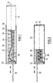
- the carbon brush 14 experiences in the direction of the front opening 16 of the Carbon holder 10 by means of a spring element 18, preferably in the form of a helical spring a force application.
- the coil spring 18 is in the region of the end face 16 opposite region 20 of the carbon holder 10 can be fixed or supported.
- a strand 22 extends from the carbon brush 14, for example by ramming or in other known manner is connected to the carbon brush 14.
- the strand 22 extends itself in the space 24 surrounded by the coil spring 18 and runs as a function of the position of the carbon brush 14 more or less S-shaped or serpentine.
- the braid is attached to a tab, for example welded.
- Known carbon holder 10 stamped and folded from sheet material such as sheet brass the opposite walls to form so-called feather bellies to the outside are arched, have cable plugs or fastening tabs or another one Outer surface of the carbon holder 10 protruding portion.
- This is in Fig. 2 with the Reference numeral 26 provided.
- the protruding section 26 is a single wall punched and bent section, so that the corresponding wall has an opening 28.
- the strand 22 becomes more actual regardless of it or apparent length enclosed by an envelope equal to or less than that Inner envelope of the coil spring 18 is.
- a mandrel 30 In order to pre-emboss the strand 22 in its course, 14 in the space 24 surrounded by the helical spring 18 is an auxiliary element designed as a mandrel 30 introduced, which extends up to the end face 32 of the carbon brush on the inside of the carbon holder 14 extends. Furthermore, the mandrel 30 extends between the strand 22 and the opening 28. If the carbon brush 14 is now pressed into the carbon holder 10, the mandrel 30 causes when pushing the carbon brush into the carbon holder 10 moves, that is moved outwards the strand 22 is kept away from the opening 28, i. H.
- the strand 22 experiences by means of the dome 30 when the Carbon brush 14 in the carbon holder 10 an embossing or pre-bending such that the strand 22 can no longer get caught with the coil spring 18 in the region of the opening 28. On Jamming the strand 22 between the spring 18 and the opening 28 is thus no longer possible.
- the mandrel 30 itself can perform a double function. On the one hand, the mandrel 30 can Ensure the desired knockout of the strand 22. On the other hand, the mandrel 30 can Check the connection such as welded connection between the strand 22 and the carbon holder 10 are used in the rear end region 20.
- a course specification for the strand 22 can also be achieved, for example, by providing the strand 22 with an insert, which has the desired preload or knockout.
Landscapes
- Motor Or Generator Current Collectors (AREA)
- Pens And Brushes (AREA)
Description
- Anordnen der Kohlebürste in dem Kohlebürstenhalter in einer aus dem Kohlehalter herausgedrückten oder weitgehend herausgedrückten Stellung, wobei der Leiter in gestreckter oder weitgehend gestreckter Lage durch den von dem Federelement umgebenen Raum geführt ist,
- Einführen eines Hilfsmittels zwischen den Leiter und das Federelement, wobei das Hilfsmittel sich entlang der Aussparung erstreckt, und
- Hineindrücken der Kohlebürste in den Kohlehalter bei gleichzeitigem Mitbewegen des Hilfsmittels.
- Fig. 1
- einen Kohlehalter mit aus diesem herausgedrückter Kohlebürste und
- Fig. 2
- ein der Fig. 1 entsprechender Kohlehalter mit hineingedrückter Kohlebürste.
Claims (8)
- Kohlebürstenhalter (10) aus insbesondere gestanztem bzw. gefaltetem Blechmaterial mit zumindest einem aus zumindest einer Wandung des Kohlebürstenhalters ausgebildeten wie ausgestanzten eine Öffnung (28) in der Wandung bildenden Abschnitt als zum Beispiel Befestigungslasche oder Kabelstecker, wobei in Längsrichtung (12) des Kohlebürstenhalters eine über ein in diesem festlegbares schraubenartiges Federelement (18) beaufschlagte Kohlebürste (14) verschiebbar angeordnet ist, von der ein Leiter wie eine Litze (22) ausgeht, der bzw. die innerhalb des Federelementes geführt ist, eine S- oder schlangenförmigen Verlauf innerhalb des Federelements aufweist und vorzugsweise am hinteren Endbereich (20) des Kohlebürstenhalters mit diesem befestigt wie verschweißt ist,
dadurch gekennzeichnet, dass der elektrische Leiter kohlebürstenpositionsunabhängig einen aufgeprägten Verlauf innerhalb des Federelementes (18) derart aufweist, dass die von dem Verlauf gebildete Umhüllende innerhalb des Federelementes verläuft. - Kohlebürstenhalter nach Anspruch 1,
dadurch gekennzeichnet, dass der Leiter durch Formgebung, Vorspannung, Vordrillung, Vorknicken oder Vorbiegen in seinem Bewegungsverlauf vorgeprägt ist. - Kohlebürstenhalter nach Anspruch 1,
dadurch gekennzeichnet, dass der Leiter eine dessen Verlauf innerhalb des von dem Federelement (18) umgebenen Raums (24) vorgebende Einlage aufweist.. - Kohlebürstenhalter nach Anspruch 3,
dadurch gekennzeichnet, dass die Einlage vorgeprägt bzw. vorgespannt ist. - Kohlebürstenhalter nach zumindest Anspruch 1,
dadurch gekennzeichnet, dass der Leiter in seinem Verlauf innerhalb des Federelementes (18) dadurch einprägbar ist, dass bei innerhalb des Federelementes langgestreckt oder im Wesentlichen langgestreckt verlaufendem Leiter dieser beim scheinbaren Verkürzen mittels eines Hilfselementes (30) wie Dom von der Öffnung (28) fernhaltbar ist. - Verfahren zum Bestücken eines Kohlebürstenhalters (10) nach einem der Ansprüche 1-5 mit in dessen Längsrichtung verschiebbarer von einem in dem Kohlebürstenhalter festleg- bzw. abstützbarem Federelement (18) beaufschlagter Kohlebürste (14), von der ein Leiter wie eine Litze (22) ausgeht, die in von dem Federelement umgebenen Raum S- oder schlangenförmig verläuft, wobei in zumindest einer Wandung des Kohlebürstenhalters eine Aussparung (28) vorhanden ist, gekennzeichnet durch die Verfahrensschritte:wobei das Hilfselement sich entlang der Aussparung (28) erstreckt, undAnordnen der Kohlebürste (14) in dem Kohlebürstenhalter (10) in einer aus dem Kohlebürstenhalter herausgedrückten oder weitgehend herausgedrückten Stellung und Führen des Leiters in gestreckter oder weitgehend gestreckter Lage durch den von dem Federelement (18) umgebenen Raum und Verbinden des Leiters mit dem Kohlebürstenhalter in dessen hinterem Endbereich,Einführen eines Hilfselementes (30) zwischen den Leiter und das Federelement,Hineindrücken der Kohlebürste in den Kohlebürstenhalter bei gleichzeitigem Mitbewegen des Hilfselementes..
- Verfahren nach Anspruch 6,
dadurch gekennzeichnet, dass ein entfernbares stiftartiges Element wie Dom als das Hilfselement (30) benutzt wird, das bzw. der von der kohlehalterinnenseitig verlaufenden Stirnfläche der Kohlebürste (14) ausgeht. - Verfahren nach Anspruch 6 oder 7,
dadurch gekennzeichnet, dass mittels des stiftförmigen Elementes (30) die Verbindung wie Verschweißung zwischen dem Leiter und dem Kohlebürstenhalter (10) überprüft wird.
Applications Claiming Priority (2)
| Application Number | Priority Date | Filing Date | Title |
|---|---|---|---|
| DE19960689A DE19960689A1 (de) | 1999-12-15 | 1999-12-15 | Kohlebürstenhalter |
| DE19960689 | 1999-12-15 |
Publications (3)
| Publication Number | Publication Date |
|---|---|
| EP1109272A2 EP1109272A2 (de) | 2001-06-20 |
| EP1109272A3 EP1109272A3 (de) | 2002-02-06 |
| EP1109272B1 true EP1109272B1 (de) | 2004-03-10 |
Family
ID=7932879
Family Applications (1)
| Application Number | Title | Priority Date | Filing Date |
|---|---|---|---|
| EP00127330A Expired - Lifetime EP1109272B1 (de) | 1999-12-15 | 2000-12-13 | Kohlebürstenhalter |
Country Status (3)
| Country | Link |
|---|---|
| EP (1) | EP1109272B1 (de) |
| AT (1) | ATE261618T1 (de) |
| DE (2) | DE19960689A1 (de) |
Families Citing this family (2)
| Publication number | Priority date | Publication date | Assignee | Title |
|---|---|---|---|---|
| JP3908096B2 (ja) | 2002-06-12 | 2007-04-25 | 三菱電機株式会社 | 回転電機 |
| US9515443B2 (en) | 2010-06-08 | 2016-12-06 | Single Buoy Moorings Inc. | Brush holder for an electrical swivel |
Family Cites Families (6)
| Publication number | Priority date | Publication date | Assignee | Title |
|---|---|---|---|---|
| US2254277A (en) * | 1940-05-29 | 1941-09-02 | Ohio Carbon Company | Electric contact brush |
| DE1156497B (de) * | 1961-09-26 | 1963-10-31 | Licentia Gmbh | Verschlusssicherung fuer Buerstenhalter mit Verschlussschraube fuer elektrische Geraete |
| DE7720448U1 (de) * | 1977-06-29 | 1979-02-15 | Siemens Ag, 1000 Berlin Und 8000 Muenchen | Rohrbürstenhalter |
| DE8906152U1 (de) * | 1989-05-18 | 1989-11-16 | Schunk Motorensysteme GmbH, 2875 Ganderkesee | Kohlehalter |
| DE4141307C2 (de) * | 1991-12-14 | 1999-02-18 | Fhp Motors Gmbh | Bürstenführungsanordnung für eine elektrische Maschine |
| US5631513A (en) * | 1995-03-20 | 1997-05-20 | Ametek, Inc. | Dynamoelectric brush holder clip and connector |
-
1999
- 1999-12-15 DE DE19960689A patent/DE19960689A1/de not_active Ceased
-
2000
- 2000-12-13 DE DE50005588T patent/DE50005588D1/de not_active Expired - Lifetime
- 2000-12-13 AT AT00127330T patent/ATE261618T1/de not_active IP Right Cessation
- 2000-12-13 EP EP00127330A patent/EP1109272B1/de not_active Expired - Lifetime
Also Published As
| Publication number | Publication date |
|---|---|
| DE19960689A1 (de) | 2001-07-05 |
| ATE261618T1 (de) | 2004-03-15 |
| EP1109272A2 (de) | 2001-06-20 |
| DE50005588D1 (de) | 2004-04-15 |
| EP1109272A3 (de) | 2002-02-06 |
Similar Documents
| Publication | Publication Date | Title |
|---|---|---|
| DE19824808C1 (de) | Halterung für längliche Körper mit elektrischer Abschirmung | |
| DE10128395B4 (de) | Spulenkörper für Transformator bzw. Stromwandler | |
| DE2711723A1 (de) | Verfahren zum anschliessen eines feinen drahtes und verbinder zur durchfuehrung dieses verfahrens | |
| EP1133013B1 (de) | Kontaktstück für eine elektrische Steckverbindung sowie Verfahren zu dessen Herstellung | |
| DE4322758A1 (de) | Elektrischer Buchsenkontakt zum Einsetzen in ein Buchsengehäuse | |
| DE112014004195T5 (de) | Anschluss, Verbindungsstrukturkörper, und Verfahren zur Herstellung des Anschlusses | |
| EP0968548A1 (de) | Steckerbuchse mit in der form eines hyperboloids angeordneten kontaktbereichen | |
| DE102010052627A1 (de) | Mantelleitungscrimpverbindung für Zug- und Druckentlastung einschließlich Schirmübertragung zur Metallhülse | |
| DE4320539C2 (de) | Leitungsdraht-Verbindungsklemme | |
| DE2742967A1 (de) | Federklammer fuer eine rohrfoermige elektrische sicherung | |
| EP2006963B1 (de) | Befestigungsverfahren für einen Kabelschuh und Kabelbiegevorrichtung | |
| EP1109272A2 (de) | Kohlebürstenhalter | |
| DE2936616C2 (de) | Verbinder für zwei Koaxialkabelenden | |
| DE69403652T2 (de) | Spleissleiste fuer isolierte telekommunikationskabel | |
| DE102008019971B3 (de) | Leitersteckverbinder | |
| DE10227235A1 (de) | Leiteranschluss | |
| DE2509101C3 (de) | Elektrischer Rohrheizkörper mit flachovalem Querschnitt | |
| EP4210174B1 (de) | Verbesserte leitfähige hülse und verfahren zum verbinden eines leiterabschnitts mit der leitfähigen hülse | |
| DE10124532A1 (de) | Elektrische Steckverbindung | |
| EP0704932A2 (de) | Steckklemme | |
| DE102020104417A1 (de) | Anschlussklemme | |
| DE1044204B (de) | Steckerbuchse, insbesondere fuer die Mess- und Nachrichtentechnik | |
| DE3627529A1 (de) | Halter fuer eine schleifkohle | |
| EP0182736A2 (de) | Kuppelkontaktstück zum Verbinden runder elektrischer Leiter | |
| EP3560039B1 (de) | Leiterverbindung und verfahren zur herstellung einer leiterverbindung |
Legal Events
| Date | Code | Title | Description |
|---|---|---|---|
| PUAI | Public reference made under article 153(3) epc to a published international application that has entered the european phase |
Free format text: ORIGINAL CODE: 0009012 |
|
| AK | Designated contracting states |
Kind code of ref document: A2 Designated state(s): AT BE CH CY DE DK ES FI FR GB GR IE IT LI LU MC NL PT SE TR |
|
| AX | Request for extension of the european patent |
Free format text: AL;LT;LV;MK;RO;SI |
|
| PUAL | Search report despatched |
Free format text: ORIGINAL CODE: 0009013 |
|
| AK | Designated contracting states |
Kind code of ref document: A3 Designated state(s): AT BE CH CY DE DK ES FI FR GB GR IE IT LI LU MC NL PT SE TR |
|
| AX | Request for extension of the european patent |
Free format text: AL;LT;LV;MK;RO;SI |
|
| 17P | Request for examination filed |
Effective date: 20020620 |
|
| AKX | Designation fees paid |
Free format text: AT BE CH CY DE DK ES FI FR GB GR IE IT LI LU MC NL PT SE TR |
|
| AXX | Extension fees paid |
Free format text: RO PAYMENT 20020620;SI PAYMENT 20020620 |
|
| 17Q | First examination report despatched |
Effective date: 20021015 |
|
| REG | Reference to a national code |
Ref country code: GB Ref legal event code: FG4D Free format text: NOT ENGLISH |
|
| GRAP | Despatch of communication of intention to grant a patent |
Free format text: ORIGINAL CODE: EPIDOSNIGR1 |
|
| GRAS | Grant fee paid |
Free format text: ORIGINAL CODE: EPIDOSNIGR3 |
|
| GRAA | (expected) grant |
Free format text: ORIGINAL CODE: 0009210 |
|
| AK | Designated contracting states |
Kind code of ref document: B1 Designated state(s): AT BE CH CY DE DK ES FI FR GB GR IE IT LI LU MC NL PT SE TR |
|
| AX | Request for extension of the european patent |
Extension state: RO SI |
|
| PG25 | Lapsed in a contracting state [announced via postgrant information from national office to epo] |
Ref country code: GB Free format text: LAPSE BECAUSE OF FAILURE TO SUBMIT A TRANSLATION OF THE DESCRIPTION OR TO PAY THE FEE WITHIN THE PRESCRIBED TIME-LIMIT Effective date: 20040310 Ref country code: TR Free format text: LAPSE BECAUSE OF FAILURE TO SUBMIT A TRANSLATION OF THE DESCRIPTION OR TO PAY THE FEE WITHIN THE PRESCRIBED TIME-LIMIT Effective date: 20040310 Ref country code: FR Free format text: LAPSE BECAUSE OF FAILURE TO SUBMIT A TRANSLATION OF THE DESCRIPTION OR TO PAY THE FEE WITHIN THE PRESCRIBED TIME-LIMIT Effective date: 20040310 Ref country code: NL Free format text: LAPSE BECAUSE OF FAILURE TO SUBMIT A TRANSLATION OF THE DESCRIPTION OR TO PAY THE FEE WITHIN THE PRESCRIBED TIME-LIMIT Effective date: 20040310 Ref country code: IE Free format text: LAPSE BECAUSE OF FAILURE TO SUBMIT A TRANSLATION OF THE DESCRIPTION OR TO PAY THE FEE WITHIN THE PRESCRIBED TIME-LIMIT Effective date: 20040310 Ref country code: FI Free format text: LAPSE BECAUSE OF FAILURE TO SUBMIT A TRANSLATION OF THE DESCRIPTION OR TO PAY THE FEE WITHIN THE PRESCRIBED TIME-LIMIT Effective date: 20040310 Ref country code: CY Free format text: LAPSE BECAUSE OF FAILURE TO SUBMIT A TRANSLATION OF THE DESCRIPTION OR TO PAY THE FEE WITHIN THE PRESCRIBED TIME-LIMIT Effective date: 20040310 |
|
| REG | Reference to a national code |
Ref country code: CH Ref legal event code: EP |
|
| REG | Reference to a national code |
Ref country code: IE Ref legal event code: FG4D Free format text: GERMAN |
|
| REF | Corresponds to: |
Ref document number: 50005588 Country of ref document: DE Date of ref document: 20040415 Kind code of ref document: P |
|
| PG25 | Lapsed in a contracting state [announced via postgrant information from national office to epo] |
Ref country code: DK Free format text: LAPSE BECAUSE OF FAILURE TO SUBMIT A TRANSLATION OF THE DESCRIPTION OR TO PAY THE FEE WITHIN THE PRESCRIBED TIME-LIMIT Effective date: 20040610 Ref country code: GR Free format text: LAPSE BECAUSE OF FAILURE TO SUBMIT A TRANSLATION OF THE DESCRIPTION OR TO PAY THE FEE WITHIN THE PRESCRIBED TIME-LIMIT Effective date: 20040610 Ref country code: SE Free format text: LAPSE BECAUSE OF FAILURE TO SUBMIT A TRANSLATION OF THE DESCRIPTION OR TO PAY THE FEE WITHIN THE PRESCRIBED TIME-LIMIT Effective date: 20040610 |
|
| PG25 | Lapsed in a contracting state [announced via postgrant information from national office to epo] |
Ref country code: ES Free format text: LAPSE BECAUSE OF FAILURE TO SUBMIT A TRANSLATION OF THE DESCRIPTION OR TO PAY THE FEE WITHIN THE PRESCRIBED TIME-LIMIT Effective date: 20040621 |
|
| NLV1 | Nl: lapsed or annulled due to failure to fulfill the requirements of art. 29p and 29m of the patents act | ||
| GBV | Gb: ep patent (uk) treated as always having been void in accordance with gb section 77(7)/1977 [no translation filed] |
Effective date: 20040310 |
|
| REG | Reference to a national code |
Ref country code: IE Ref legal event code: FD4D |
|
| PG25 | Lapsed in a contracting state [announced via postgrant information from national office to epo] |
Ref country code: LU Free format text: LAPSE BECAUSE OF NON-PAYMENT OF DUE FEES Effective date: 20041213 Ref country code: AT Free format text: LAPSE BECAUSE OF NON-PAYMENT OF DUE FEES Effective date: 20041213 |
|
| PG25 | Lapsed in a contracting state [announced via postgrant information from national office to epo] |
Ref country code: LI Free format text: LAPSE BECAUSE OF NON-PAYMENT OF DUE FEES Effective date: 20041231 Ref country code: BE Free format text: LAPSE BECAUSE OF NON-PAYMENT OF DUE FEES Effective date: 20041231 Ref country code: MC Free format text: LAPSE BECAUSE OF NON-PAYMENT OF DUE FEES Effective date: 20041231 Ref country code: CH Free format text: LAPSE BECAUSE OF NON-PAYMENT OF DUE FEES Effective date: 20041231 |
|
| PLBE | No opposition filed within time limit |
Free format text: ORIGINAL CODE: 0009261 |
|
| STAA | Information on the status of an ep patent application or granted ep patent |
Free format text: STATUS: NO OPPOSITION FILED WITHIN TIME LIMIT |
|
| EN | Fr: translation not filed | ||
| 26N | No opposition filed |
Effective date: 20041213 |
|
| BERE | Be: lapsed |
Owner name: *SCHUNK ITALIA S.R.L. Effective date: 20041231 |
|
| REG | Reference to a national code |
Ref country code: CH Ref legal event code: PL |
|
| BERE | Be: lapsed |
Owner name: *SCHUNK ITALIA S.R.L. Effective date: 20041231 |
|
| PG25 | Lapsed in a contracting state [announced via postgrant information from national office to epo] |
Ref country code: PT Free format text: LAPSE BECAUSE OF NON-PAYMENT OF DUE FEES Effective date: 20040810 |
|
| PGFP | Annual fee paid to national office [announced via postgrant information from national office to epo] |
Ref country code: IT Payment date: 20101217 Year of fee payment: 11 |
|
| PGFP | Annual fee paid to national office [announced via postgrant information from national office to epo] |
Ref country code: DE Payment date: 20101214 Year of fee payment: 11 |
|
| REG | Reference to a national code |
Ref country code: DE Ref legal event code: R119 Ref document number: 50005588 Country of ref document: DE Effective date: 20130702 |
|
| PG25 | Lapsed in a contracting state [announced via postgrant information from national office to epo] |
Ref country code: DE Free format text: LAPSE BECAUSE OF NON-PAYMENT OF DUE FEES Effective date: 20130702 |
|
| PG25 | Lapsed in a contracting state [announced via postgrant information from national office to epo] |
Ref country code: IT Free format text: LAPSE BECAUSE OF NON-PAYMENT OF DUE FEES Effective date: 20121213 |