EP1108392B1 - Methods and apparatus for non-uniform temporal cardiac imaging - Google Patents
Methods and apparatus for non-uniform temporal cardiac imaging Download PDFInfo
- Publication number
- EP1108392B1 EP1108392B1 EP00311150A EP00311150A EP1108392B1 EP 1108392 B1 EP1108392 B1 EP 1108392B1 EP 00311150 A EP00311150 A EP 00311150A EP 00311150 A EP00311150 A EP 00311150A EP 1108392 B1 EP1108392 B1 EP 1108392B1
- Authority
- EP
- European Patent Office
- Prior art keywords
- heart
- patient
- accordance
- phases
- phase
- Prior art date
- Legal status (The legal status is an assumption and is not a legal conclusion. Google has not performed a legal analysis and makes no representation as to the accuracy of the status listed.)
- Expired - Lifetime
Links
- 230000000747 cardiac effect Effects 0.000 title claims description 50
- 230000002123 temporal effect Effects 0.000 title claims description 23
- 238000003384 imaging method Methods 0.000 title claims description 16
- 238000000034 method Methods 0.000 title claims description 16
- 238000013170 computed tomography imaging Methods 0.000 claims description 11
- 230000005855 radiation Effects 0.000 claims description 3
- 238000002591 computed tomography Methods 0.000 description 13
- 230000007704 transition Effects 0.000 description 7
- 230000008859 change Effects 0.000 description 4
- 238000005259 measurement Methods 0.000 description 4
- 230000007246 mechanism Effects 0.000 description 3
- 230000002238 attenuated effect Effects 0.000 description 2
- 230000008569 process Effects 0.000 description 2
- 238000005070 sampling Methods 0.000 description 2
- 238000004458 analytical method Methods 0.000 description 1
- 230000005540 biological transmission Effects 0.000 description 1
- 230000001419 dependent effect Effects 0.000 description 1
- 238000010586 diagram Methods 0.000 description 1
- 238000001914 filtration Methods 0.000 description 1
- 230000001771 impaired effect Effects 0.000 description 1
- 238000011179 visual inspection Methods 0.000 description 1
Images
Classifications
-
- A—HUMAN NECESSITIES
- A61—MEDICAL OR VETERINARY SCIENCE; HYGIENE
- A61B—DIAGNOSIS; SURGERY; IDENTIFICATION
- A61B6/00—Apparatus or devices for radiation diagnosis; Apparatus or devices for radiation diagnosis combined with radiation therapy equipment
- A61B6/54—Control of apparatus or devices for radiation diagnosis
- A61B6/541—Control of apparatus or devices for radiation diagnosis involving acquisition triggered by a physiological signal
Definitions
- This invention relates generally to methods and apparatus for computed tomography cardiac imaging, and more particularly to methods and apparatus for non-uniform temporal recording of cardiac images.
- an x-ray source projects a fan-shaped beam which is collimated to lie within an X-Y plane of a Cartesian coordinate system and generally referred to as the "imaging plane".
- the x-ray beam passes through the object being imaged, such as a patient.
- the beam after being attenuated by the object, impinges upon an array of radiation detectors.
- the intensity of the attenuated beam radiation received at the detector array is dependent upon the attenuation of the x-ray beam by the object.
- Each detector element of the array produces a separate electrical signal that is a measurement of the beam attenuation at the detector location.
- the attenuation measurements from all the detectors are acquired separately to produce a transmission profile.
- the x-ray source and the detector array are rotated with a gantry within the imaging plane and around the object to be imaged so that the angle at which the x-ray beam intersects the object constantly changes.
- a group of x-ray attenuation measurements, i.e., projection data, from the detector array at one gantry angle is referred to as a "view”.
- a "scan" of the object comprises a set of views made at different gantry angles, or view angles, during one revolution of the x-ray source and detector.
- the projection data is processed to construct an image that corresponds to a two dimensional slice taken through the object.
- CT numbers integers called "CT numbers” or “Hounsfield units”, which are used to control the brightness of a corresponding pixel on a cathode ray tube display.
- Computed tomography images of the heart are useful for a number of diagnostic and surgical purposes. At least one known procedure requires that a collection of cardiac phase images be obtained. However, the process of obtaining such a collection is complicated by the fact that the heart does not beat in a uniform temporal fashion. During a single cardiac cycle, there are some times during which the volume of the heart is changing faster than average, and some times during which the volume changes more slowly than average.
- images corresponding to several phases of a cardiac cycle are captured at evenly spaced intervals. The images that are acquired are evenly spaced in time, resulting in an oversampling of certain phases of the cardiac cycle. Other phases are undersampled. Thus, temporal resolution is impaired. It would therefore be desirable for CT imaging apparatus and methods to optimize a collection of cardiac phase images by avoiding over- and undersampling.
- the invention provides, in one embodiment, a method for imaging a heart of a patient utilizing a CT imaging system including steps of assigning a scanning priority to phases of a representative cardiac cycle of the patient's heart, selecting phases of the cardiac cycle for scanning in accordance with the assigned scanning priority, and obtaining image slices of the patient's heart corresponding to the selected phases of the cardiac cycle.
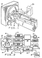
- a computed tomograph (CT) imaging system 10 is shown as including a gantry 12 representative of a "third generation" CT scanner.
- Gantry 12 has an x-ray source 14 that projects a beam of x-rays 16 toward a detector array 18 on the opposite side of gantry 12.
- Detector array 18 is formed by detector elements 20 which together sense the projected x-rays that pass through an object 22, for example a medical patient.
- Detector array 18 may be fabricated in a single slice or multi-slice configuration.
- Each detector element 20 produces an electrical signal that represents the intensity of an impinging x-ray beam and hence the attenuation of the beam as it passes through patient 22.
- gantry 12 and the components mounted thereon rotate about a center of rotation 24.
- Control mechanism 26 includes an x-ray controller 28 that provides power and timing signals to x-ray source 14 and a gantry motor controller 30 that controls the rotational speed and position of gantry 12.
- a data acquisition system (DAS) 32 in control mechanism 26 samples analog data from detector elements 20 and converts the data to digital signals for subsequent processing.
- An image reconstructor 34 receives sampled and digitized x-ray data from DAS 32 and performs high speed image reconstruction. The reconstructed image is applied as an input to a computer 36 which stores the image in a mass storage device 38.
- DAS data acquisition system
- Computer 36 also receives commands and scanning parameters from an operator via console 40 that has a keyboard.
- An associated cathode ray tube display 42 allows the operator to observe the reconstructed image and other data from computer 36.
- the operator supplied commands and parameters are used by computer 36 to provide control signals and information to DAS 32, x-ray controller 28 and gantry motor controller 30.
- computer 36 operates a table motor controller 44 which controls a motorized table 46 to position patient 22 in gantry 12. Particularly, table 46 moves portions of patient 22 through gantry opening 48 in a z-axis direction.
- a non-uniform sampling technique is used to optimize temporal resolution of a collection of cardiac phase images.
- Sampling points are determined utilizing a signal representative of volumetric change of the heart, such as an EKG signal from EKG machine 50.
- data representing a typical cardiac cycle 52 of the heart of patient 22 is obtained utilizing EKG machine 50.
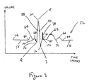
- a representative cardiac cycle 52 is computed from EKG signal data obtained from a plurality of normal cardiac cycles. The plurality of cycles are averaged to obtain the representative normal cycle, such as that illustrated in Figure 3.
- the representative cycle is analyzed for changes that occur at each phase in cardiac cycle 52.
- flat or baseline sections 54, 56, 58 are identified, as are local maxima 60, 62, 64, 66, 68 and minima 70, 72, 74, 76.
- Times at which local maxima 60, 62, 64, 66, 68 and minima 70, 72, 74, 76 occur relative to a reference time in cardiac cycle 52 are obtained by utilizing second derivative information from cardiac waveform 52.
- Voltages representing volume changes of the heart of patient 22 are produced by EKG machine 50.
- EKG cycle 52 thus determined represents volume changes of the heart.
- Rankings are assigned based upon a distance at each local maxima and minima from a baseline section 54, 55, 58 of waveform 52.
- data of representative cardiac cycle waveform 52 is filtered to reduce temporal and spatial noise.
- cardiac cycle 52 is analyzed to determine volume changes and rates of change. Based on these determinations, a threshold is applied to cardiac waveform 52 to eliminate changes in the waveform that are small enough to be ignored.
- the threshold is selected by computing an estimated noise level or by estimating a noise level by visual inspection of waveform 52. Small volume changes in waveform 52 below the threshold are replaced with a flat baseline. For example, points 68, 74, and 76 are ignored.
- Short temporal impulses 78 such as those having shorter duration than a temporal resolution of CT imaging device 10, also are ignored. For example, impulses of duration less than about 100ms are ignored.
- thresholds are selected in accordance with a maximum desired temporal and spatial resolution. In one embodiment, thresholding is performed prior to locating maxima and minima of cardiac waveform 52.
- each point 60, 62, 64, 66, 70, 72, 74 corresponds to different phases of representative cardiac cycle 52 of patient 22.
- Priority values are assigned to the phases of each of the local maxima 60, 62, 64, 66 and minima 70, 72, 74 in accordance with volume differences from baseline 54, 56, 58, the volume distances being represented by vertical distances in cardiac waveform 52. In one embodiment, greater volume differences are assigned greater priority.
- One such ordering of priority, in order from highest to lowest, is 60, 70, 62, 72, 64, and 66.
- At least one transition point 78, 80, 82, 84 or 86 on baseline 54, 56, 58 is also selected for scanning and imaging.
- Transition points 78, 80, 82, 84, and 86 occur at phases in which a volume change just begins to occur after a period of little or no motion. However, it is only necessary to scan at a single transition point, e.g., point 78, because the heart volume of patient 22 is approximately the same at each transition point 78, 80, 82, 84, and 86.
- a single imaging scan at the selected transition point is used to represent the heart at each of transition points 78, 80, 82, 84, 86.
- a transition point is given a high priority above that of all maxima and minima.
- additional phases are assigned scanning priorities in accordance with temporal and spatial gradients. For example, phases 88 and 90 are selected between minima and maxima 72 and 60, and 60 and 70, respectively. Phases 88 and 90 or other such additional phases are selected when doing so is determined to be advantageous for reconstruction of images. Priority values are then assigned to the selected additional phases 88, 90. When there are fewer minima and maxima than phases, all minima and maxima phases are selected. Also, additional phases such as 88 and 90 are selected in order of priority (for example, those at which a magnitude of the slope of waveform 52 is greatest) until a total of the selected phases is equal to the number of sectors.
- minima and maxima points are selected, up to a maximum number of available sectors. For example, only those minima and maxima having the greatest volume change as indicated by a vertical distance from baseline 54, 56, 58 are selected for scanning. More generally, phases are sorted in accordance with their assigned priority, and a number of points N of highest priority are selected, where N is a number of phases desired for generating images.
- a cine cardiac scan (i.e., a scan during which gantry 12 rotates, but table 46 is held stationary) is then performed by CT imaging system 10 at a time interval corresponding to each of the N points along waveform 52.
- a reference phase from an EKG machine 50 sensing cardiac cycles of patient 22 is used, in one embodiment, to establish a reference for scanning times. For example, scanning times are referenced to occurrences of R peaks sensed by CT imaging system 10 in an EKG signal received from EKG machine 50.
- An axial image slice is generated for each phase of a cine scan when CT imaging system 10 is a single-slice imaging system.
- the cine scanning step is repeated for each plane or slice after table 46 is stepped to a new location. Collection of phases for more than one image plane or slice is further facilitated, in one embodiment, by utilizing a multi-slice imaging system as CT imaging system 10. Suitable adjustments are made in the stepping distance of table 46 in accordance with slice thicknesses and a number of slices collected simultaneously during a scan.
- N phases are not sufficient to include a desired temporal midpoint or phase, such as 88, during acquisition.
- linear interpolations between phases preceding and following midpoint 88 are performed to fill in a temporal coverage gap in coverage.
- the newly interpolated slice is considered an additional phase for purposes of the invention.
- a "frame” consists of a single scanned image.
- a "frame” is a collection comprising a plurality of such images representing different image slices or planes.
- each image in the collection corresponds to the same phase in the patient's cardiac cycle.
- an animated display representing the heart of patient 22 is produced from an optimized collection of cardiac phase images.
- the resulting animated images have improved temporal resolution.
- CT imaging system 10 is programmed to perform steps described above.
- computer 36 receives an EKG signal from EKG machine 50 for analysis.
- Software or firmware operating computer 36 averages an EKG waveform over a plurality of cycles and assigns scanning priorities in accordance with measurable characteristics of the average waveform.
- software operating computer 36 assigns priorities strictly in accordance with computed second derivative values of a cardiac waveform to recognize maxima and minima, and also locates maximum and minimum slopes of the cardiac waveform.
- a baseline phase is also selected for scanning. Scanning is performed automatically by gating scan cycles with observed R-peaks of a cardiac cycle from an EKG taken during scanning.
- Image reconstructor 34 and/or computer 36 then compute images for display on CRT 42.
- CT cardiac images having improved temporal resolution are obtained by avoiding oversampling and undersampling of cardiac phases.
- CT system described herein is a "third generation” system in which both the x-ray source and detector rotate with the gantry.
- CT systems including "fourth generation” systems wherein the detector is a full-ring stationary detector and only the x-ray source rotates with the gantry, may be used if individual detector elements are corrected to provide substantially uniform responses to a given x-ray beam.
Landscapes
- Health & Medical Sciences (AREA)
- Life Sciences & Earth Sciences (AREA)
- Engineering & Computer Science (AREA)
- Medical Informatics (AREA)
- Pathology (AREA)
- Heart & Thoracic Surgery (AREA)
- High Energy & Nuclear Physics (AREA)
- Physics & Mathematics (AREA)
- Nuclear Medicine, Radiotherapy & Molecular Imaging (AREA)
- Optics & Photonics (AREA)
- Physiology (AREA)
- Radiology & Medical Imaging (AREA)
- Biomedical Technology (AREA)
- Biophysics (AREA)
- Molecular Biology (AREA)
- Surgery (AREA)
- Animal Behavior & Ethology (AREA)
- General Health & Medical Sciences (AREA)
- Public Health (AREA)
- Veterinary Medicine (AREA)
- Apparatus For Radiation Diagnosis (AREA)
- Measurement And Recording Of Electrical Phenomena And Electrical Characteristics Of The Living Body (AREA)
- Magnetic Resonance Imaging Apparatus (AREA)
Applications Claiming Priority (2)
| Application Number | Priority Date | Filing Date | Title |
|---|---|---|---|
| US09/460,261 US6393091B1 (en) | 1999-12-13 | 1999-12-13 | Methods and apparatus for non-uniform temporal cardiac imaging |
| US460261 | 1999-12-13 |
Publications (3)
| Publication Number | Publication Date |
|---|---|
| EP1108392A2 EP1108392A2 (en) | 2001-06-20 |
| EP1108392A3 EP1108392A3 (en) | 2003-04-23 |
| EP1108392B1 true EP1108392B1 (en) | 2006-12-27 |
Family
ID=23827990
Family Applications (1)
| Application Number | Title | Priority Date | Filing Date |
|---|---|---|---|
| EP00311150A Expired - Lifetime EP1108392B1 (en) | 1999-12-13 | 2000-12-12 | Methods and apparatus for non-uniform temporal cardiac imaging |
Country Status (5)
| Country | Link |
|---|---|
| US (1) | US6393091B1 (enExample) |
| EP (1) | EP1108392B1 (enExample) |
| JP (1) | JP4508405B2 (enExample) |
| DE (1) | DE60032569T2 (enExample) |
| IL (1) | IL140007A (enExample) |
Families Citing this family (17)
| Publication number | Priority date | Publication date | Assignee | Title |
|---|---|---|---|---|
| US7031504B1 (en) * | 2000-09-26 | 2006-04-18 | Vital Images, Inc. | Image data based retrospective temporal selection of medical images |
| US6708052B1 (en) * | 2001-04-11 | 2004-03-16 | Harbor Ucla Research And Education Institute | Method and apparatus for cardiac imaging with minimized cardiac motion artifact |
| DE10119228A1 (de) * | 2001-04-19 | 2002-12-05 | Siemens Ag | Verfahren zur dreidimensionalen Bildgebung eines sich bewegenden Untersuchungsobjekts, insbesondere zur Herzbildgebung |
| US20030161440A1 (en) * | 2002-02-22 | 2003-08-28 | Boyd Douglas P. | Method and apparatus for cine EBA/CTA imaging |
| US7020511B2 (en) * | 2002-02-22 | 2006-03-28 | Ge Medical Systems Global Technology Company, Llc | Method for three dimensional cine EBA/CTA imaging |
| US6873675B2 (en) * | 2002-12-18 | 2005-03-29 | Ge Medical Systems Global Technology Company, Llc | Multi-sector back-off logic algorithm for obtaining optimal slice-sensitive computed tomography profiles |
| US6865250B2 (en) * | 2002-12-23 | 2005-03-08 | Ge Medical Systems Global Technology Company Llc | High pitch cardiac helical scan with extended reconstruction windows |
| US6931094B2 (en) * | 2003-10-10 | 2005-08-16 | Ge Medical Systems Global Technology Company, Llc | Methods and systems for smoothing |
| JP4459678B2 (ja) * | 2004-03-26 | 2010-04-28 | 富士フイルム株式会社 | 放射線動態画像取得方法および装置 |
| JP4634179B2 (ja) * | 2005-02-15 | 2011-02-16 | 株式会社日立メディコ | 画像診断装置 |
| US7570733B2 (en) * | 2005-06-10 | 2009-08-04 | General Electric Company | Step-and-shoot cardiac CT imaging |
| JP2007000408A (ja) * | 2005-06-24 | 2007-01-11 | Ge Medical Systems Global Technology Co Llc | X線ct装置 |
| US8255038B2 (en) * | 2008-08-28 | 2012-08-28 | Siemens Medical Solutions Usa, Inc. | System and method for non-uniform image scanning and acquisition |
| US8391950B2 (en) * | 2008-09-30 | 2013-03-05 | Siemens Medical Solutions Usa, Inc. | System for multi-dimensional anatomical functional imaging |
| US8647492B2 (en) * | 2009-07-23 | 2014-02-11 | Ceramatec, Inc. | Method of producing coupled radical products from biomass |
| US8971493B2 (en) | 2010-09-08 | 2015-03-03 | Siemens Medical Solutions Usa, Inc. | System for image scanning and acquisition with low-dose radiation |
| US9370330B2 (en) | 2013-02-08 | 2016-06-21 | Siemens Medical Solutions Usa, Inc. | Radiation field and dose control |
Family Cites Families (22)
| Publication number | Priority date | Publication date | Assignee | Title |
|---|---|---|---|---|
| GB1475308A (en) * | 1973-07-21 | 1977-06-01 | Emi Ltd | Radiography |
| CA1101936A (en) * | 1977-04-01 | 1981-05-26 | Robert H. Wake | Cardiac imaging with ct scanner |
| US4182311A (en) | 1977-04-22 | 1980-01-08 | Varian Associates, Inc. | Method and system for cardiac computed tomography |
| FR2455451A1 (fr) | 1979-05-02 | 1980-11-28 | Radiologie Cie Gle | Procede de tomodensitometrie et tomodensitometre adapte a ce procede |
| JPS5917334A (ja) | 1982-07-21 | 1984-01-28 | 株式会社東芝 | 心拍連動画像診断装置 |
| US4630204A (en) * | 1984-02-21 | 1986-12-16 | Mortara Instrument Inc. | High resolution ECG waveform processor |
| US5544212A (en) | 1988-10-20 | 1996-08-06 | Picker International, Inc. | Spiral CT using an integrating interpolator |
| US4994965A (en) | 1988-11-23 | 1991-02-19 | General Electric Company | Method for reducing motion induced image artifacts in projection imaging |
| CA1327631C (en) * | 1989-03-20 | 1994-03-08 | Non-Invasive Monitoring Systems, Inc. | System for non-invasive detection of changes of cardiac volumes and aortic pulses |
| JP3512875B2 (ja) * | 1993-11-26 | 2004-03-31 | 東芝医用システムエンジニアリング株式会社 | X線コンピュータ断層撮影装置 |
| US5533085A (en) | 1995-02-27 | 1996-07-02 | University Of Washington | Automatic indexing of cine-angiograms |
| JP3510389B2 (ja) | 1995-07-10 | 2004-03-29 | ジーイー横河メディカルシステム株式会社 | X線ct装置 |
| US5602891A (en) | 1995-11-13 | 1997-02-11 | Beth Israel | Imaging apparatus and method with compensation for object motion |
| DE19622075C2 (de) * | 1996-05-31 | 1999-10-14 | Siemens Ag | Verfahren und Gerät zur radiologischen Untersuchung von Herzphasen eines Patienten |
| DE19740214A1 (de) * | 1997-09-12 | 1999-04-01 | Siemens Ag | Computertomograph |
| US6154516A (en) | 1998-09-04 | 2000-11-28 | Picker International, Inc. | Cardiac CT system |
| US6243437B1 (en) | 1998-11-25 | 2001-06-05 | General Electric Company | Coronary calcification detection using retrospective cardiac gating of imaging system |
| US6275560B1 (en) * | 1998-12-22 | 2001-08-14 | General Electric Company | Cardiac gated computed tomography system |
| US6370217B1 (en) | 1999-05-07 | 2002-04-09 | General Electric Company | Volumetric computed tomography system for cardiac imaging |
| IL137251A0 (en) | 1999-07-28 | 2001-07-24 | Gen Electric | Retrospective cardiac gating with cine scans on a multislice scanner |
| US6639965B1 (en) | 1999-09-30 | 2003-10-28 | General Electric Company | Methods and apparatus for cardiac imaging with conventional computed tomography |
| US6252924B1 (en) | 1999-09-30 | 2001-06-26 | General Electric Company | Method and apparatus for motion-free cardiac CT imaging |
-
1999
- 1999-12-13 US US09/460,261 patent/US6393091B1/en not_active Expired - Fee Related
-
2000
- 2000-11-30 IL IL14000700A patent/IL140007A/en not_active IP Right Cessation
- 2000-12-12 EP EP00311150A patent/EP1108392B1/en not_active Expired - Lifetime
- 2000-12-12 JP JP2000376732A patent/JP4508405B2/ja not_active Expired - Fee Related
- 2000-12-12 DE DE60032569T patent/DE60032569T2/de not_active Expired - Lifetime
Also Published As
| Publication number | Publication date |
|---|---|
| JP2001204726A (ja) | 2001-07-31 |
| EP1108392A2 (en) | 2001-06-20 |
| EP1108392A3 (en) | 2003-04-23 |
| IL140007A0 (en) | 2002-02-10 |
| IL140007A (en) | 2004-06-20 |
| US6393091B1 (en) | 2002-05-21 |
| DE60032569T2 (de) | 2007-10-04 |
| DE60032569D1 (de) | 2007-02-08 |
| JP4508405B2 (ja) | 2010-07-21 |
Similar Documents
| Publication | Publication Date | Title |
|---|---|---|
| EP1092392B1 (en) | Methods and apparatus for scout-based cardiac calcification scoring | |
| EP1088517B1 (en) | Method and apparatus for motion-free cardiac CT imaging | |
| US7054475B2 (en) | Apparatus and method for volumetric reconstruction of a cyclically moving object | |
| EP1108392B1 (en) | Methods and apparatus for non-uniform temporal cardiac imaging | |
| EP1016376B1 (en) | Methods and apparatus for cardiac scoring with a multi-beam scanner | |
| US6888914B2 (en) | Methods and apparatus for computing volumetric perfusion | |
| US6370217B1 (en) | Volumetric computed tomography system for cardiac imaging | |
| EP0893784B1 (en) | Radiation tomography method and apparatus | |
| JP3548088B2 (ja) | 対象の長さを決定する方法およびコンピュータ断層撮影システム | |
| EP1466559A2 (en) | Methods and apparatus for cardiac imaging with conventional computed tomography | |
| EP1114616B1 (en) | Apparatus for reduced radiation computed tomography imaging | |
| US6434215B1 (en) | EKG-less cardiac image reconstruction | |
| EP1249790B1 (en) | Method and apparatus for motion-free CT imaging | |
| US6442228B1 (en) | Data acquisition modifications for improved reconstruction with conventional CT | |
| US6381297B1 (en) | High pitch reconstruction of multislice CT scans | |
| EP1095619B1 (en) | Hybrid reconstruction for high pitch multi-slice helical cardiac imaging | |
| US6470208B1 (en) | Method and apparatus for controlling x-ray exposure during gated cardiac scanning | |
| EP1072224A2 (en) | Retrospective cardiac gating with cine scans on a multislice scanner | |
| KR20050042727A (ko) | Ct 화상 생성 방법 및 x선 ct 장치 | |
| JP2002325760A (ja) | 2パスct撮像の方法および装置 | |
| EP1694211B1 (en) | Computer tomography method for periodically moving objects |
Legal Events
| Date | Code | Title | Description |
|---|---|---|---|
| PUAI | Public reference made under article 153(3) epc to a published international application that has entered the european phase |
Free format text: ORIGINAL CODE: 0009012 |
|
| AK | Designated contracting states |
Kind code of ref document: A2 Designated state(s): AT BE CH CY DE DK ES FI FR GB GR IE IT LI LU MC NL PT SE TR |
|
| AX | Request for extension of the european patent |
Free format text: AL;LT;LV;MK;RO;SI |
|
| PUAL | Search report despatched |
Free format text: ORIGINAL CODE: 0009013 |
|
| AK | Designated contracting states |
Designated state(s): AT BE CH CY DE DK ES FI FR GB GR IE IT LI LU MC NL PT SE TR |
|
| AX | Request for extension of the european patent |
Extension state: AL LT LV MK RO SI |
|
| RIC1 | Information provided on ipc code assigned before grant |
Ipc: 7A 61B 6/00 A Ipc: 7A 61B 6/03 B |
|
| 17P | Request for examination filed |
Effective date: 20031023 |
|
| AKX | Designation fees paid |
Designated state(s): DE NL |
|
| 17Q | First examination report despatched |
Effective date: 20040921 |
|
| GRAP | Despatch of communication of intention to grant a patent |
Free format text: ORIGINAL CODE: EPIDOSNIGR1 |
|
| GRAS | Grant fee paid |
Free format text: ORIGINAL CODE: EPIDOSNIGR3 |
|
| GRAA | (expected) grant |
Free format text: ORIGINAL CODE: 0009210 |
|
| AK | Designated contracting states |
Kind code of ref document: B1 Designated state(s): DE NL |
|
| REF | Corresponds to: |
Ref document number: 60032569 Country of ref document: DE Date of ref document: 20070208 Kind code of ref document: P |
|
| PLBE | No opposition filed within time limit |
Free format text: ORIGINAL CODE: 0009261 |
|
| STAA | Information on the status of an ep patent application or granted ep patent |
Free format text: STATUS: NO OPPOSITION FILED WITHIN TIME LIMIT |
|
| 26N | No opposition filed |
Effective date: 20070928 |
|
| PGFP | Annual fee paid to national office [announced via postgrant information from national office to epo] |
Ref country code: NL Payment date: 20120103 Year of fee payment: 12 |
|
| PGFP | Annual fee paid to national office [announced via postgrant information from national office to epo] |
Ref country code: DE Payment date: 20121231 Year of fee payment: 13 |
|
| REG | Reference to a national code |
Ref country code: NL Ref legal event code: V1 Effective date: 20130701 |
|
| PG25 | Lapsed in a contracting state [announced via postgrant information from national office to epo] |
Ref country code: NL Free format text: LAPSE BECAUSE OF NON-PAYMENT OF DUE FEES Effective date: 20130701 |
|
| REG | Reference to a national code |
Ref country code: DE Ref legal event code: R119 Ref document number: 60032569 Country of ref document: DE |
|
| REG | Reference to a national code |
Ref country code: DE Ref legal event code: R119 Ref document number: 60032569 Country of ref document: DE Effective date: 20140701 |
|
| PG25 | Lapsed in a contracting state [announced via postgrant information from national office to epo] |
Ref country code: DE Free format text: LAPSE BECAUSE OF NON-PAYMENT OF DUE FEES Effective date: 20140701 |