EP1095619B1 - Hybrid reconstruction for high pitch multi-slice helical cardiac imaging - Google Patents
Hybrid reconstruction for high pitch multi-slice helical cardiac imaging Download PDFInfo
- Publication number
- EP1095619B1 EP1095619B1 EP00309410A EP00309410A EP1095619B1 EP 1095619 B1 EP1095619 B1 EP 1095619B1 EP 00309410 A EP00309410 A EP 00309410A EP 00309410 A EP00309410 A EP 00309410A EP 1095619 B1 EP1095619 B1 EP 1095619B1
- Authority
- EP
- European Patent Office
- Prior art keywords
- data
- peripheral
- segments
- segment
- scan
- Prior art date
- Legal status (The legal status is an assumption and is not a legal conclusion. Google has not performed a legal analysis and makes no representation as to the accuracy of the status listed.)
- Expired - Lifetime
Links
Images


Classifications
-
- A—HUMAN NECESSITIES
- A61—MEDICAL OR VETERINARY SCIENCE; HYGIENE
- A61B—DIAGNOSIS; SURGERY; IDENTIFICATION
- A61B6/00—Apparatus for radiation diagnosis, e.g. combined with radiation therapy equipment
- A61B6/54—Control of apparatus or devices for radiation diagnosis
- A61B6/541—Control of apparatus or devices for radiation diagnosis involving acquisition triggered by a physiological signal
-
- A—HUMAN NECESSITIES
- A61—MEDICAL OR VETERINARY SCIENCE; HYGIENE
- A61B—DIAGNOSIS; SURGERY; IDENTIFICATION
- A61B6/00—Apparatus for radiation diagnosis, e.g. combined with radiation therapy equipment
- A61B6/02—Devices for diagnosis sequentially in different planes; Stereoscopic radiation diagnosis
- A61B6/027—Devices for diagnosis sequentially in different planes; Stereoscopic radiation diagnosis characterised by the use of a particular data acquisition trajectory, e.g. helical or spiral
-
- A—HUMAN NECESSITIES
- A61—MEDICAL OR VETERINARY SCIENCE; HYGIENE
- A61B—DIAGNOSIS; SURGERY; IDENTIFICATION
- A61B6/00—Apparatus for radiation diagnosis, e.g. combined with radiation therapy equipment
- A61B6/02—Devices for diagnosis sequentially in different planes; Stereoscopic radiation diagnosis
- A61B6/03—Computerised tomographs
- A61B6/032—Transmission computed tomography [CT]
-
- A—HUMAN NECESSITIES
- A61—MEDICAL OR VETERINARY SCIENCE; HYGIENE
- A61B—DIAGNOSIS; SURGERY; IDENTIFICATION
- A61B6/00—Apparatus for radiation diagnosis, e.g. combined with radiation therapy equipment
- A61B6/40—Apparatus for radiation diagnosis, e.g. combined with radiation therapy equipment with arrangements for generating radiation specially adapted for radiation diagnosis
- A61B6/4064—Apparatus for radiation diagnosis, e.g. combined with radiation therapy equipment with arrangements for generating radiation specially adapted for radiation diagnosis specially adapted for producing a particular type of beam
- A61B6/4085—Cone-beams
-
- Y—GENERAL TAGGING OF NEW TECHNOLOGICAL DEVELOPMENTS; GENERAL TAGGING OF CROSS-SECTIONAL TECHNOLOGIES SPANNING OVER SEVERAL SECTIONS OF THE IPC; TECHNICAL SUBJECTS COVERED BY FORMER USPC CROSS-REFERENCE ART COLLECTIONS [XRACs] AND DIGESTS
- Y10—TECHNICAL SUBJECTS COVERED BY FORMER USPC
- Y10S—TECHNICAL SUBJECTS COVERED BY FORMER USPC CROSS-REFERENCE ART COLLECTIONS [XRACs] AND DIGESTS
- Y10S378/00—X-ray or gamma ray systems or devices
- Y10S378/901—Computer tomography program or processor
Definitions
- This invention relates generally to computed tomographic imaging methods and systems, and more particularly to computed tomographic imaging methods and systems for multi-slice imaging of cyclically moving objects.
- an x-ray source projects a fan-shaped beam which is collimated to lie within an X-Y plane of a Cartesian coordinate system and generally referred to as the "imaging plane".
- the x-ray beam passes through the object being imaged, such as a patient.
- the beam after being attenuated by the object, impinges upon an array of radiation detectors.
- the intensity of the attenuated beam radiation received at the detector array is dependent upon the attenuation of the x-ray beam by the object.
- Each detector element of the array produces a separate electrical signal that is a measurement of the beam attenuation at the detector location.
- the attenuation measurements from all the detectors are acquired separately to produce a transmission profile.
- the x-ray source and the detector array are rotated with a gantry within the imaging plane and around the object to be imaged so that the angle at which the x-ray beam intersects the object constantly changes.
- a group of x-ray attenuation measurements, i.e., projection data, from the detector array at one gantry angle is referred to as a "view”.
- a "scan" of the object comprises a set of views made at different gantry angles, or view angles, during one revolution of the x-ray source and detector.
- the projection data is processed to construct an image that corresponds to a two dimensional slice taken through the object.
- CT numbers integers called "CT numbers” or “Hounsfield units”, which are used to control the brightness of a corresponding pixel on a cathode ray tube display.
- the x-ray source and the detector array are rotated with a gantry within the imaging plane and around the object while a table supporting the object is moved through the imaging plane.
- the distance that the table advances during one revolution of the x-ray source and detector is measured by the pitch of the helical scan.
- a large pitch indicates a large movement of the table per revolution of the x-ray source and detector.
- a "half scan” reconstruction utilizes data obtained from a total view angle of 180° plus one fan angle.
- a "fan angle” refers to an angle of the "fan” of the x-ray beam that can be detected by the detector in the imaging plane. This can be considered to be equal to an angular extent of the detector in the imaging plane, because in at least one known CT imaging system, the x-ray beam emitted by the x-ray source is as wide or wider in angular coverage than is the detector.
- a patient's heart is scanned and image so that calcification deposits can be observed and scored.
- the patient's heart is cyclically beating during this procedure.
- half scan reconstructions of images that represent the heart at the same phase of the patient's cardiac cycle are produced.
- a relatively quiescent phase for example, a phase immediately before systole is selected for reconstruction.
- the entire volume, or at least, a large part of the volume of the heart is imaged in this manner. Therefore, in at least one known variation of this procedure, calcification scoring is performed with a multi-slice CT scanner.
- a multi-slice CT scanner has more than one row of detectors configured to obtain a plurality of image slices parallel to the "plane" of the fan beam.
- the thickness of the fan beam is such that each row of detectors is able to obtain attenuation measurements representative of essentially parallel slices of the patient's body.
- a 3:1 pitch is used, for example, with scanners having detectors configured to acquire four slices at a time.
- a "3:1 pitch” indicates that, as the x-ray source and detector completes one rotation around the patient's body, the table advances an amount equal to the thickness of three detector slices.
- At least one known helical scanning technique misses space between images of adjacent cardiac cycles scanned for cardiac calcification scoring. This missed space can cause an inaccurate calculation of calcification scores.
- a heart beating less than 75 bpm (beats per minute) cannot be scanned at a speed of 0.8 seconds per gantry revolution.
- Heartbeats less than 60 bpm cannot be scanned at a speed of 1.0 second per gantry revolution.
- Figure 3 represents a prior art four-slice helical scan of two consecutive cardiac cycles. Z-axis positions of isocenters of each detector row 2A, 1A, 1B, and 2B are shown as a function of gantry revolution during two consecutive cardiac cycles. A scan speed of 0.8 seconds per rotation and a heart rate of 60 bpm is represented, so that a cardiac cycle is competed in 1.25 gantry revolutions. Each gantry revolution represents a translation of an x-ray source and detector through an angle 2 ⁇ .
- Each data segment 50, 52, 54, 56, 58, 60, 62, and 64 is obtained using a linear interpolation of data in an adjacent pair of a set of four detector rows 2A, 1A, 1B, and 2B.
- the data in each segment is centered in time around a constant (or nearly constant) phase ⁇ of the patient's cardiac cycle.
- Segments 52 and 60 for detector row 1A can be linearly interpolated as complete half scan reconstructions because of the presence of adjacent detector rows 2A and 1B.
- segments 54 and 62 for detector row 1B can also be linearly interpolated as complete half scan reconstructions because of the presence of adjacent detector rows 1A and 2B.
- US 5,974,108 discloses an X-ray CT scanning apparatus that comprises an X-ray in which the object is scanned in a helical direction so that the real data sampled by the detector is not identical in the sweep pattern to its opposite data.
- Two data located on both sides of the target slicing location may be selected from groups of the real data and their opposite data sampled by the detector and used to interpolate a data at the target slicing location.
- the group of the real data and their opposite data sampled by the detector may be filtered in the direction of slices to produce a desired data at the target slicing location.
- a method for scanning an object with a multi-slice CT imaging system having multiple detector rows each having an isocenter comprising the steps of: helically scanning an object having a cyclical motion with a plurality of object cycles using the multi-slice CT imaging system to obtain data segments including peripheral data segments; combining data from a first peripheral data segment scanned during a phase of an object cycle with a second peripheral segment, of the opposite side of the scan, scanned during the corresponding phase of a next object cycle to form a data set for reconstruction of an image slice; wherein the phase of the object cycle of the cyclically moving object is substantially the same in the first and the second peripheral data segments; and reconstructing the combined data into image slices.
- Reconstructing the combined data may comprise reconstructing a half scan data set.
- Combining data from a first peripheral data segment with an opposite, second peripheral segment to form a data set for reconstruction of an image slice may comprise selecting peripheral segments corresponding to segments of opposite peripheral detector rows having approximately aligned isocenters in a translation direction of said helical scan.
- the object scanned may be a patient's heart, and the cycle of the cyclically moving object may be a cardiac cycle.
- the method may further comprise the step of scoring the reconstructed image slices for cardiac calcification.
- N may be 4 slices, B is between 60 and 75 beats per minute and R may be between 0.8 and 1.0 seconds per revolution.
- N may be 4 slices
- B may be greater than 75 beats per minute
- R may be 0.8 seconds per revolution.
- P may be 3.
- a method for scanning a object having a cyclical motion with a multi-slice CT imaging system having multiple detector rows comprising the steps of: helically scanning the object having a cyclical motion with a plurality of object cycles using the multi-slice CT imaging system to obtain data segments including first and second peripheral data segments at opposite sides of the scan; extrapolating data from the data segments to extend peripheral data segments to at least half scan data sets utilizing data obtained at the same time during an object cycle of the cyclically moving object by more than one detector row for said extrapolation wherein the phase of the object cycle of the cyclically moving object is substantially the same in the first and the second peripheral data segments; and reconstructing image slices from the data segments, including from the half scan data sets.
- the object may be a patient's heart, and the method may further comprise the step of scoring the reconstructed image slices for cardiac calcification.
- Extrapolating data from the data segments to extend peripheral segments may comprise utilizing data obtained from at least one data segment of at least one of the next cycle and the previous cycle of the cyclically moving object to extend one of the peripheral segments, the at least one data segment not being aligned with said one extended peripheral segment.
- the object may be a patient's heart, and the method may further comprise the step of scoring the reconstructed image slices for cardiac calcification.
- a multi-slice CT imaging system having multiple detector rows each having an isocenter, said system configured to: helically scan an object having a cyclical motion with a plurality of object cycles to obtain data segments including peripheral data segments; combine data from a first peripheral data segment with a second peripheral segment, of the opposite side of the scan, scanned during the corresponding phase of a next object cycle to form a data set for reconstruction of an image slice; wherein the phase of the object cycle of the cyclically moving object is substantially the same in the first and the second peripheral data segments; and reconstruct said combined data into image slices.
- the system may be configured to reconstruct said combined data and may be configured to reconstruct a half scan data set.
- the system may be configured to combine data from a first peripheral data segment with an opposite, second peripheral segment to form a data set for reconstruction of an image slice comprises and the system may be configured to select peripheral segments corresponding to segments of opposite peripheral detector rows having approximately aligned isocenters in a translation direction of said helical scan.
- the system may further comprise a rotating x-ray source and detector array, and may be further configured to scan an object having a cyclical motion at a scanning pitch P with a number of slices N and a rotation rate R of said x-ray source and detector array so that a phase of a cycle of the cyclically moving object is substantially the same in the first segment and the opposite, second segment.
- N may be 4 slices
- B may be between 60 and 75 cycles per minute
- R may be between 0.8 and 1.0 seconds per revolution.
- N may be 4 slices
- B may be greater than 75 cycles per minute
- R may be 0.8 seconds per revolution.
- P may be 3.
- the above-described methods and corresponding apparatus provides high pitch multi-slice helical cardiac imaging that does not suffer from lost spaces between images of two cardiac cycles. As a result, cardiac calcification scoring is made more accurate. In addition, methods and corresponding apparatus of the present invention are more generally useful in imaging other objects having a cyclic motion.
- a computed tomograph (CT) imaging system 10 is shown as including a gantry 12 representative of a "third generation" CT scanner.
- Gantry 12 has an x-ray source 14 that projects a beam of x-rays 16 toward a detector array 18 on the opposite side of gantry 12.
- Detector array 18 is formed by detector elements 20 which together sense the projected x-rays that pass through an object 22, for example a medical patient.
- Detector array 18 may be fabricated in a single slice or multi-slice configuration. In a multi-slice configuration, detector array 18 has several parallel rows of elements 20.
- Each detector element 20 produces an electrical signal that represents the intensity of an impinging x-ray beam and hence the attenuation of the beam as it passes through patient 22.
- Each row of elements 20 in a multi-slice detector configuration corresponds to an image slice parallel to a plane of fan-shaped x-ray beam 16.
- X-ray source 14 is configured so that beam 16 has sufficient thickness to impinge upon a selected number of detector rows, for example four. These detector rows are configured to be simultaneously operable to detect attenuation by parallel or nearly parallel slices of patient 22 during a scan.
- Control mechanism 26 includes an x-ray controller 28 that provides power and timing signals to x-ray source 14 and a gantry motor controller 30 that controls the rotational speed and position of gantry 12.
- a data acquisition system (DAS) 32 in control mechanism 26 samples analog data from detector elements 20 and converts the data to digital signals for subsequent processing.
- An image reconstructor 34 receives sampled and digitized x-ray data from DAS 32 and performs high speed image reconstruction. The reconstructed image is applied as an input to a computer 36 which stores the image in a mass storage device 38.
- DAS data acquisition system
- Computer 36 also receives commands and scanning parameters from an operator via console 40 that has a keyboard.
- An associated cathode ray tube display 42 allows the operator to observe the reconstructed image and other data from computer 36.
- the operator supplied commands and parameters are used by computer 36 to provide control signals and information to DAS 32, x-ray controller 28 and gantry motor controller 30.
- computer 36 operates a table motor controller 44 which controls a motorized table 46 to position patient 22 in gantry 12. Particularly, table 46 moves portions of patient 22 through gantry opening 48.
- Figure 3 is representative of a prior art four-slice helical scan of two consecutive cardiac cycles.
- a space results because only data spanning an angle ( ⁇ + ⁇ )/2 is available for peripheral segments 50, 56, 58, and 64.
- spaces between these segments are eliminated by combining data in two successive cardiac cycles to form a half scan data set for reconstruction.
- a scan rate of 0.8 seconds per revolution is selected so that a first peripheral segment 56 scanned during one cardiac cycle at least approximately aligns with an opposite, second peripheral segment 58 scanned during a corresponding phase ⁇ of the next cardiac cycle.
- at least approximately aligns with it is meant that isocenters of opposite peripheral detector rows 2A and 2B are at substantially a same z-axis position at substantially a same phase ⁇ of a cardiac cycle so that a combination of segments 56 and 58 produces an image with insubstantial artifacts resulting from misalignment.
- peripheral segments 56 and 58 represent image data spanning only an angle ( ⁇ + ⁇ )/2
- peripheral segments 56 and 58 are combined into a half scan data set spanning an angle ⁇ + ⁇ .
- segment 50 is combined with another segment from a prior cardiac cycle
- segment 64 is combined with another segment from a subsequent cardiac cycle.
- Resulting half scan data sets are then reconstructed into image slices and scored for cardiac calcification.
- central segments are also reconstructed into image slices and scored.
- peripheral segments By combining peripheral segments in this manner, temporal resolution of outer image slices is improved by a factor of two over that of central slices 52, 54, 60, and 62. Furthermore, it is apparent that only segments spanning an angle less than ⁇ + ⁇ cannot be combined into a half scan segment. The segments that cannot be combined are a segment at a beginning and a segment at an end of a scan. This number does not change even though many segments may be acquired during a helical scan. By contrast, two peripheral segments during each cardiac cycle are lost in the prior art method illustrated in Figure 3. A large number of peripheral sectors are lost during a lengthy scan.
- alignment is improved by adjusting a rotation rate of gantry 12. For heart rates greater than 75 bpm to less than 115 bpm, scanning at a gantry 12 rotation speed of 0.8 seconds per revolution is adequate for calcification scoring with four slices and a pitch of 3:1. For heart rates between 60 and 75 bpm, scanning at a gantry 12 rotation speed of 0.8 to 1.0 seconds per revolution is adequate for calcification scoring with four slices and a pitch of 3:1.
- N is greater than 1, because there are no slices to combine if detector array 18 has only one row, i.e., if imaging system 10 is a single slice imaging system.
- a gantry 12 rotation speed of 0.8 seconds per revolution and a pitch of 3:1 is used for heart rates of between 60 and 75 bpm.
- a valid data segment 56 of detector row 2B is complemented with another segment of data 66 obtained by extrapolation.
- Data to complement or "extend" segment 56 to at least a half scan data set comprising segments 56 and 66 is obtained by extrapolation of data obtained from data segments of one or more detector rows 2A, 1A, 1B, and 2B at the same time in a single cardiac cycle.
- segment 56 is extended to a half scan data set 56, 66 by extrapolation from one or more segments 58, 60, 62, 64 obtained at a corresponding phase of at least one of the next and the previous cardiac cycle.
- valid data segment 58 is complemented by a similar extrapolation to obtain segment 68.
- the extrapolation provides a half scan reconstruction at peripheral slices of the scan to avoid a gap in coverage that would otherwise occur in a prior art method.
- the scanned segments, including the half scan reconstructed data sets, are reconstructed into images that are scored for cardiac calcification.
- one or more methods of the present invention are implemented in software (or equivalently, in firmware) in imaging system 10.
- image reconstructor 34 is provided with software or firmware to implement one or more of the methods.
- At least some of parameters P , B, N and R are input via operator console 40 to computer 36.
- One or more, such as N are fixed in one embodiment.
- computer 36 calculates one of parameters P , B, N and R from the other three.
- CT systems including "fourth generation" systems wherein the detector is a full-ring stationary detector and only the x-ray source rotates with the gantry, may be used if individual detector elements are corrected to provide substantially uniform responses to a given x-ray beam.
Description
- This invention relates generally to computed tomographic imaging methods and systems, and more particularly to computed tomographic imaging methods and systems for multi-slice imaging of cyclically moving objects.
- In at least one known computed tomography (CT) imaging system configuration, an x-ray source projects a fan-shaped beam which is collimated to lie within an X-Y plane of a Cartesian coordinate system and generally referred to as the "imaging plane". The x-ray beam passes through the object being imaged, such as a patient. The beam, after being attenuated by the object, impinges upon an array of radiation detectors. The intensity of the attenuated beam radiation received at the detector array is dependent upon the attenuation of the x-ray beam by the object. Each detector element of the array produces a separate electrical signal that is a measurement of the beam attenuation at the detector location. The attenuation measurements from all the detectors are acquired separately to produce a transmission profile.
- In known third generation CT systems, the x-ray source and the detector array are rotated with a gantry within the imaging plane and around the object to be imaged so that the angle at which the x-ray beam intersects the object constantly changes. A group of x-ray attenuation measurements, i.e., projection data, from the detector array at one gantry angle is referred to as a "view". A "scan" of the object comprises a set of views made at different gantry angles, or view angles, during one revolution of the x-ray source and detector. In an axial scan, the projection data is processed to construct an image that corresponds to a two dimensional slice taken through the object. One method for reconstructing an image from a set of projection data is referred to in the art as the filtered back projection technique. This process converts the attenuation measurements from a scan into integers called "CT numbers" or "Hounsfield units", which are used to control the brightness of a corresponding pixel on a cathode ray tube display.
- In a helical scan, the x-ray source and the detector array are rotated with a gantry within the imaging plane and around the object while a table supporting the object is moved through the imaging plane. The distance that the table advances during one revolution of the x-ray source and detector is measured by the pitch of the helical scan. A large pitch indicates a large movement of the table per revolution of the x-ray source and detector.
- In half scan reconstruction, images are reconstructed from projection data collected during less than a full revolution of the x-ray source and detector around an object. Typically, a "half scan" reconstruction utilizes data obtained from a total view angle of 180° plus one fan angle. A "fan angle" refers to an angle of the "fan" of the x-ray beam that can be detected by the detector in the imaging plane. This can be considered to be equal to an angular extent of the detector in the imaging plane, because in at least one known CT imaging system, the x-ray beam emitted by the x-ray source is as wide or wider in angular coverage than is the detector.
- In at least one diagnostic procedure that utilizes a CT imaging system, a patient's heart is scanned and image so that calcification deposits can be observed and scored. The patient's heart is cyclically beating during this procedure. To reduce motion-induced artifacts, half scan reconstructions of images that represent the heart at the same phase of the patient's cardiac cycle are produced. Usually, a relatively quiescent phase, for example, a phase immediately before systole is selected for reconstruction. The entire volume, or at least, a large part of the volume of the heart is imaged in this manner. Therefore, in at least one known variation of this procedure, calcification scoring is performed with a multi-slice CT scanner. A multi-slice CT scanner has more than one row of detectors configured to obtain a plurality of image slices parallel to the "plane" of the fan beam. The thickness of the fan beam is such that each row of detectors is able to obtain attenuation measurements representative of essentially parallel slices of the patient's body.
- It is known that high pitch helical cardiac imaging is employed in some calcification scoring procedures. A 3:1 pitch is used, for example, with scanners having detectors configured to acquire four slices at a time. A "3:1 pitch" indicates that, as the x-ray source and detector completes one rotation around the patient's body, the table advances an amount equal to the thickness of three detector slices. These high pitches are used to reduce the amount of time necessary for obtaining a sufficient number of images for accurate scoring estimates.
- It has been found that at least one known helical scanning technique misses space between images of adjacent cardiac cycles scanned for cardiac calcification scoring. This missed space can cause an inaccurate calculation of calcification scores. For example, in at least one known imaging system, at a pitch of 3:1, a heart beating less than 75 bpm (beats per minute) cannot be scanned at a speed of 0.8 seconds per gantry revolution. Heartbeats less than 60 bpm cannot be scanned at a speed of 1.0 second per gantry revolution.
- A reason that complete coverage is not attainable is that straight segments of valid data spanning an angle π + γ are not available for all slices representing the heart at corresponding phases of a cardiac cycle. (γ is at least 0° and less than or equal to a fan angle.) For example, Figure 3 represents a prior art four-slice helical scan of two consecutive cardiac cycles. Z-axis positions of isocenters of each
detector row - Each
data segment detector rows Segments detector row 1A can be linearly interpolated as complete half scan reconstructions because of the presence ofadjacent detector rows segments detector row 1B can also be linearly interpolated as complete half scan reconstructions because of the presence ofadjacent detector rows segments detector row 2A, because there is only oneadjacent detector row 1A. Similarly, only data spanning an angle (π+γ)/2 is available forsegments detector row 2B, because there is only oneadjacent detector row 1B. Half scan reconstruction is available only for central slices fromsegments detector rows -
US 5,974,108 discloses an X-ray CT scanning apparatus that comprises an X-ray in which the object is scanned in a helical direction so that the real data sampled by the detector is not identical in the sweep pattern to its opposite data. Two data located on both sides of the target slicing location may be selected from groups of the real data and their opposite data sampled by the detector and used to interpolate a data at the target slicing location. The group of the real data and their opposite data sampled by the detector may be filtered in the direction of slices to produce a desired data at the target slicing location. - It would therefore be desirable to provide methods and apparatus for reconstructing high pitch multi-slice helical cardiac imaging that did not suffer from lost spaces between images of two cardiac cycles.
- According to a first aspect of the invention, there is provided a method for scanning an object with a multi-slice CT imaging system having multiple detector rows each having an isocenter, said method comprising the steps of: helically scanning an object having a cyclical motion with a plurality of object cycles using the multi-slice CT imaging system to obtain data segments including peripheral data segments; combining data from a first peripheral data segment scanned during a phase of an object cycle with a second peripheral segment, of the opposite side of the scan, scanned during the corresponding phase of a next object cycle to form a data set for reconstruction of an image slice; wherein the phase of the object cycle of the cyclically moving object is substantially the same in the first and the second peripheral data segments; and reconstructing the combined data into image slices.
- Reconstructing the combined data may comprise reconstructing a half scan data set.
- Combining data from a first peripheral data segment with an opposite, second peripheral segment to form a data set for reconstruction of an image slice may comprise selecting peripheral segments corresponding to segments of opposite peripheral detector rows having approximately aligned isocenters in a translation direction of said helical scan.
- There may further comprise a step of selecting a pitch P, a number of slices N, and a rotation rate R of an x-ray source and detector array of said helical scan so that a phase of a cycle of the cyclically moving object is substantially the same in the first segment and the opposite, second segment.
- The object scanned may be a patient's heart, and the cycle of the cyclically moving object may be a cardiac cycle.
- P, N, and R may be selected so that, at least approximately, R = 60P ÷ [(N - 1)B], where B is the heart rate in beats per minute, and R is a rotation rate of the x-ray source and detector around the object in rotations per minute.
- The method may further comprise the step of scoring the reconstructed image slices for cardiac calcification.
- N may be 4 slices, B is between 60 and 75 beats per minute and R may be between 0.8 and 1.0 seconds per revolution.
- N may be 4 slices, B may be greater than 75 beats per minute, and R may be 0.8 seconds per revolution.
- In either of these latter cases, P may be 3.
- According to a second aspect of the invention, there is provided a method for scanning a object having a cyclical motion with a multi-slice CT imaging system having multiple detector rows, said method comprising the steps of: helically scanning the object having a cyclical motion with a plurality of object cycles using the multi-slice CT imaging system to obtain data segments including first and second peripheral data segments at opposite sides of the scan; extrapolating data from the data segments to extend peripheral data segments to at least half scan data sets utilizing data obtained at the same time during an object cycle of the cyclically moving object by more than one detector row for said extrapolation wherein the phase of the object cycle of the cyclically moving object is substantially the same in the first and the second peripheral data segments; and reconstructing image slices from the data segments, including from the half scan data sets.
- The object may be a patient's heart, and the method may further comprise the step of scoring the reconstructed image slices for cardiac calcification.
- Extrapolating data from the data segments to extend peripheral segments may comprise utilizing data obtained from at least one data segment of at least one of the next cycle and the previous cycle of the cyclically moving object to extend one of the peripheral segments, the at least one data segment not being aligned with said one extended peripheral segment.
- The object may be a patient's heart, and the method may further comprise the step of scoring the reconstructed image slices for cardiac calcification.
- According to a third aspect of the invention, there is provided a multi-slice CT imaging system having multiple detector rows each having an isocenter, said system configured to: helically scan an object having a cyclical motion with a plurality of object cycles to obtain data segments including peripheral data segments; combine data from a first peripheral data segment with a second peripheral segment, of the opposite side of the scan, scanned during the corresponding phase of a next object cycle to form a data set for reconstruction of an image slice; wherein the phase of the object cycle of the cyclically moving object is substantially the same in the first and the second peripheral data segments; and reconstruct said combined data into image slices.
- The system may be configured to reconstruct said combined data and may be configured to reconstruct a half scan data set.
- The system may be configured to combine data from a first peripheral data segment with an opposite, second peripheral segment to form a data set for reconstruction of an image slice comprises and the system may be configured to select peripheral segments corresponding to segments of opposite peripheral detector rows having approximately aligned isocenters in a translation direction of said helical scan.
- The system may further comprise a rotating x-ray source and detector array, and may be further configured to scan an object having a cyclical motion at a scanning pitch P with a number of slices N and a rotation rate R of said x-ray source and detector array so that a phase of a cycle of the cyclically moving object is substantially the same in the first segment and the opposite, second segment.
- The system may be such that, at least approximately, R = 60P ÷ [(N- 1)B], where B is the cycle rate of the cyclically moving object in cycles per minute, and R is a rotation rate of the x-ray source and detector around the object in rotations per minute.
- N may be 4 slices, B may be between 60 and 75 cycles per minute, and R may be between 0.8 and 1.0 seconds per revolution.
- N may be 4 slices, B may be greater than 75 cycles per minute, and R may be 0.8 seconds per revolution.
- In either of the latter two cases, P may be 3.
- The above-described methods and corresponding apparatus provides high pitch multi-slice helical cardiac imaging that does not suffer from lost spaces between images of two cardiac cycles. As a result, cardiac calcification scoring is made more accurate. In addition, methods and corresponding apparatus of the present invention are more generally useful in imaging other objects having a cyclic motion.
- The invention will now be described in greater detail, by way of example, with reference to the drawings, in which:-
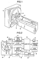
- Figure 1 is a pictorial view of a CT imaging system.
- Figure 2 is a block schematic diagram of the system illustrated in Figure 1.
- Figure 3 is a representation of a prior art helical scan, where Z-axis positions of an isocenter of each detector row are shown as a function of the gantry revolution cycle during two consecutive cardiac cycles. A scan speed of 0.8 seconds per gantry revolution and a heart rate of 60 beats per minute is represented.
- Figure 4 is a representation of an embodiment of the present invention in which data is extrapolated from other detector rows in the same or an adjacent cardiac cycle. A scan speed of 0.8 seconds per gantry revolution and a heart rate of 60 beats per minute is represented.
- Referring to Figures 1 and 2, a computed tomograph (CT)
imaging system 10 is shown as including agantry 12 representative of a "third generation" CT scanner.Gantry 12 has anx-ray source 14 that projects a beam ofx-rays 16 toward adetector array 18 on the opposite side ofgantry 12.Detector array 18 is formed bydetector elements 20 which together sense the projected x-rays that pass through anobject 22, for example a medical patient.Detector array 18 may be fabricated in a single slice or multi-slice configuration. In a multi-slice configuration,detector array 18 has several parallel rows ofelements 20. Eachdetector element 20 produces an electrical signal that represents the intensity of an impinging x-ray beam and hence the attenuation of the beam as it passes throughpatient 22. Each row ofelements 20 in a multi-slice detector configuration corresponds to an image slice parallel to a plane of fan-shapedx-ray beam 16. X-raysource 14 is configured so thatbeam 16 has sufficient thickness to impinge upon a selected number of detector rows, for example four. These detector rows are configured to be simultaneously operable to detect attenuation by parallel or nearly parallel slices ofpatient 22 during a scan. - During a scan to acquire x-ray projection data,
gantry 12 and the components mounted thereon rotate about a center ofrotation 24. Rotation ofgantry 12 and the operation ofx-ray source 14 are governed by acontrol mechanism 26 ofCT system 10.Control mechanism 26 includes anx-ray controller 28 that provides power and timing signals to x-raysource 14 and agantry motor controller 30 that controls the rotational speed and position ofgantry 12. A data acquisition system (DAS) 32 incontrol mechanism 26 samples analog data fromdetector elements 20 and converts the data to digital signals for subsequent processing. Animage reconstructor 34 receives sampled and digitized x-ray data fromDAS 32 and performs high speed image reconstruction. The reconstructed image is applied as an input to acomputer 36 which stores the image in amass storage device 38. -
Computer 36 also receives commands and scanning parameters from an operator viaconsole 40 that has a keyboard. An associated cathoderay tube display 42 allows the operator to observe the reconstructed image and other data fromcomputer 36. The operator supplied commands and parameters are used bycomputer 36 to provide control signals and information toDAS 32,x-ray controller 28 andgantry motor controller 30. In addition,computer 36 operates atable motor controller 44 which controls a motorized table 46 to positionpatient 22 ingantry 12. Particularly, table 46 moves portions ofpatient 22 throughgantry opening 48. - As explained above, Figure 3 is representative of a prior art four-slice helical scan of two consecutive cardiac cycles. In this prior art embodiment, a space results because only data spanning an angle (π+ γ)/2 is available for
peripheral segments gantry 12 revolution. (Z-axis positions correspond to translation direction of table 46 during a helical scan.) A scan rate of 0.8 seconds per revolution is selected so that a firstperipheral segment 56 scanned during one cardiac cycle at least approximately aligns with an opposite, secondperipheral segment 58 scanned during a corresponding phase φ of the next cardiac cycle. By "at least approximately aligns with," it is meant that isocenters of oppositeperipheral detector rows segments peripheral segments peripheral segments segment 50 is combined with another segment from a prior cardiac cycle, andsegment 64 is combined with another segment from a subsequent cardiac cycle. Resulting half scan data sets are then reconstructed into image slices and scored for cardiac calcification. Of course, in this embodiment, central segments are also reconstructed into image slices and scored. - By combining peripheral segments in this manner, temporal resolution of outer image slices is improved by a factor of two over that of
central slices - As noted above, perfect alignment of
peripheral segments gantry 12. For heart rates greater than 75 bpm to less than 115 bpm, scanning at agantry 12 rotation speed of 0.8 seconds per revolution is adequate for calcification scoring with four slices and a pitch of 3:1. For heart rates between 60 and 75 bpm, scanning at agantry 12 rotation speed of 0.8 to 1.0 seconds per revolution is adequate for calcification scoring with four slices and a pitch of 3:1. It will be understood that thegantry 12 rotation speed is the speed at whichx-ray source 14 anddetector array 18 rotate around the heart ofpatient 22. More generally, in an embodiment with N adjacent slices of equal thickness and a pitch of P:1, for a heart rate of B beats per minute,segments detector array 18 has only one row, i.e., ifimaging system 10 is a single slice imaging system. - In another four-slice embodiment and as shown in Figure 4, a
gantry 12 rotation speed of 0.8 seconds per revolution and a pitch of 3:1 is used for heart rates of between 60 and 75 bpm. Avalid data segment 56 ofdetector row 2B is complemented with another segment ofdata 66 obtained by extrapolation. Data to complement or "extend"segment 56 to at least a half scan dataset comprising segments more detector rows segment 56 is extended to a half scan data set 56, 66 by extrapolation from one ormore segments valid data segment 58 is complemented by a similar extrapolation to obtainsegment 68. In either variation, the extrapolation provides a half scan reconstruction at peripheral slices of the scan to avoid a gap in coverage that would otherwise occur in a prior art method. The scanned segments, including the half scan reconstructed data sets, are reconstructed into images that are scored for cardiac calcification. - In one embodiment, one or more methods of the present invention are implemented in software (or equivalently, in firmware) in
imaging system 10. For example,image reconstructor 34 is provided with software or firmware to implement one or more of the methods. At least some of parameters P, B, N and R are input viaoperator console 40 tocomputer 36. One or more, such as N, are fixed in one embodiment. In another embodiment,computer 36 calculates one of parameters P, B, N and R from the other three. - From the preceding description of various embodiments of the present invention, it is evident that high pitch multi-slice helical cardiac imaging is achieved without lost spaces between images of two cardiac cycles. Although particular embodiments of the invention have been described and illustrated in detail, it is to be clearly understood that the same is intended by way of illustration and example only and is not to be taken by way of limitation. For example, the methods and apparatus of this invention are not restricted to imaging of hearts, but rather can be applied to any object having a cyclical motion. For such other objects, B is a cycle rate in cycles per minute rather than a heart rate in beats per minute. In addition, the CT system described herein is a "third generation" system in which both the x-ray source and detector rotate with the gantry. Many other CT systems including "fourth generation" systems wherein the detector is a full-ring stationary detector and only the x-ray source rotates with the gantry, may be used if individual detector elements are corrected to provide substantially uniform responses to a given x-ray beam.
Claims (10)
- A method for scanning an object (22) with a multi-slice CT imaging system (10) having multiple detector (18) rows each having an isocenter, said method comprising the steps of:helically scanning an object (22) having a cyclical motion with a plurality of object cycles using the multi-slice CT imaging system (10) to obtain data segments (50, 52, 54, 56, 58, 60, 62, 64) including peripheral data segments (56, 58);combining data from a first peripheral data segment (56) scanned during a phase of an object cycle with a second peripheral segment (58), of the opposite side of the scan, scanned during the corresponding phase of a next object cycle to form a data set for reconstruction of an image slice; wherein the phase of the object cycle of the cyclically moving object is substantially the same in the first and the second peripheral data segments (56, 58); andreconstructing the combined data into image slices.
- A method in accordance with Claim 1 wherein reconstructing the combined data comprises reconstructing a half scan data set.
- A method in accordance with Claim 1 or 2 wherein combining data from a first peripheral data segment (56) with an opposite, second peripheral segment (58) to form a data set for reconstruction of an image slice comprises selecting peripheral segments corresponding to segments of opposite peripheral detector rows (2A, 2B) having approximately aligned isocenters in a translation direction of said helical scan.
- A method in accordance with Claim 1, 2 or 3 wherein the object has a cyclical motion, and further comprising a step of selecting a pitch P, a number of slices N, and a rotation rate R of an x-ray source (14) and detector array (18) of said helical scan so that a phase of a cycle of the cyclically moving object is substantially the same in the first segment (56) and the opposite, second segment (58).
- A method for scanning a object (22) having a cyclical motion with a multi-slice CT imaging system (10) having multiple detector (18) rows, said method comprising the steps of:helically scanning the object (22) having a cyclical motion with a plurality of object cycles using the multi-slice CT imaging system (10) to obtain data segments (50, 52, 54, 56, 58, 60, 62, 64) including first and second peripheral data segments (56, 58) at opposite sides of the scan;extrapolating data (66, 68) from the data segments to extend peripheral data segments to at least half scan data sets utilizing data obtained at the same time during an object cycle of the cyclically moving object by more than one detector row for said extrapolation wherein the phase of the object cycle of the cyclically moving object is substantially the same in the first and the second peripheral data segments (56, 58); andreconstructing image slices from the data segments, including from the half scan data sets.
- A method in accordance with Claim 5 wherein extrapolating data from the data segments to extend peripheral data segments comprises utilizing data obtained at the same time during a cycle of the cyclically moving object by more than one detector row for said extrapolation.
- A method in accordance with Claim 5 or 6 wherein the object is a patient's heart, and further comprising the step of scoring the reconstructed image slices for cardiac calcification.
- A multi-slice CT imaging system (10) having multiple detector (18) rows each having an isocenter, said system configured to:helically scan an object (22) having a cyclical motion with a plurality of object cycles to obtain data segments (50, 52, 54, 56, 58, 60, 62, 64) including peripheral data segments (56, 58);combine data from a first peripheral data segment (56) with a second peripheral segment (58), of the opposite side of the scan, scanned during the corresponding phase of a next object cycle to form a data set for reconstruction of an image slice; wherein the phase of the object cycle of the cyclically moving object is substantially the same in the first and the second peripheral data segments (56, 58); andreconstruct said combined data into image slices.
- A system (10) in accordance with Claim 8 wherein said system is configured to reconstruct said combined data comprises said system being configured to reconstruct a half scan data set.
- A system (10) in accordance with Claim 8 or 9 wherein said system is configured to combine data from a first peripheral data segment with an opposite, second peripheral segment to form a data set for reconstruction of an image slice comprises said system being configured to select peripheral segments corresponding to segments of opposite peripheral detector rows (2A, 2B) having approximately aligned isocenters in a translation direction of said helical scan.
Applications Claiming Priority (2)
| Application Number | Priority Date | Filing Date | Title |
|---|---|---|---|
| US429867 | 1995-04-27 | ||
| US09/429,867 US6597803B1 (en) | 1999-10-29 | 1999-10-29 | Hybrid reconstruction for high pitch multi-slice helical cardiac imaging |
Publications (2)
| Publication Number | Publication Date |
|---|---|
| EP1095619A1 EP1095619A1 (en) | 2001-05-02 |
| EP1095619B1 true EP1095619B1 (en) | 2007-09-05 |
Family
ID=23705048
Family Applications (1)
| Application Number | Title | Priority Date | Filing Date |
|---|---|---|---|
| EP00309410A Expired - Lifetime EP1095619B1 (en) | 1999-10-29 | 2000-10-25 | Hybrid reconstruction for high pitch multi-slice helical cardiac imaging |
Country Status (5)
| Country | Link |
|---|---|
| US (1) | US6597803B1 (en) |
| EP (1) | EP1095619B1 (en) |
| JP (1) | JP4712956B2 (en) |
| DE (1) | DE60036260T2 (en) |
| IL (1) | IL139152A (en) |
Families Citing this family (16)
| Publication number | Priority date | Publication date | Assignee | Title |
|---|---|---|---|---|
| JP4625565B2 (en) * | 2000-06-28 | 2011-02-02 | 東芝情報システム株式会社 | X-ray computed tomography system |
| US6628742B2 (en) * | 2000-09-29 | 2003-09-30 | Ge Medical Systems Global Technology Company, Llc | Cardiac helical half scan reconstructions for multiple detector row CT |
| WO2003045247A1 (en) * | 2001-11-30 | 2003-06-05 | Hitachi Medical Corporation | Cardiac tomography and tomogram using x-ray ct apparatus |
| FR2834179A1 (en) * | 2001-12-24 | 2003-06-27 | Chabunda Christophe Mwanza | Medical generation radio scanned image having odd number x-rays three phase beam producing using helix beam sweep with beams spaced central radiator object transmitting/producing four dimensions received signals |
| JP3911415B2 (en) * | 2001-12-26 | 2007-05-09 | ジーイー・メディカル・システムズ・グローバル・テクノロジー・カンパニー・エルエルシー | X-ray CT system |
| US6865250B2 (en) | 2002-12-23 | 2005-03-08 | Ge Medical Systems Global Technology Company Llc | High pitch cardiac helical scan with extended reconstruction windows |
| US6977984B2 (en) * | 2003-10-07 | 2005-12-20 | Ge Medical Systems Global Technology Company, Llc | Methods and apparatus for dynamical helical scanned image production |
| US20050201605A1 (en) * | 2004-03-11 | 2005-09-15 | Jianying Li | Methods and apparatus for CT smoothing to reduce artifacts |
| DE102004020861B4 (en) * | 2004-04-28 | 2009-10-01 | Siemens Ag | Method for the reconstruction of projection data sets with dose-reduced section-wise spiral scanning in computed tomography |
| CN1968654B (en) * | 2004-06-16 | 2012-09-26 | 株式会社日立医药 | Radiotomograph |
| JP5199081B2 (en) * | 2005-06-22 | 2013-05-15 | コーニンクレッカ フィリップス エレクトロニクス エヌ ヴィ | Suppression of band artifact in cardiac CT scan |
| JP2007236662A (en) * | 2006-03-09 | 2007-09-20 | Ge Medical Systems Global Technology Co Llc | X-ray ct system, its x-ray ct image reconstitution method and x-ray ct image photographing method |
| CN101578631B (en) * | 2007-01-08 | 2015-09-09 | 皇家飞利浦电子股份有限公司 | For to the imaging system of region of interest domain imaging comprising Moving Objects |
| US7729467B2 (en) | 2007-03-22 | 2010-06-01 | General Electric Company | Methods and systems for attentuation correction in medical imaging |
| US10492756B2 (en) * | 2016-03-29 | 2019-12-03 | NeuroLogica Corporation, a subsidiary of Samsung Electronics Co., Ltd. | Correction for drive, tilt, and scanning-speed errors in imaging systems |
| US11717252B2 (en) | 2018-08-03 | 2023-08-08 | NeuroLogica Corporation, a subsidiary of Samsung Electronics Co., Ltd. | AI-based rendered volume auto-correction for fixed and mobile x-ray imaging modalities and other imaging modalities |
Family Cites Families (17)
| Publication number | Priority date | Publication date | Assignee | Title |
|---|---|---|---|---|
| US4182311A (en) * | 1977-04-22 | 1980-01-08 | Varian Associates, Inc. | Method and system for cardiac computed tomography |
| JPH0628659B2 (en) * | 1985-09-26 | 1994-04-20 | 株式会社東芝 | X-ray CT system |
| US5270923A (en) * | 1989-11-02 | 1993-12-14 | General Electric Company | Computed tomographic image reconstruction method for helical scanning using interpolation of partial scans for image construction |
| JP3332087B2 (en) * | 1992-05-14 | 2002-10-07 | 株式会社東芝 | X-ray CT system |
| JPH06269445A (en) * | 1993-03-19 | 1994-09-27 | Hitachi Medical Corp | Helical scanning x-ray ct apparatus and r-r type x-ray ct apparatus |
| JP3510389B2 (en) * | 1995-07-10 | 2004-03-29 | ジーイー横河メディカルシステム株式会社 | X-ray CT system |
| JP4316017B2 (en) * | 1995-09-11 | 2009-08-19 | ジーイー横河メディカルシステム株式会社 | X-ray CT system |
| US5974108A (en) * | 1995-12-25 | 1999-10-26 | Kabushiki Kaisha Toshiba | X-ray CT scanning apparatus |
| JP3455041B2 (en) * | 1995-12-25 | 2003-10-06 | 株式会社東芝 | X-ray CT system |
| JP3557567B2 (en) * | 1996-07-23 | 2004-08-25 | 株式会社日立メディコ | X-ray CT system |
| CN1309548A (en) * | 1997-07-01 | 2001-08-22 | 模拟技术有限公司 | Improved helical scan computed tomography detector geometry |
| US5960056A (en) | 1997-07-01 | 1999-09-28 | Analogic Corporation | Method and apparatus for reconstructing volumetric images in a helical scanning computed tomography system with multiple rows of detectors |
| JP3124254B2 (en) * | 1997-07-24 | 2001-01-15 | ジーイー横河メディカルシステム株式会社 | Radiation tomography equipment |
| DE19740214A1 (en) * | 1997-09-12 | 1999-04-01 | Siemens Ag | Computer tomography device with spiral scanning e.g. for examination of heart |
| DE19800946A1 (en) * | 1998-01-13 | 1999-07-22 | Siemens Ag | Volume computer tomography system |
| US6154516A (en) * | 1998-09-04 | 2000-11-28 | Picker International, Inc. | Cardiac CT system |
| US6256368B1 (en) * | 1999-10-15 | 2001-07-03 | General Electric Company | Methods and apparatus for scout-based cardiac calcification scoring |
-
1999
- 1999-10-29 US US09/429,867 patent/US6597803B1/en not_active Expired - Lifetime
-
2000
- 2000-10-19 IL IL13915200A patent/IL139152A/en active IP Right Grant
- 2000-10-25 DE DE60036260T patent/DE60036260T2/en not_active Expired - Lifetime
- 2000-10-25 EP EP00309410A patent/EP1095619B1/en not_active Expired - Lifetime
- 2000-10-27 JP JP2000327894A patent/JP4712956B2/en not_active Expired - Lifetime
Non-Patent Citations (1)
| Title |
|---|
| None * |
Also Published As
| Publication number | Publication date |
|---|---|
| EP1095619A1 (en) | 2001-05-02 |
| JP4712956B2 (en) | 2011-06-29 |
| DE60036260T2 (en) | 2008-05-29 |
| US6597803B1 (en) | 2003-07-22 |
| JP2001170044A (en) | 2001-06-26 |
| IL139152A (en) | 2004-07-25 |
| DE60036260D1 (en) | 2007-10-18 |
| IL139152A0 (en) | 2001-11-25 |
Similar Documents
| Publication | Publication Date | Title |
|---|---|---|
| EP1466559B1 (en) | Methods and apparatus for cardiac imaging with conventional computed tomography | |
| US6252924B1 (en) | Method and apparatus for motion-free cardiac CT imaging | |
| US6628742B2 (en) | Cardiac helical half scan reconstructions for multiple detector row CT | |
| US6370217B1 (en) | Volumetric computed tomography system for cardiac imaging | |
| EP1605826B1 (en) | Computerized tomographic imaging system | |
| EP1092392B1 (en) | Methods and apparatus for scout-based cardiac calcification scoring | |
| EP1114616B1 (en) | Apparatus for reduced radiation computed tomography imaging | |
| EP0569238B1 (en) | Image reconstruction technique for a computed tomography system | |
| EP1095619B1 (en) | Hybrid reconstruction for high pitch multi-slice helical cardiac imaging | |
| US6434215B1 (en) | EKG-less cardiac image reconstruction | |
| EP1108392B1 (en) | Methods and apparatus for non-uniform temporal cardiac imaging | |
| JP2000107174A (en) | Image reorganization method and measurement data acquiring method | |
| EP1072224A2 (en) | Retrospective cardiac gating with cine scans on a multislice scanner | |
| EP0989521A2 (en) | Fluoroscopy image reconstruction | |
| EP1101444A2 (en) | Method and apparatus for controlling x-ray exposure during gated cardiac scanning |
Legal Events
| Date | Code | Title | Description |
|---|---|---|---|
| PUAI | Public reference made under article 153(3) epc to a published international application that has entered the european phase |
Free format text: ORIGINAL CODE: 0009012 |
|
| AK | Designated contracting states |
Kind code of ref document: A1 Designated state(s): DE NL |
|
| AX | Request for extension of the european patent |
Free format text: AL;LT;LV;MK;RO;SI |
|
| 17P | Request for examination filed |
Effective date: 20011102 |
|
| AKX | Designation fees paid |
Free format text: DE NL |
|
| 17Q | First examination report despatched |
Effective date: 20060713 |
|
| 17Q | First examination report despatched |
Effective date: 20060713 |
|
| GRAP | Despatch of communication of intention to grant a patent |
Free format text: ORIGINAL CODE: EPIDOSNIGR1 |
|
| GRAS | Grant fee paid |
Free format text: ORIGINAL CODE: EPIDOSNIGR3 |
|
| GRAA | (expected) grant |
Free format text: ORIGINAL CODE: 0009210 |
|
| AK | Designated contracting states |
Kind code of ref document: B1 Designated state(s): DE NL |
|
| RIN1 | Information on inventor provided before grant (corrected) |
Inventor name: SHEN, YUN Inventor name: WOODFORD, MARK Inventor name: ACHARYA, KISHORE Inventor name: HSIEH, JIANG Inventor name: PAN, TIN-SU |
|
| REF | Corresponds to: |
Ref document number: 60036260 Country of ref document: DE Date of ref document: 20071018 Kind code of ref document: P |
|
| PLBE | No opposition filed within time limit |
Free format text: ORIGINAL CODE: 0009261 |
|
| STAA | Information on the status of an ep patent application or granted ep patent |
Free format text: STATUS: NO OPPOSITION FILED WITHIN TIME LIMIT |
|
| 26N | No opposition filed |
Effective date: 20080606 |
|
| PGFP | Annual fee paid to national office [announced via postgrant information from national office to epo] |
Ref country code: DE Payment date: 20161027 Year of fee payment: 17 Ref country code: NL Payment date: 20161026 Year of fee payment: 17 |
|
| REG | Reference to a national code |
Ref country code: DE Ref legal event code: R119 Ref document number: 60036260 Country of ref document: DE |
|
| REG | Reference to a national code |
Ref country code: NL Ref legal event code: MM Effective date: 20171101 |
|
| PG25 | Lapsed in a contracting state [announced via postgrant information from national office to epo] |
Ref country code: NL Free format text: LAPSE BECAUSE OF NON-PAYMENT OF DUE FEES Effective date: 20171101 Ref country code: DE Free format text: LAPSE BECAUSE OF NON-PAYMENT OF DUE FEES Effective date: 20180501 |