EP1108193B1 - Corps a chaleur latente presentant une structure poreuse, et son procede de production - Google Patents
Corps a chaleur latente presentant une structure poreuse, et son procede de production Download PDFInfo
- Publication number
- EP1108193B1 EP1108193B1 EP99932839A EP99932839A EP1108193B1 EP 1108193 B1 EP1108193 B1 EP 1108193B1 EP 99932839 A EP99932839 A EP 99932839A EP 99932839 A EP99932839 A EP 99932839A EP 1108193 B1 EP1108193 B1 EP 1108193B1
- Authority
- EP
- European Patent Office
- Prior art keywords
- latent heat
- heat storage
- storage material
- carrier material
- bodies
- Prior art date
- Legal status (The legal status is an assumption and is not a legal conclusion. Google has not performed a legal analysis and makes no representation as to the accuracy of the status listed.)
- Expired - Lifetime
Links
Images


Classifications
-
- C—CHEMISTRY; METALLURGY
- C09—DYES; PAINTS; POLISHES; NATURAL RESINS; ADHESIVES; COMPOSITIONS NOT OTHERWISE PROVIDED FOR; APPLICATIONS OF MATERIALS NOT OTHERWISE PROVIDED FOR
- C09K—MATERIALS FOR MISCELLANEOUS APPLICATIONS, NOT PROVIDED FOR ELSEWHERE
- C09K5/00—Heat-transfer, heat-exchange or heat-storage materials, e.g. refrigerants; Materials for the production of heat or cold by chemical reactions other than by combustion
- C09K5/02—Materials undergoing a change of physical state when used
- C09K5/06—Materials undergoing a change of physical state when used the change of state being from liquid to solid or vice versa
- C09K5/063—Materials absorbing or liberating heat during crystallisation; Heat storage materials
-
- A—HUMAN NECESSITIES
- A47—FURNITURE; DOMESTIC ARTICLES OR APPLIANCES; COFFEE MILLS; SPICE MILLS; SUCTION CLEANERS IN GENERAL
- A47J—KITCHEN EQUIPMENT; COFFEE MILLS; SPICE MILLS; APPARATUS FOR MAKING BEVERAGES
- A47J36/00—Parts, details or accessories of cooking-vessels
- A47J36/24—Warming devices
- A47J36/30—Devices for warming by making use of burning cartridges or other chemical substances
-
- B—PERFORMING OPERATIONS; TRANSPORTING
- B65—CONVEYING; PACKING; STORING; HANDLING THIN OR FILAMENTARY MATERIAL
- B65D—CONTAINERS FOR STORAGE OR TRANSPORT OF ARTICLES OR MATERIALS, e.g. BAGS, BARRELS, BOTTLES, BOXES, CANS, CARTONS, CRATES, DRUMS, JARS, TANKS, HOPPERS, FORWARDING CONTAINERS; ACCESSORIES, CLOSURES, OR FITTINGS THEREFOR; PACKAGING ELEMENTS; PACKAGES
- B65D81/00—Containers, packaging elements, or packages, for contents presenting particular transport or storage problems, or adapted to be used for non-packaging purposes after removal of contents
- B65D81/18—Containers, packaging elements, or packages, for contents presenting particular transport or storage problems, or adapted to be used for non-packaging purposes after removal of contents providing specific environment for contents, e.g. temperature above or below ambient
-
- F—MECHANICAL ENGINEERING; LIGHTING; HEATING; WEAPONS; BLASTING
- F24—HEATING; RANGES; VENTILATING
- F24D—DOMESTIC- OR SPACE-HEATING SYSTEMS, e.g. CENTRAL HEATING SYSTEMS; DOMESTIC HOT-WATER SUPPLY SYSTEMS; ELEMENTS OR COMPONENTS THEREFOR
- F24D11/00—Central heating systems using heat accumulated in storage masses
-
- F—MECHANICAL ENGINEERING; LIGHTING; HEATING; WEAPONS; BLASTING
- F24—HEATING; RANGES; VENTILATING
- F24D—DOMESTIC- OR SPACE-HEATING SYSTEMS, e.g. CENTRAL HEATING SYSTEMS; DOMESTIC HOT-WATER SUPPLY SYSTEMS; ELEMENTS OR COMPONENTS THEREFOR
- F24D13/00—Electric heating systems
- F24D13/02—Electric heating systems solely using resistance heating, e.g. underfloor heating
-
- F—MECHANICAL ENGINEERING; LIGHTING; HEATING; WEAPONS; BLASTING
- F28—HEAT EXCHANGE IN GENERAL
- F28D—HEAT-EXCHANGE APPARATUS, NOT PROVIDED FOR IN ANOTHER SUBCLASS, IN WHICH THE HEAT-EXCHANGE MEDIA DO NOT COME INTO DIRECT CONTACT
- F28D20/00—Heat storage plants or apparatus in general; Regenerative heat-exchange apparatus not covered by groups F28D17/00 or F28D19/00
- F28D20/02—Heat storage plants or apparatus in general; Regenerative heat-exchange apparatus not covered by groups F28D17/00 or F28D19/00 using latent heat
- F28D20/023—Heat storage plants or apparatus in general; Regenerative heat-exchange apparatus not covered by groups F28D17/00 or F28D19/00 using latent heat the latent heat storage material being enclosed in granular particles or dispersed in a porous, fibrous or cellular structure
-
- Y—GENERAL TAGGING OF NEW TECHNOLOGICAL DEVELOPMENTS; GENERAL TAGGING OF CROSS-SECTIONAL TECHNOLOGIES SPANNING OVER SEVERAL SECTIONS OF THE IPC; TECHNICAL SUBJECTS COVERED BY FORMER USPC CROSS-REFERENCE ART COLLECTIONS [XRACs] AND DIGESTS
- Y02—TECHNOLOGIES OR APPLICATIONS FOR MITIGATION OR ADAPTATION AGAINST CLIMATE CHANGE
- Y02B—CLIMATE CHANGE MITIGATION TECHNOLOGIES RELATED TO BUILDINGS, e.g. HOUSING, HOUSE APPLIANCES OR RELATED END-USER APPLICATIONS
- Y02B30/00—Energy efficient heating, ventilation or air conditioning [HVAC]
-
- Y—GENERAL TAGGING OF NEW TECHNOLOGICAL DEVELOPMENTS; GENERAL TAGGING OF CROSS-SECTIONAL TECHNOLOGIES SPANNING OVER SEVERAL SECTIONS OF THE IPC; TECHNICAL SUBJECTS COVERED BY FORMER USPC CROSS-REFERENCE ART COLLECTIONS [XRACs] AND DIGESTS
- Y02—TECHNOLOGIES OR APPLICATIONS FOR MITIGATION OR ADAPTATION AGAINST CLIMATE CHANGE
- Y02E—REDUCTION OF GREENHOUSE GAS [GHG] EMISSIONS, RELATED TO ENERGY GENERATION, TRANSMISSION OR DISTRIBUTION
- Y02E60/00—Enabling technologies; Technologies with a potential or indirect contribution to GHG emissions mitigation
- Y02E60/14—Thermal energy storage
-
- Y—GENERAL TAGGING OF NEW TECHNOLOGICAL DEVELOPMENTS; GENERAL TAGGING OF CROSS-SECTIONAL TECHNOLOGIES SPANNING OVER SEVERAL SECTIONS OF THE IPC; TECHNICAL SUBJECTS COVERED BY FORMER USPC CROSS-REFERENCE ART COLLECTIONS [XRACs] AND DIGESTS
- Y02—TECHNOLOGIES OR APPLICATIONS FOR MITIGATION OR ADAPTATION AGAINST CLIMATE CHANGE
- Y02P—CLIMATE CHANGE MITIGATION TECHNOLOGIES IN THE PRODUCTION OR PROCESSING OF GOODS
- Y02P20/00—Technologies relating to chemical industry
- Y02P20/10—Process efficiency
Definitions
- the invention relates to a latent heat body with in a carrier material having receiving spaces Paraffin-based latent heat storage material.
- the invention is based on the object to specify a latent heat body, which at simple Manufacturability is highly effective, i.e. a high one Has heat storage capacity, and at the same time sufficient structural strength when heated has and in particular increased static Requirements are sufficient.
- Another goal is that the carrier material as automatically as possible with the Fills or absorbs latent heat storage material and a high retention capacity for latent heat storage material having.
- capillary inside the substrate Recording rooms designed for the latent heat storage material are and that the carrier material is a mineral with an open capillary pore structure.
- a mineral is to a absorbent solid structure thought, preferably from a gypsum material, or from a clay material, or made of sand-lime brick or silica (dolormin earths) or from any combination of these materials.
- Preferred raw materials are untreated gypsum boards, Gypsum granules, silica granules (Dolorminerden). In addition to the universal availability and the low raw product prices, these products meet increased static requirements, fire protection requirements and have a comparatively high thermal conductivity.
- Latent heat body with such solid structures compared to latent heat bodies with one Fibers existing carrier usually one lower, but sufficient for numerous applications Mass fraction of latent heat storage material, wherein preferably paraffin as latent heat storage material, but also used stearin, fat or similar substances can be. Compared to latent heat bodies with results in a higher mass fraction of latent heat storage material this for the latent heat body according to the invention especially against the background of low raw product prices of the carrier material is a cost advantage. Nevertheless, there is also an inventive one Latent heat body the possibility that the carrier material in addition to a mineral, also fiber elements contains, which is preferably distributed in the carrier material are arranged.
- the fiber elements can basically consist of organic and / or organic materials and in particular from those in EP-A-983 474 mentioned materials can be selected.
- exemplary in this context is based on organic materials such as plastic, cellulose, or wood, ceramic, mineral wool, Called plastic, cotton or sheep's wool.
- fiber elements made of plastic preferably have base materials such as polyester, polyamide, polyurethane, polyalcrylonitryl or polyolephins.
- base materials such as polyester, polyamide, polyurethane, polyalcrylonitryl or polyolephins.
- Fiber elements also made of different materials of a very different length and a very different Diameters in any combination be used.
- a carrier material that complements a mineral with an open capillary pore structure i.e. absorbent solid structure, in addition Contains fiber elements, depending on the mass proportions chosen optimized for a particular application Have properties.
- the latent heat storage material is or based on a paraffin Paraffins is constructed as in DE-OS 43 07 065 is described.
- the mass fraction of the latent heat storage material based on the total mass of the latent heat body, between 5 and 50%, preferably 25% or more preferably 40 to 50%.
- the open capillaries Pore structures due to their capillary suction are also referred to as "suction structures" in an advantageous embodiment, that therein a preferably evenly distributed volume of residual air remains, the temperature-dependent volume changes of the latent heat storage material of preferred maximum 10% of the latent heat storage material volume receives.
- the latent heat body according to the invention can through a latent heat storage material with it contained additives, such as preferably thickeners and / or a proportion of mineral oils and polymers and / or further of those in EP-A-983 474 and / or the additives mentioned in DE-OS 43 07 065 in the Be adapted to special applications that even in the event of higher than the aforementioned exceedances the melting or phase transition temperature none Sweating out the latent heat storage material from the Carrier material is possible.
- the latent heat body can have a covering, which are preferably made of a film material, such as. There is plastic or aluminum foil. It is especially one for latent heat storage material impermeable covering thought.
- wrapping may also be advantageous specifically designed to be permeable to latent heat storage material, For example, by introducing small pores into one foil material impermeable to latent heat storage material, so that a wanted "breathability" of the Wrapping is given.
- breathability can e.g. then be of advantage if the latent heat body additionally contains a hygroscopic material, because then the possibility of withdrawal from the hygroscopic Material bound moisture the area surrounding the latent heat body.
- DE-A-198 36 048 pointed out is also made to DE-A-198 36 048 pointed out.
- the carrier material in a latent heat body as a coherent structure is formed, i.e. that from the mineral with the open capillary pore structure and, if applicable, the inside additionally contained fiber elements a coherent Body with contained capillary recording spaces trained for the latent heat storage material is.
- Carrier material can through the capillary pore structure capillary recording spaces and / or conditional alone adjoining fiber elements formed capillary Recording rooms and / or through mineral compound capillary receiving spaces formed with fiber elements contain.
- an open capillary pore structure becomes a pore structure in the sense of the invention understood the connections in terms of their openness between the individual pores and between the in Pores lying close to the surface or edge Has environment and in terms of their capillarity a self-priming effect on latent heat storage material exercises.
- an open capillary pore structure even with a carrier material get that in addition to a mineral too Includes fiber elements.
- the pores or capillaries Recording spaces can be channel-like, especially with variable channel cross section and / or also contain spherical or similar cavities. However, there are also other additional forms conceivable.
- the latent heat body contains, one Latent heat partial body a carrier material partial body and that in the capillary recording rooms contained therein recorded latent heat storage material and that also existing in the capillary recording rooms Contains residual air volume.
- the latent heat body according to the invention or the absorbent solid structures can, for example, in the form of plates, building blocks, granules or other shapes for a variety of tasks be used. For example, the possibility, Slabs or building blocks independently or in a construction network (Walls). Other possible applications are a hot plate for food, use in conjunction with underfloor heating and a shipping container to which in connection discussed in more detail with the figure description becomes.
- the invention further relates to a method for the production of a latent heat body with in one carrier material having capillary receiving spaces absorbed latent heat storage material based on paraffin.
- Generic methods are not from the Pre-published EP-A-983 474 and also from the not previously published DE-A-198 36 048 known.
- the invention is based on the object specify a method by which the aforementioned Latent heat body in a simple and inexpensive way can be manufactured.
- the invention is the solution the task focused on that the latent heat storage material is liquefied that the previously liquefied Latent heat storage material on self-priming, capillary-like receiving spaces of the carrier material and that a carrier material is used which is a mineral with an open capillary Contains pore structure.
- the carrier material or the Mineral material and the latent heat storage material can preferably one or more of each Features described above.
- the mineral fiber elements be added, also one or more of the features explained above for this purpose.
- the fiber elements in the mineral be evenly distributed.
- fiber elements stir into the mineral until preferred have taken an even distribution and in further process steps, if necessary, a liquefaction first and then by thermal treatment (Firing) a desired absorbent solid structure, i.e. an open capillary pore structure, manufacture.
- the liquefaction of the latent heat storage material can done easily by supplying thermal energy, until the desired degree of liquefaction up to a possible complete liquefaction of the latent heat storage material has been achieved. It will then the previously liquefied latent heat storage material in a further process step to the self-priming, capillary-like receiving spaces of the carrier material because of the capillary suction effect the open, capillary pore structure of the carrier material an independent and ongoing one Inclusion of the latent heat storage material in the capillary Observe recording rooms of the carrier material.
- a major advantage of the invention The procedure is thus that of a mechanical action on the carrier material and the latent heat storage material be completely waived for this purpose can.
- the latent heat storage material of the method according to the invention put in a container and in it liquefied to a desired extent by supplying heat, whereupon the carrier material liquefied in the previously Latent heat storage material is immersed. By immersing it, the previously liquefied Latent heat storage material to the self-priming capillary receiving spaces of the carrier material, so that it works automatically due to the capillary suction is included in this.
- the temperature of the latent heat storage material during the introduction to the self-priming capillary-like recording rooms of the carrier material through targeted heat addition and / or removal controlled is the temperature of the latent heat storage material during the introduction to the self-priming capillary-like recording rooms of the carrier material through targeted heat addition and / or removal controlled.
- the latent heat storage material Additives are added to its flow behavior and / or the crystal structure obtained on cooling influence advantageous. For example a thickener to the latent heat storage material and / or a proportion of mineral oils and polymers is added become. Additives can also be used are like this in DE-OS43 07 065 and / or in the EP-A-983 474. Preferably with such a mass or Amount of latent heat storage material to be absorbed introduced the receiving spaces of the carrier material, the between 5 and 50%, preferably 25% and more preferably 40 to 50% of the total mass of the latent heat body is.
- the specific intake amount in a carrier material can be a targeted influence the recorded in the receiving spaces of the carrier material Mass of latent heat storage material through a suitable choice of the duration of the recording. After this period, there is the possibility the recording process by separating the still latent heat storage material remaining outside of the carrier material of the carrier material, for example removing the carrier material from an immersion bath the previously liquefied latent heat storage material, to end.
- the latent heat body or the carrier material first drained after being removed from an immersion bath and then in another possible one Process step up to a desired temperature, for example, to ambient temperature.
- an introduction of the previously liquefied latent heat storage material to the carrier material also be done in other appropriate ways can, for example, by drizzling the carrier material with latent heat storage material or by order one intended for inclusion, possibly defined, Layer thickness of latent heat storage material on the Support material.
- the latent heat body with an envelope is provided that one or more of the features described above for this purpose.
- latent heat bodies according to the invention there are due to the advantageous properties explained above and their variation possibilities numerous uses. They are, for example, in the form of plates, Building blocks or granules independently or in a composite construction (walls) used. Further possible uses in construction are storage walls, Roofs or floor storage heaters. As more advantageous Effect is achieved in that with regard on the heat storage behavior of "light” building materials by soaking or by taking up latent heat storage material, Preserved "heavy” building materials without changing their layer thickness. About that are, as can also be seen from the description below of preferred exemplary embodiments, numerous other uses of the invention Latent heat body conceivable.
- the invention further relates to a warming plate with a plate body and with a trained intake for food, in particular for rice.
- the plate base body has a latent heat body with in a carrier material having receiving spaces Paraffin-based latent heat storage material contains, with capillary within the carrier material Recording rooms designed for the latent heat storage material are and the carrier material is a mineral with an open capillary pore structure.
- the latent heat body one or more of the hotplate Features explained above.
- one or more Food receptacles one in each surface of the base plate integrated recess exhibit.
- the advantage of the warming plate according to the invention consists of an inexpensive and simple, stable structure and in a highly effective heat storage effect.
- the invention further relates to underfloor heating, in particular an electric underfloor heating, with a arranged between a bare ceiling and a cover Heating register, according to the invention a latent heat body is provided with in a recording room Carrier material recorded latent heat storage material on a paraffin basis, being within the carrier material capillary receiving spaces for the latent heat storage material are trained and the carrier material a mineral with an open capillary Contains pore structure.
- the latent heat body can over it one or more of those described above Features.
- the latent heat body is plate-like and between the bare ceiling and the heating register is arranged.
- a first layer with one made of latent heat partial bodies formed latent heat body is arranged, which also one or more of the associated with the Features explained latent heat body can have.
- the first layer described above between the plate-shaped latent heat body and the heating register is arranged.
- the underfloor heating is between the heating register and the cover a second layer with one out Latent heat partial bodies formed latent heat body provided that also one or more features, like this in connection with the invention Latent heat bodies are described, may have.
- the latent heat partial body the first and / or second layer in granular form are trained.
- the underfloor heating counts their high heat storage capacity and with that associated uniform heat output to the above located space.
- the underfloor heating also fulfills due to the structural nature of the latent heat bodies contained therein increased static Conditions.
- the invention further relates to a transport container with an outer case and one inside with one Intermediate space accommodated inner housing.
- the focus is on that in the space a latent heat body is arranged with in a carrier material having receiving spaces Paraffin-based latent heat storage material, wherein capillary receiving spaces within the carrier material trained for the latent heat storage material are and the carrier material with a mineral contains an open capillary pore structure.
- the Latent heat bodies can continue to be one or more of the features explained above.
- the invention also relates to a latent heat body according to the preamble of claim 41. Thereafter it is a latent heat body with a Carrier material and in it in capillary recording rooms absorbed latent heat storage material from paraffin base, the latent heat body a number of Contains latent heat partial bodies and a latent heat partial body a partial substrate body and therein in capillary recording rooms recorded latent heat storage material contains.
- a latent heat body is known from WO 98/53264. If provided is that a latent heat body has a number of Has latent heat partial bodies, butt the latent heat partial bodies with their outer surfaces more or less loose to each other, it also being used to trap air volumes can come between the latent heat partial bodies.
- the further subject of the invention is based on this based on the task of a generic Develop latent heat bodies in a use-advantageous manner.
- the carrier material is wood fibers and / or cardboard and / or silica granules and / or contains diatomaceous earth.
- suitable capillary receiving spaces Materials can be used accordingly that the latent heat storage material is good in any case due to the capillary suction effect of the recording rooms in the carrier material is included. Is preferred further that a temperature-dependent in the capillary recording rooms Changes in volume of the latent heat storage material up to about 10% of the latent heat storage material volume absorbing residual air volume available is.
- the carrier material can also contain fiber elements, preferably an even distribution.
- the latent heat storage material a thickener and / or contains a proportion of mineral oils and polymers.
- a latent heat body like this one described in connection with claims 1 to 15 is the carrier material with the capillary in it Recording rooms recorded latent heat storage material in terms of its outer contours from an embedding compound be surrounded.
- the carrier material can be coherent or in the form of Part carrier material bodies are present, with a partial carrier material body with the latent heat storage material contained therein as well as, if necessary, in the capillary recording spaces recorded residual air volumes a latent heat body in the sense of the present application forms.
- an embedding compound can be, for example, silicone, especially a silicone rubber, resin, concrete, Cement, plaster, mortar or other materials more comparable Act properties, whereby mixtures or Mixture of several of these substances as embedding compounds Can find use.
- Choosing the as Embedding material used or the materials can preferably be done in such a way that in coordination on the carrier material selected in the individual case a total for the application of the latent heat body advantageous overall hardness or overall rigidity of the latent heat body.
- the overall density, as well as other resulting properties such as for example thermal conductivity, heat storage capacity and the like can be affected.
- Latent heat storage material in the embedding compound preferably takes the form of mixing, whereby preferably a sheathing or impregnation with the embedding compound, which adds up to leads a network.
- a sheathing or impregnation with the embedding compound which adds up to leads a network.
- a network there is a total cohesion between the carrier material, the latent heat storage material contained therein and the embedding compound, the Carrier material contiguous or in the form of several Part carrier material body, which held together in the composite can be present.
- a latent heat body can be formed, alternatively a latent heat body also, as will be explained in more detail, out of a number of such alliances that together are stored in a storage mass and in For the purposes of the invention also referred to as conglomerates will be educated.
- the proportion of the embedding mass in the Sum of the masses of latent heat storage material, carrier material and investment material at least about 50% is lower, depending on the application Mass fractions are possible or are sensible.
- Prefers is also that the proportion of latent heat storage material, based on the common mass of latent heat storage material and carrier material, between about 40% and about 80%, and preferably about 60%.
- the share of latent heat storage material on Total weight can preferably be approximately 15% to 25%.
- the carrier material body or latent heat partial body is preferably thought that this one have granular or fibrous shape and that a typical geometric dimension of a Part of the carrier material or a latent heat partial body on the order of one or less Is millimeters to a few centimeters. Since that Latent heat storage material depending on the amount added due to the capillary action of the recording rooms predominantly inside the carrier material or the Carrier material part body is in terms of external shape and dimensions in general no essential difference between partial substrate material and given latent heat partial bodies.
- the latent heat body according to one of the design variants presented so far overall contains a number of conglomerates that each made up of a number of partial carrier material bodies, in which latent heat storage material is incorporated and that together surrounded by an embedding compound are, are formed, the conglomerates together are stored in a storage mass or from these are surrounded.
- Materials that are particularly suitable as storage materials are from the group silicone, especially silicone rubber, Resin, gypsum, cement, concrete are selected, combinations of these materials are also expedient could be. It is preferably thought of as a storage mass to choose a different material than for the Embedding mass. Depending on the individual properties of the carrier material selected in the individual case, the Embedding compound and the embedding compound can then be placed in advantageously by coordinating the proportions a desired overall property of the latent heat body be achieved, being a property in this Connection e.g. the strength, hardness, elasticity, Thermal conductivity, heat storage capacity and the like is specifically adjustable. In a preferred one Embodiment can be the proportion of the storage mass on the total mass of the latent heat body be at least about 50%.
- latent heat partial bodies one schnitzel each with latent heat storage material soaked cardboard be formed with a mass fraction of, for example, 40-80%, preferably 60% latent heat storage material based on the Total mass of the latent heat partial body.
- a conglomerate can be a number of such partial substrate material included, which are embedded together in a resin and be covered by the resin, so that a Cohesion between the sub-body parts consists.
- the mass fraction of the latent heat storage material on the total mass of the conglomerate for example. be about 30%.
- the conglomerates described above can turn, for example, concrete up to a be added about half the mixing ratio, so that the mass fraction of the latent heat storage material in the latent heat body formed up to preferably is about 15%.
- Variations on this application example may be that instead of the resin Silicone is provided and / or latent heat partial body made of silica granulate soaked with latent heat storage material are provided.
- the Structural strength of the concrete is not adversely affected is, but that this may even is positively influenced. It is essential that the Backing material due to the order of magnitude described above the substrate part through the capillaries Recording rooms have a pronounced suction effect on the Exercises latent heat storage material. While in contrast for this purpose, for example, when using powdered carrier materials the latent heat storage material attached to it always directly from the investment material would surround and lead to loss of strength would, this is through the previously explained recording of the latent heat storage material in the partial substrate bodies effectively avoided.
- a major advantage one made of carrier material, latent heat storage material and embedding mass and, if necessary, additional embedding mass formed latent heat body also exists in that the granules or the fibers of the carrier material additionally serve as reinforcement and thereby the increase static stability.
- the importance of the investment material (and possibly the storage mass) exists first in it, before they are cross-linked or hardened a certain desired fluidity or easy deformability of the with the latent heat part bodies set the batch formed for processing, so that it is rolled out or poured into shape, for example can be. After crosslinking or curing there is the function, however, in a co-determination of the resulting above Overall properties of the latent heat body.
- Latent heat body can e.g. in construction, like for example as wall, floor or ceiling elements, as street ceilings, but also as clothing parts, here as Shoe soles, as well as, for example, as elastic thin-layer elements or prostheses.
- latent heat storage material can be used on paraffin basis also 15% to 25% of the total weight of the latent heat body.
- the invention also relates to a method for the production of a latent heat body after the
- the preamble of claim 57 becomes the state of the art here also referred to WO 98/53264.
- latent heat storage material impregnated carrier material in a number can be separated from latent heat partial bodies, is further pointed out to the possibility that the latent heat partial body of the latent heat body with an envelope enclosing them together, for example one the outer contour of the film surrounding the latent heat body, can be enveloped.
- This task is first and foremost Subject of claim 57 solved, being based on it is that with latent heat storage material impregnated carrier material with an embedding compound is surrounded and that a carrier material is used, the wood fibers and / or cardboard and / or silica granules and / or contains diatomaceous earth.
- This method initially proves to be advantageous in use, than that a certain surface sealing of the Latent heat body is achieved without this Latent heat body with a covering, for example with a Foil that would have to be covered.
- Another advantage can, based on the geometric shape of the Latent heat storage material impregnated carrier material, when processing the embedding compound, a deviating desired shape of the latent heat body can be achieved by using the embedding compound accordingly adapted, possibly different material thicknesses is processed.
- a latent heat body can be used, for example starting from a single carrier material body, i.e. of a coherent carrier material become.
- a carrier material body can for example, a molded body, which previously contains the carrier material mentioned and its geometric Shape of the shape of the desired latent heat body already largely in a previous step has been adjusted.
- a shaped body by gluing and / or pressing wood fibers and / or cardboard and / or silica granules and / or diatomaceous earth becomes.
- Latent heat storage material impregnated carrier material before it with the Embedding compound is surrounded in latent heat partial body is crushed, whereby a latent heat partial body a substrate part body and accommodated therein Latent heat storage material and possibly also residual air volumes recorded therein becomes.
- a carrier material impregnated with latent heat storage material based on the carrier materials described above be used.
- Crushing can, for example by shredding, chopping or cutting, but not by grinding until Powder form.
- a further process step can then be a number of for the latent heat body intended latent heat partial body together be surrounded with the investment material.
- the latent heat partial bodies In terms of the geometrical proportions of the latent heat partial bodies it is essential that this is not until crushed to the size of powder grains, but that in the crushing an order of magnitude is obtained in the absorbency of the carrier material is preserved. With regard to the investment material it is generally preferred that this, while with Carrier material soaked in latent heat storage material is surrounded with it, in a flowable and / or in processed or in a kneadable state such condition is maintained.
- the processing can preferably include a mixing process, the Mixing of the latent heat partial bodies with the embedding compound for example by stirring and / or kneading is possible. It is further preferred that the Embedding compound after that with latent heat storage material soaked carrier material has been surrounded by it is solidified.
- the latent heat body before solidifying the Embedding compound is poured into a mold so that after later solidification of the investment Latent heat body corresponding shape is obtained.
- the latent heat body before solidifying the Embedding compound is produced, rolled out, whereby e.g. receive elastic thin-film elements can be.
- the described method for producing a Latent heat body can also be modified in this way be that from a number of carrier material partial bodies with latent heat storage material contained therein by surrounding or embedding the corresponding latent heat partial body in the embedding compound a conglomerate is formed and that a number of conglomerates together in one storage mass is stored under conglomerates in the sense the invention mergers of the type described above be understood.
- a storage mass basically that already materials proposed as embedding material Find.
- the procedure can be that after processing the investment and a desired shape of a Conglomerates initially a solidification of the investment material is brought about and that in a following Working step a number of conglomerates together is stored in the storage mass.
- the storage mass in processed in a flowable and / or kneadable form is, whereby in the following steps first a shape of the latent heat body and a subsequent one Solidification of the storage mass take place can.
- the procedure is such that the embedding compound and different materials as storage material be used.
- different physical and chemical Properties can be taken into account the physical and chemical properties of the carrier material and the latent heat storage material through a targeted coordination of the respective Quantities of latent heat bodies are produced that a tailor-made with regard to the relevant properties Possess overall behavior. So at a latent heat body by the inventive method e.g. the hardness can be adjusted continuously.
- latent heat body made of carrier material
- latent heat storage material and embedding compound are used so that relative hard paraffin-soaked diatomaceous beads in rubber-soft, silicone that crosslinks at room temperature as Embedding compound are incorporated so that a total a flexible overall structure is maintained.
- paraffin-containing, soft PAP fibers i.e. Wood fibers with a high absorbency for latent heat storage material, in concrete as Incorporate embedding compound, making one overall hard concrete storage body.
- this method can also do so be expanded that, as explained above, from Latent heat partial bodies and the embedding compound first Conglomerates in the sense of this application and this in a later step be surrounded with a storage mass, whereby the latent heat body is finally obtained becomes.
- An advantage of proposed method using embedding and, if applicable, storage mass is in particular also that latent heat body without any problems Static losses and can be produced without emulsifiers.
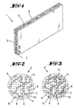
- a plate-shaped component 1 which is essentially from a latent heat body 2 according to the invention, which also has a plate shape here is.
- Latent heat body 2 with a latent heat storage material soaked plasterboard.
- the surface extending at the plate level is the latent heat body 2 with a cover 3 made of a film material, in the present case made of paper.
- the provided with the cover 3 surface of the latent heat body points in the installed state of the component 1 in Direction of a room, its demarcation or cladding component 1 is used.
- the opposite Surface of the latent heat body 2 carries one that also covers the entire surface Weather protection 4, which is also made of a film material is made.
- connection between the Latent heat body 2 and the cover 3 or the weather protection 4 is in the conventional manner with one in the each contact level introduced adhesive reached.
- cover 3 and weather protection 4 suitable connecting means such as, for example, clips, rivets or the like to fix on the latent heat body 1 and cover 3 and / or weather protection 4 to produce other suitable materials, for example made of metal foil.
- the latent heat body 2 shows an enlarged detail of the latent heat body 2 from Fig. 1. Then there is the latent heat body 2 from a carrier material 5, which is shown in the Example from a mineral with an open capillary Pore structure, in the specific embodiment made of a gypsum material, and as a coherent Structure is formed. Within the carrier material 5 there are capillary receiving spaces 6 for latent heat storage material 7, which in the example of FIG. 2 from the open capillary pore structure 8 of the gypsum material are formed or are caused by these. From the highly simplified and thus only schematic Representation shows that the open capillary Has pore structure 8 channels 9 with extensions 10, which are maze-like together through the Extend carrier material 5.
- Both channels 9 and the extensions 10 are dimensioned so that they have a capillary action on liquefied latent heat storage material exercise and insofar capillary recording rooms 6 represent for the latent heat storage material 7.
- the recording rooms 6 also their qualitative distribution in the other spatial directions. How through that respective area ratios is indicated thus the mass fraction of the latent heat storage material 7, based on the total mass of the latent heat body 2, in the example described in FIG. 2, about 25%.
- the recording rooms 6 not completely with latent heat storage material 7 are filled in, but that residual air volumes 11th remain in it, as in the example shown have an even distribution.
- the remaining air volumes 11 are dimensioned such that they are in the capillary recording rooms 6 a temperature-dependent Volume change of the latent heat storage material 7 from maximum 10% of the latent heat storage material volume take up.
- the channels 9 are only by simple Lines indicated schematically.
- FIG. 3 shows an enlarged detail of a latent heat body 2 'which differs from that shown in Fig. 2 latent heat body 2 only by additionally 5 fiber elements present in the carrier material 12 differs.
- they are the same Components of the latent heat bodies 2, 2 'in FIG. 2 and 3 labeled with the same reference numerals.
- the same too schematic Fig. 3 it can be seen that the Fiber elements 12 an elongated and irregular Have shape and with an irregular spatial Alignment approximately even within the carrier material 5 are distributed. It also becomes clear that the capillary receiving spaces 6 are not in FIG.
- Fig. 4 shows a perspective partial view with an electrical underfloor heating 13, which is arranged on a raw ceiling 14 made of concrete and the one upper cover 15 from a conventional one Material, for example from a dry coat and a floor covering, if any, has.
- a conventional one Material for example from a dry coat and a floor covering, if any, has.
- schematic heating register 16 shown provided, in which it This is an electrical heating register in one for it usual construction. It is initially between the blanket 14 and the heating register 16 a plate-shaped Latent heat body 17 arranged in terms of its components and their structural inner Arrangement and distribution with that in Fig. 2 in one Detail enlargement shown structure matches. Deviating from the embodiment shown in FIG.
- a styrofoam layer is provided is in the arrangement shown in Fig. 4 between the plate-shaped latent heat body 17 and the heating register 16 .
- the first layer 18 acts in this respect it is a filling of each other supporting latent heat partial bodies in granular form 19, which in its entirety is the latent heat body 20 form.
- the second layer 23 differs from the first layer 18 only by the type of in the respective capillary receiving spaces 6 added Latent heat storage material 7 ''. While in the first Layer 18, as stated, a latent heat storage material 7 'with a phase transition temperature of 52 ° C is recorded, the second layer 23 is different Latent heat storage material 7 '' with a different, in the present case 42 ° C and thus lower Phase transition temperature added. in principle there is also the possibility of other phase transition temperatures provided.
- Fig. 6 shows a in a perspective view first embodiment of a warming plate 26 for Foodstuffs, especially for rice.
- the warming plate 26 has a plate base body 27 with two receptacles 28 formed thereon for foods 29 on. It is based on the fact that the plate base body 27 a latent heat body 30 according to the invention contains. In the example shown, the base plate consists 27 even completely from the latent heat body 30, which has a corresponding shape.
- the latent heat body 30 As in the associated sectional view in Fig. 7 by the schematic representation of the plate base body 27 is indicated, corresponds to the internal structure of the latent heat body 30 of the schematically shown in Fig. 2 Structure.
- the latent heat body 30 also has a carrier material 5 made of a plaster material and therein contained capillary receiving spaces 6. With these these are specifically channels 9 and extension 10, which together have an open capillary pore structure 8 train.
- the latent heat body 30 a mass fraction of approximately 25% latent heat storage material, based on the total mass of the Latent heat body 30 includes and that evenly 6 residual air volumes distributed over the capillary receiving spaces 11 temperature-dependent changes in volume of the Latent heat storage material 7 of a maximum of 10% of Record the latent heat storage material volume.
- the two receptacles 28 each in the top 31 of the plate base body 27 integrated recess 32 have.
- Such a hot plate 26 can be done in such a way that it first in an oven, not shown in the drawing, to a Temperature above the phase transition temperature of the Latent heat storage material 7 is preheated, wherein in the sense of the best possible use of the heat storage capacity uniform heating of the base plate 27 should be aimed for. After completing the Heating process, the hot plate 26 from the Oven and a container, for example - as in 6 and 7 - a pot 33, in the Inside to be kept warm, not shown Food 29 are in the receptacles 28th be put in.
- the hot plate can also be brought particularly easy from a hygienic point of view be designed.
- a outer wrapper to be completely dispensed with, as well exudation of the latent heat storage material due to of the structure of the latent heat body according to the invention 30 at least when the phase transition temperature is exceeded of the latent heat storage material 7 from 30 to 40 ° K is not to be feared.
- FIGS. 6 and 7 relate to a second embodiment a warming plate 37 for food 29, especially for rice.
- the warming plate 37 has a plate base body 38, which is a latent heat body 39 contains.
- the latent heat body 39 differs itself regarding its components and its internal structure not of that in FIGS. 6 and 7 shown latent heat body 30. Differences in comparison however, regarding the external shape and in that the latent heat body 39 of one impermeable to latent heat storage material 7 Envelope 40, which in the concrete example from a well heat-conductive metal foil is formed, surrounded becomes.
- the envelope 40 has a lower part 41 and an upper part 42, which in the area of a common circumferential overlap 43 by an adhesive layer 44 are connected.
- FIG. 10 shows a transport container in a horizontal section 45 with an outer housing 46 and one received therein spaced apart with a space Inner housing 47.
- the outer housing 46 is also with thermal insulation 48, in the present case with a Polystyrene layer, lined. It is based on that in the remaining space latent heat body 49, 50 are arranged.
- each have the latent heat bodies 49, 50 a plate-like shape, with the plate plane extends perpendicular to the plane of the drawing.
- the concrete Example are four pairs of parallel contact one latent heat body 49 and one latent heat body 50 formed, the pairs in the space between the inner case 47 and the outer case 46 or the thermal insulation 48 are offset from one another are.
- the latent heat bodies 49 each limit to the inner housing 47 while the latent heat body 50 are each facing the outer housing 46. It is also provided that adjacent end faces 51, 52 of the latent heat body 49, 50 on the Inner housing 47 protruding surface areas 53 a adjacent latent heat body 49 so that no continuous voids between the latent heat body pairs consist.
- the latent heat bodies 49, 50 point in principle in the embodiment shown same components and the same internal structure like the latent heat body 2 shown in FIG. 2. Differences can only be made with regard to the phase transition temperatures of the respective latent heat storage materials 54, 55 exist, so that depending from the ambient temperature of the outer housing 46 and the desired temperature in the interior 56 of the inner housing 47 optimal due to a multi-level memory Storage effect can be set.
- the transport container 45 also has a not shown Bottom and a hinged, for example Cover on, in the bottom and in the lid area useful also a composite structure made of thermal insulation and is provided from latent heat bodies.
- the Transport container 45 shown is used for transport of a good 57 recorded in the interior 56, which during of transport is as constant as possible Keep temperature. If the temperature of the Good 57 should be above ambient temperature, can the latent heat body 49, 50 before transport heated in an oven and then into the space inserted between the outer and the inner housing become. If, however, the transport temperature should be below the ambient temperature the latent heat bodies 49, 50 accordingly before transport be cooled and then in the transport container be used.
- the transport container shown in Fig. 10 45 can thus be advantageous for different Purposes are used, each with latent heat 49, 50 are selected in which latent heat storage material 54, 55 with specifically on the concrete Transport conditions matched phase transition temperatures is included.
- each of the latent heat partial bodies 59 has one Carrier material part body 61, which is shown in the Example of a granulate from diatomaceous earth is.
- the carrier material part body 61 has one Order of magnitude at which there is a Plurality of capillary receiving spaces 62 is located in practice, the number of capillary recording spaces much higher in a partial substrate material can be as this in the highly simplified representation can express itself.
- each have latent heat storage material 63 is recorded, while maintaining residual air volumes 64.
- the capillary receiving spaces 62 within the partial substrate material 61 a labyrinthine structure in which the paraffin-based latent heat storage material 63 is included.
- the individual latent heat partial bodies 59 are surrounded together by the embedding compound 60, at which in the example shown is concrete. Due to the embedding compound 60, there is between the partial support material bodies given lasting cohesion even when the latent heat storage material is liquefied preserved.
- Fig. 13 is in a partial section compared to Figures 11 and 12 modified latent heat body 65 described as therein the individual latent heat partial bodies 59 initially in smaller numbers of an embedding compound 66, in the example shown surrounded by silicone. Conglomerates are predominant 67 formed, each of a plurality of those surrounded together with the embedding compound 66 Latent heat partial bodies 59 exist. In the example shown is through the use of silicone as an embedding compound 66 after its networking in the state of use a permanent and, within certain limits, more compliant or elastic cohesion between the latent heat partial bodies 59 of a conglomerate 67 reached.
- Vary latent heat partial body 59 per conglomerate 67 can and in particular also in the simplified Represented numbers reproduced considerably can exceed.
- individual latent heat partial body by itself from the investment compound 66 are surrounded.
- the conglomerates 67 together from an intercalation mass 68 are surrounded, which is in the embodiment is concrete.
- the storage mass 68 is accordingly a cohesion between the Conglomerates 67 produced so that the in Fig. 13 shown latent heat body 56 not externally or only insignificantly from that shown in FIGS. 11 and 12 Can distinguish latent heat body 58.
- Latent heat body 69 is another embodiment of a Latent heat body 69 according to the invention in shape shown a shoe sole.
- the latent heat body 69 has an embedding compound 60 on, but it is in the described here Example is silicone.
- the mass fraction of the silicone in the Total mass of the latent heat body 69 is about 50%. Due to the silicone used as embedding compound 60 is a permanent between the latent heat partial bodies 59 Given cohesion, the latent heat body 69 has a high degree of compliance and as a result easy deformability and good comfort properties in use.
- Partial substrate material, i.e. the cardboard schnitzel, has a variety of simplified fibers 70 made of wood or cellulose, which is a cohesion by means of a binder common in cardboard manufacture Experienced.
- capillary receiving spaces 62 are between the fibers 70 also form capillary receiving spaces 62, in which the latent heat storage material 63 Paraffin base and the residual air volumes 64 added are.
- the capillary receiving spaces can be preferred be connected.
- the shown in Example of elongated cardboard cutlets can be seen through a previous shredding of cardboard, for example be formed by tearing or cutting, where instead of the elongated shape also deviating Geometries, for example round plates of about the shape of a smaller coin can be used.
- partial substrate material can also be a have a thread-like shape and a little thicker than Be hair. It is essential that the carrier material only as far as crushing, or such a dimension has that the capillary receiving spaces 62nd are obtained so that good absorbency of the carrier material regarding the latent heat storage material 63 is guaranteed.
- Significance is also a latent heat body 1,17,20,30,39,49,50, in which the fiber elements 12 are arranged distributed in the carrier material.
- Significance is also a latent heat body 1,17,20,30,39,49,50, in which the mass fraction of the Latent heat storage material 7.7 ', 7' ', 54, 55, related on the total mass of the latent heat body 1.17.20.30.39.49.50, 5 to 50%, preferably 25% or more preferably 40 to 50%.
- Significance is also a latent heat body in which the sheath 40 for latent heat storage material 7.7 ', 7' ', 54.55 is impermeable.
- Significance is also a latent heat body in which the carrier material 5 as a coherent structure is trained.
- Latent heat body 1,17,20,30,39,49,50 which is a number of latent heat partial bodies 19, 24 contains a latent heat partial body 19,24 a substrate part body 21 and that in the 6 capillary spaces contained therein Latent heat storage material 7.7 ', 7' ', 54.55 and a Contains residual air volume 11.
- Significance is also a hot plate, in which the receptacle 28 in a surface 31 of the Plate base body 27.38 has an integrated recess.
- Underfloor heating is also important the latent heat body 1,17,20,30,39,49,50 plate-like is formed and between the raw ceiling 14 and the heating register 16 is arranged.
- Underfloor heating is also important on the top of the raw ceiling 14 a thermal insulation layer is arranged.
- Underfloor heating is also important between the bare ceiling and the heating register 16 one first layer 18 with one made of latent heat partial bodies 19 latent heat body 20 arranged is.
- Underfloor heating is also important between the heating register 16 and the cover 15 a second layer 23 with one made of latent heat partial bodies 24 latent heat body 25 arranged is.
- Underfloor heating is also important the latent heat partial bodies 19, 24 of the first 18th and / or the second 23 layer of granules are.
- Underfloor heating is also important in the latent heat partial bodies 19 of the first layer 18 a latent heat storage material 7 'with one opposite that in the latent heat partial bodies 24 of the second Layer 23 contained latent heat storage material 7 '' other phase transition temperature is included.
- phase transition temperature of the latent heat storage material 7 'of the first layer 18 is higher than that Phase transition temperature of the latent heat storage material 7 '' of the second layer 23.
- a transport container 45 is also important which in the space plate-like latent heat body 49.50 according to one or more of claims 1 to 15 or in particular are included, wherein in the to the plate plane of the plate-like latent heat body 49.50 perpendicular direction adjacent at least two latent heat bodies 49.50 with different Phase transition temperatures of each recorded therein Latent heat storage material 54.55 arranged are.
- a latent heat body in which as a mineral a gypsum material and / or a clay material and / or Lime sandstone and / or silica is used.
- a manufacturing process a latent heat body, in which a mass of Latent heat storage material 7.7 ', 7' ', 54.55 to the Recording spaces 6 of the carrier material 5 introduced which is between 5 and 50%, preferably 25% or more preferably 40 to 50% of the total mass of the Latent heat body is 1.17.20.30.39.49.50.
- Significance is also a latent heat body 1,17,20,30,39,49,50, in which the carrier material 5 with that contained in the capillary receiving spaces 6 Latent heat storage material 7.7 ', 7' ', 54.55 from is surrounded by an embedding compound.
- Significance is also a latent heat body with one Carrier material and in it in capillary recording rooms recorded latent heat storage material about Paraffin base, in which the number of latent heat partial bodies 59 together from an embedding compound 60,66 is surrounded and that the carrier material is wood fiber and / or cardboard and / or silica granulate and / or Contains diatomaceous earth.
- Significance is also a latent heat body, at which in the capillary receiving spaces 62 is a temperature-dependent one Changes in volume of the latent heat storage material 63 out of a maximum of 10% of the latent heat storage material volume absorbing residual air volume 64 is available.
- Significance is also a latent heat body, at which the carrier material fiber elements, preferably in an even distribution.
- latent heat body at which the latent heat storage material 63 is a thickening agent and / or a proportion of mineral oils and Contains polymers.
- Significance is also a latent heat body, at which the share of the embedding mass 60.66 in the Sum of the individual masses of carrier material, latent heat storage material 63 and investment material 60.66 is at least about 50%.
- Significance is also a latent heat body, at which is the proportion of the latent heat storage material 63, based on the common mass of latent heat storage material 63 and carrier material, between about 40 and is about 80%, preferably about 60%.
- a latent heat body at which is a partial substrate body 61 or a Latent heat partial body 59 a total of granular or has a fibrous shape and that a typical geometrical dimension of a partial substrate material 61 or a latent heat partial body 59 in the order of magnitude is a few millimeters to a few centimeters.
- a latent heat body 65 which contains a number of conglomerates 67, each from a number of carrier material partial bodies 61, in which latent heat storage material 63 is included and together from an embedding compound 60.66 are surrounded, are formed, and in that the conglomerates 67 together in an intercalation mass 68 are stored.
- Significance is also a latent heat body, at which is the share of the storage mass 68 in the Total mass of the latent heat body 65 at least about Is 50%.
- a latent heat body in which the latent heat storage material 63 impregnated carrier material too Latent heat partial bodies 59 is crushed, a Latent heat partial body 59 a carrier material partial body 61 and latent heat-insulating material incorporated therein 63 contains.
- a latent heat body in which a number of carrier material partial bodies 59 with those accommodated therein Latent heat storage material 63 through the common Surround or embed in the embedding compound 60.66 a conglomerate 67 is formed and that a number of conglomerates 67 together in one storage mass 68 is stored.
- Latent heat body in which the latent heat storage material 63 impregnated carrier material, before it is surrounded by the investment material, in Latent heat partial body 59 is crushed, a Latent heat partial body 59 made of a carrier material partial body 61 and latent heat storage material accommodated therein 63 and in particular a residual air volume 64 is formed, and that a plurality of latent heat partial bodies 59 together forming one Surrounded together with the embedding compound 60.66 becomes.
- a latent heat body in which the embedding compound 60.66, while that with latent heat storage material 63 soaked carrier material is surrounded with it, in a flowable and / or kneadable state is processed.
- a latent heat body in which a number of carrier material partial bodies 59 with those accommodated therein Latent heat storage material 63 through the common Surround or embed in the embedding compound 60.66 a conglomerate 67 is formed and that a number of conglomerates 67 together in one storage mass 68 is stored.
- a latent heat body in which as an embedding compound 60.66 concrete and / or silicone, in particular silicone rubber, and / or resin and / or concrete used becomes.
- a latent heat body in which as a storage mass 68 concrete and / or silicone, in particular silicone rubber, and / or resin and / or concrete is used.
Claims (64)
- Corps à chaleur latente (1, 17, 20, 30, 39, 49, 50) avec, dans un matériau support (5) présentant des cavités, un matériau logé emmagasinant la chaleur latente (7, 7', 7", 54, 55), par exemple à base de paraffine, caractérisé en ce que, à l'intérieur du matériau support (5), sont formées des cavités capillaires (6) pour le matériau emmagasinant la chaleur latente (7, 7', 7", 54, 55) et en ce que le matériau support (5) contient une substance minérale ayant une structure de pores capillaire à porosité ouverte (8).
- Corps à chaleur latente (1, 17, 20, 30, 39, 49, 50) selon la revendication 1, caractérisé en ce qu'il contient comme substance minérale, un matériau gypseux et/ou un matériau argileux et/ou du grès calcaire et/ou de la silice.
- Corps à chaleur latente (1, 17, 20, 30, 39, 49, 50) selon l'une des revendications précédentes, caractérisé en ce que le matériau support (5) contient des éléments fibreux (12).
- Corps à chaleur latente (1, 17, 20, 30, 39, 49, 50) selon l'une des revendications précédentes, caractérisé en ce que les éléments fibreux (12) sont répartis dans le matériau support.
- Corps à chaleur latente (1, 17, 20, 30, 39, 49, 50) selon l'une des revendications précédentes, caractérisé en ce que la teneur massique en matériau emmagasinant la chaleur latente (7, 7', 7", 54, 55), rapportée à la masse totale du corps à chaleur latente (1, 17, 20, 30, 39, 49, 50) est de 5 et 50%, de préférence de 25% ou plus préférentiellement encore de 40 à 50%.
- Corps à chaleur latente (1, 17, 20, 30, 39, 49, 50) selon l'une des revendications précédentes, caractérisé en ce que, dans les cavités capillaires (6), est prévu un espace d'air résiduel (11) absorbant des variations de volume dépendantes de la température du matériau emmagasinant la chaleur latente (7, 7', 7", 54, 55) d'au maximum 10% du volume de matériau emmagasinant la chaleur latente (7, 7', 7",54,55).
- Corps à chaleur latente selon l'une des revendications précédentes, caractérisé en ce que, l'espace d'air résiduel (11) est réparti de façon uniforme dans les cavités capillaires (6).
- Corps à chaleur latente (1, 17, 20, 30, 39, 49, 50) selon l'une des revendications précédentes, caractérisé en ce que le matériau emmagasinant la chaleur latente (7, 7', 7", 54, 55) contient un agent épaississant.
- Corps à chaleur latente (1, 17, 20, 30, 39, 49, 50) selon l'une des revendications précédentes, caractérisé en ce que le matériau emmagasinant la chaleur latente (7, 7', 7", 54, 55) contient une proportion d'huiles minérales et de polymères.
- Corps à chaleur latente selon l'une des revendications précédentes, caractérisé en ce que le corps à chaleur latente (1, 17, 20, 30, 39, 49, 50) présente une enveloppe (40).
- Corps à chaleur latente selon la revendication 10, caractérisé en ce que l'enveloppe (40) consiste en un matériau en forme de feuille.
- Corps à chaleur latente selon la revendication 10 ou 11, caractérisé en ce que l'enveloppe (40) est imperméable au matériau emmagasinant la chaleur latente (7, 7', 7", 54, 55).
- Corps à chaleur latente selon l'une des revendications précédentes, caractérisé en ce que le matériau support (5) est construit sous forme de structure continue.
- Corps à chaleur latente (1, 17, 20, 30, 39, 49, 50) selon l'une des revendications précédentes, caractérisé en ce que le corps à chaleur latente (1, 17, 20, 30, 39, 49, 50) contient une pluralité de parties de corps à chaleur latente (19, 24), une partie de corps à chaleur latente (19, 24) contenant une partie de matériau support (21), le matériau emmagasinant la chaleur latente (7, 7', 7", 54, 55) présent dans les cavités capillaires (6) du matériau support (21) et un espace d'air résiduel (11).
- Corps à chaleur latente (1, 17, 20, 30, 39, 49, 50) selon l'une des revendications précédentes, caractérisé en ce que le corps à chaleur latente (1, 17, 20, 30, 39, 49, 50) est construit en forme de plaque.
- Chauffe-plats (26, 37) avec un corps de base de la plaque (27, 38) munis d'un logement (28) pour un aliment (25), en particulier pour du riz, caractérisé en ce que le corps de base de la plaque (27, 38) contient un corps à chaleur latente (30, 39) selon l'une des revendications 1 à 15.
- Chauffe-plats selon la revendication 16, caractérisé en ce que le logement (28) présente un creux intégré dans la surface (31) du corps de base de la plaque (27, 38).
- Chauffage pour sol (13), en particulier chauffage électrique pour sol, avec un registre de tirage (16) disposé entre une couche de fond (14) et un revêtement (15), caractérisé par un corps à chaleur latente (1, 17, 20, 30, 39, 49, 50) selon l'une des revendications 1 à 15.
- Chauffage pour sol selon la revendication 18, caractérisé en ce que le corps à chaleur latente (1, 17, 20, 30, 39, 49, 50) est construit en forme de plaque et est disposé entre la couche de fond (14) et le registre de tirage (16).
- Chauffage pour sol selon la revendication 18 et 19, caractérisé en ce qu'une couche d'isolation thermique est disposée sur la face supérieure de la couche de fond (14).
- Chauffage pour sol (13) selon l'une des revendications 18 à 20, caractérisé en ce qu'une première couche (18) comprenant un corps à chaleur latente (20) formé de parties de corps à chaleur latente (19) selon l'une des revendications 1 à 15 est disposée entre la couche de fond et le registre de tirage (16).
- Chauffage pour sol (13) selon l'une des revendications 18 à 21, caractérisé en ce qu'une deuxième couche (23) comprenant un corps à chaleur latente (25) formé de parties de corps à chaleur latente (24) selon l'une des revendication 1 à 15, est disposée entre le registre de tirage (16) et le revêtement (15).
- Chauffage pour sol (13) selon l'une des revendications 21 ou 22, caractérisé en ce que les parties de corps à chaleur latente (19, 24) de la première (18) et/ou de la deuxième (23) couche(s) sont sous forme de granulés.
- Chauffage pour sol (13) selon l'une des revendications 22 ou 23, caractérisé en ce que, dans les parties de corps à chaleur latente (19) de la première couche (18) est contenu un matériau emmagasinant la chaleur (7') avec une température de transition de phase différente de celle du matériau emmagasinant la chaleur latente (7") contenu dans les parties de corps à chaleur latente (24) de la deuxième couche (23).
- Chauffage pour sol (13) selon l'une des revendications 22 à 24, caractérisé en ce que la température de transition de phase du matériau emmagasinant la chaleur latente (7') de la première couche (18) est supérieure à la température de transition de phase du matériau emmagasinant la chaleur latente (7") de la seconde couche (23).
- Chauffage pour sol (13) selon l'une des revendications 22 à 25, caractérisé en ce que la température de transition de phase du matériau emmagasinant la chaleur latente (7') de la première couche (18) est de 52°C et que la température de transition de phase du matériau emmagasinant la chaleur latente (7") de la seconde couche (18) est de 42°C.
- Conteneur pour le transport (45) avec une boítier externe (46) et un boítier interne (47) contenu à l'intérieur et séparé par un espace, caractérisé en ce que, dans l'espace est disposé un corps à chaleur latente (49, 50) selon l'une des revendications 1 à 15.
- Conteneur pour le transport (45) selon la revendication 27, caractérisé en ce que dans ledit espace sont contenus des corps à chaleur latente (49, 50) en forme de plaques selon l'une des revendications 1 à 15, au moins deux corps à chaleur latente (49, 50) contenant un matériau emmagasinant la chaleur (54, 55) avec des températures de changement de phases différentes étant disposés à proximité dans la direction perpendiculaire au plan de la plaque des corps à chaleur latente (49, 50) sous forme de plaques.
- Procédé de fabrication d'un corps à chaleur latente (1, 17, 20, 30, 39, 49, 50) avec un matériau emmagasinant la chaleur latente (7, 7', 7", 54, 55), par exemple à base de paraffine, logé dans un matériau support (5) présentant des cavités capillaires (6), caractérisé en ce que le matériau emmagasinant la chaleur latente (7, 7', 7'', 54, 55) est liquéfié, en ce que le matériau emmagasinant la chaleur latente (7, 7', 7'', 54, 55) précédemment liquéfié est rapproché des cavités de forme capillaire (6) auto-aspirantes du matériau support (5) et en ce qu'on utilise un matériau support (5) qui contient une substance minérale avec un structure de pores capillaire à porosité ouverte (8).
- Procédé selon la revendication 29, caractérisé en ce que des éléments fibreux (12) sont ajoutés à la substance minérale.
- Procédé selon la revendication 29 ou 30, caractérisé en ce que les éléments fibreux sont répartis dans la substance minérale de façon uniforme.
- Procédé selon l'une des revendications 29 à 31, caractérisé en ce qu'on utilise comme substance minérale un matériau gypseux et/ou un matériau argileux et/ou un grès calcaire et/ou une silice.
- Procédé selon l'une des revendications 29 à 32, caractérisé en ce que le matériau emmagasinant la chaleur latente (7, 7', 7", 54, 55) précédemment liquéfié est rapproché en absence de pression des cavités de forme capillaire (6) auto-aspirantes du matériau support (5).
- Procédé selon l'une des revendications 29 à 33, caractérisé en ce que le matériau support (5) est plongé dans le matériau emmagasinant la chaleur latente (7, 7', 7",54,55) précédemment liquéfié.
- Procédé selon l'une des revendications 29 à 34, caractérisé en ce que la température du matériau emmagasinant la chaleur latente (7, 7', 7", 54, 55) est contrôlée par apport et/ou retrait de chaleur à cet effet, pendant le rapprochement du matériau support (5) des cavités capillaires (6) auto-aspirantes.
- Procédé selon l'une des revendications 29 à 35, caractérisé en ce qu'on ajoute au matériau emmagasinant la chaleur latente (7, 7', 7", 54, 55) un agent épaississant et/ou une proportion d'huiles minérales ou de polymères.
- Procédé selon l'une des revendications 29 à 36, caractérisé en ce qu'on rapproche une masse de matériau emmagasinant la chaleur latente (7, 7', 7", 54, 55) des cavités (6) du matériau support (5) comprise entre 5 et 50%, de préférence de 25 à 50% ou encore plus préférentiellement de 40 à 50% de la masse totale du corps à chaleur latente (1, 17, 20, 30, 39, 49, 50).
- Procédé selon l'une des revendications 29 à 37, caractérisé en ce que le matériau support est égoutté et/ou refroidi après l'immersion dans le matériau emmagasinant la chaleur liquéfié.
- Procédé selon l'une des revendications 29 à 38, caractérisé en ce que le matériau à chaleur latente (1, 17, 20, 30, 39, 49, 50) est pourvu d'une enveloppe (40).
- Matériau à chaleur latente (1, 17, 20, 30, 39, 49, 50) selon l'une des revendications 1 à 15, caractérisé en ce que le matériau support (5) avec le matériau emmagasinant la chaleur latente (7, 7', 7", 54, 55) logé à l'intérieur des cavités capillaires (6), est entouré d'une masse d'enrobage.
- Matériau à chaleur latente avec un matériau support et un matériau emmagasinant la chaleur latente, par exemple à base de paraffine, logé à l'intérieur des cavités capillaires, dans lequel le corps à chaleur latente (58, 65, 69) contient une pluralité de parties de corps à chaleur latente (59), une partie de corps à chaleur latente (59) contenant une partie de matériau support (61) logeant dans ses cavités capillaires (62) un matériau emmagasinant la chaleur latente (63), caractérisé en ce que la pluralité de parties de corps à chaleur latente (59) est entourée globalement d'une masse d'enrobage (60, 66) et en ce que le matériau support contient des fibres de bois et/ou de papier et/ou de granulé de silice et/ou de terre diatomée.
- Matériau à chaleur latente selon l'une des revendications 40 et 41, caractérisé en ce que dans les cavités capillaires (62) est prévu un espace d'air résiduel(64) absorbant des variations de volume dépendantes de la température du matériau emmagasinant la chaleur latente (63) d'au maximum 10% du volume de matériau emmagasinant la chaleur latente.
- Corps à chaleur latente selon l'une des revendications 40 à 42, caractérisé en ce que le matériau support contient des éléments fibreux, de préférence répartis de façon uniforme.
- Corps à chaleur latente selon l'une des revendications 40 à 43, caractérisé en ce que le matériau emmagasinant la chaleur latente (63) contient un agent épaississant et/ou une proportion d'huiles minérales et de polymères.
- Corps à chaleur latente selon l'une des revendications 41 à 44, caractérisé en ce que la masse d'enrobage (60, 66) contient de la silicone, en particulier du silicone caoutchouc et/ou une résine et/ou du béton.
- Corps à chaleur latente selon l'une des revendications 41 à 45, caractérisé en ce que la proportion de masse d'enrobage (60, 66) est d'au moins environ 50% de la somme des masses individuelles du matériau support, du matériau emmagasinant la chaleur latente (63) et de la masse d'enrobage (60, 66).
- Corps à chaleur latente selon l'une des revendications 1 à 15 ou 40 à 46, caractérisé en ce que la proportion du matériau emmagasinant la chaleur latente (63) rapportée à la masse totale du matériau emmagasinant la chaleur (63) et du matériau support, est comprise entre environ 40 et environ 80%, et est de préférence d'environ 60%.
- Corps à chaleur latente selon l'une des revendications 1 à 15 ou 40 à 47, caractérisé en ce qu'une partie de matériau support (61), ou une partie de corps de matériau à chaleur latente (59), présente globalement une forme granuleuse ou de fibreuse, et en ce qu'une dimension géométrique typique d'une partie de matériau support (61) ou d'une partie de corps de matériau à chaleur latente (59), est de l'ordre de grandeur de quelques millimètres à quelques centimètres.
- Corps à chaleur latente selon l'une des revendications 1 à 15 ou 40 à 48, caractérisé en ce que le corps à chaleur latente (65) contient une pluralité de conglomérats (67), qui sont chacun formés d'une pluralité de parties de matériau support (61) dans lesquelles le matériau emmagasinant la chaleur latente (63) est logé et qui sont entourées ensemble d'une masse d'enrobage (60, 66), et en ce que les conglomérats (67) sont incorporés ensemble dans une masse d'incorporation (68).
- Corps à chaleur latente selon l'une des revendications 1 à 15 ou 40 à 49, caractérisé en ce que la proportion de masse d'incorporation (68) par rapport à la masse totale du corps à chaleur latente (65) est d'au moins environ 50%.
- Corps à chaleur latente selon la revendication 50, caractérisé en ce que la masse d'incorporation (68) contient de la silicone, en particulier de la caoutchouc silicone et/ou une résine et/ou du béton.
- Procédé selon l'une des revendications 29 à 39, caractérisé en ce que le matériau support imprégné de matériau emmagasinant la chaleur latente (63) est entouré d'une masse d'enrobage (60, 66).
- Procédé selon l'une des revendications 29 à 39 ou selon la revendication 52, caractérisé en ce que le matériau support imprégné de matériau emmagasinant la chaleur (63) est réduit en parties de corps à chaleur latente (59), une partie de corps à chaleur latente (59) contenant une partie de matériau support (61) et logeant à l'intérieur le matériau emmagasinant la chaleur latente (63).
- Procédé selon la revendication 53, caractérisé en ce qu'une pluralité de parties de corps à chaleur latente (59) sont entourées ensemble d'une masse d'enrobage (60, 66).
- Procédé selon l'une des revendications 29 à 39 ou 53 ou 54, caractérisé en ce que le corps à chaleur latente (58, 65, 69) est laminé avant la solidification de la masse d'enrobage (60, 66) et/ou coulé en forme.
- Procédé selon l'une des revendications 29 à 39 ou 53 à 55, caractérisé en ce qu'à partir d'une pluralité de parties de corps de matériau support (59) logeant à l'intérieur le matériau emmagasinant la chaleur latente (63), est formé par l'entourement global ou l'enrobage dans la masse d'enrobage (60, 66), un conglomérat (67) et en ce qu'une pluralité de conglomérats (67) est incorporée ensemble dans une masse d'incorporation (68).
- Procédé de fabrication d'un corps à chaleur latente avec un matériau emmagasinant la chaleur latente, par exemple à base de paraffine logé dans un matériau support présentant des cavités capillaires, dans lequel le matériau emmagasinant la chaleur latente est liquéfié est le matériau emmagasinant la chaleur latente précédemment liquéfié est rapproché des cavités de forme capillaire, auto-aspirantes, du matériau support, caractérisé en ce que le matériau support imprégné de matériau emmagasinant la chaleur latente (63) est entouré avec une masse d'enrobage (60, 66) et en ce qu'un matériau support est utilisé, qui contient dés fibres de bois et/ou de carton et/ou des granulés de silice et/ou de terre diatomée.
- Procédé selon la revendication 57, caractérisé en ce que le matériau support imprégné de matériau emmagasinant la chaleur latente (63), avant d'être entouré avec la masse d'enrobage, est broyé en parties de corps à chaleur latente (59), une partie de corps à chaleur latente (59) étant formée d'une partie de matériau support (61) et du matériau emmagasinant la chaleur latente (63) contenu à l'intérieur de ce dernier et en particulier d'un volume rempli d'air (64), et en ce que une pluralité de parties de corps à chaleur latente (59) sont entourés ensemble par formation d'un ensemble au moyen de la masse d'enrobage (60, 66).
- Procédé selon l'une des revendications 57 ou 58, caractérisé en ce que la masse d'enrobage (60, 66), pendant que le matériau support imprégné de matériau emmagasinant la chaleur latente (63) est entouré avec elle, est travaillée à l'état fluide et/ou pétrissable.
- Procédé selon l'une des revendications 57 à 59, caractérisé en ce que la masse d'enrobage (60, 66), après l'entourement du matériau support imprégné de matériau emmagasinant la chaleur latente (63), est solidifiée, en particulier séchée.
- Procédé selon l'une des revendications 57 à 60, caractérisé en ce que le corps à chaleur latente (58, 65, 69) est laminé et/ou est coulé en forme avant la solidification de la masse d'enrobage (60, 66).
- Procédé selon l'une des revendications 57 à 61, caractérisé en ce qu'un conglomérat (67) est formé à partir d'une pluralité de parties de matériau support (59) logeant à l'intérieur le matériau emmagasinant la chaleur latente (63) par entourement ou enrobage dans la masse d'enrobage (60, 66) et en ce qu'une pluralité de conglomérats (67) sont incorporés ensemble dans une masse d'incorporation (68).
- Procédé selon l'une des revendications 57 à 62, caractérisé en ce qu'on utilise comme masse d'enrobage (60, 66) du béton et/ou de la silicone, en particulier de la caoutchouc silicone, et/ou une résine et/ou du béton.
- Procédé selon l'une des revendications 62 ou 63, caractérisé en ce qu'on utilise en tant que masse d'incorporation (68) du béton et/ou de la silicone, en particulier de la caoutchouc silicone et/ou une résine et/ou du béton.
Applications Claiming Priority (5)
| Application Number | Priority Date | Filing Date | Title |
|---|---|---|---|
| DE19837730 | 1998-08-20 | ||
| DE19837730 | 1998-08-20 | ||
| DE19858794 | 1998-12-18 | ||
| DE1998158794 DE19858794A1 (de) | 1998-08-20 | 1998-12-18 | Latentwärmekörper mit Porenstruktur und Verfahren zu dessen Herstellung |
| PCT/EP1999/004730 WO2000011424A1 (fr) | 1998-08-20 | 1999-07-06 | Corps a chaleur latente presentant une structure poreuse, et son procede de production |
Publications (2)
| Publication Number | Publication Date |
|---|---|
| EP1108193A1 EP1108193A1 (fr) | 2001-06-20 |
| EP1108193B1 true EP1108193B1 (fr) | 2002-03-06 |
Family
ID=26048276
Family Applications (1)
| Application Number | Title | Priority Date | Filing Date |
|---|---|---|---|
| EP99932839A Expired - Lifetime EP1108193B1 (fr) | 1998-08-20 | 1999-07-06 | Corps a chaleur latente presentant une structure poreuse, et son procede de production |
Country Status (14)
| Country | Link |
|---|---|
| EP (1) | EP1108193B1 (fr) |
| JP (1) | JP2002523719A (fr) |
| CN (1) | CN1174214C (fr) |
| AT (1) | ATE214152T1 (fr) |
| AU (1) | AU753297B2 (fr) |
| CA (1) | CA2339728A1 (fr) |
| CZ (1) | CZ2001403A3 (fr) |
| DK (1) | DK1108193T3 (fr) |
| ES (1) | ES2170587T3 (fr) |
| NO (1) | NO20010696D0 (fr) |
| NZ (1) | NZ510634A (fr) |
| PL (1) | PL193336B1 (fr) |
| TR (1) | TR200100556T2 (fr) |
| WO (1) | WO2000011424A1 (fr) |
Cited By (1)
| Publication number | Priority date | Publication date | Assignee | Title |
|---|---|---|---|---|
| EP2295918A1 (fr) | 2002-06-03 | 2011-03-16 | ARCADIS Bouw en Vastgoed Vestiging | Procédé de chauffage et de refroidissement d'une pièce et d'un bâtiment comprenant plusieurs pièces |
Families Citing this family (9)
| Publication number | Priority date | Publication date | Assignee | Title |
|---|---|---|---|---|
| CA2488276A1 (fr) * | 2002-06-03 | 2003-12-11 | Rubitherm Gmbh | Procede de chauffage et de refroidissement d'une piece et d'un batiment comprenant plusieurs pieces |
| SE532024C2 (sv) * | 2008-02-12 | 2009-10-06 | Climatewell Ab Publ | Absorptionsmaskin med inbyggt energilager enligt matrismetoden |
| DE102013002555A1 (de) * | 2012-12-18 | 2014-06-18 | Va-Q-Tec Ag | Verfahren und Vorrichtung zur Vorkonditionierung von Latentwärmespeicherelementen |
| CN104150851B (zh) * | 2014-07-30 | 2016-03-09 | 泗阳县弘达新型墙体材料有限公司 | 一种轻质储能墙体材料及其制备方法 |
| CN104194732A (zh) * | 2014-08-22 | 2014-12-10 | 太原理工大学 | 一种硅藻土与石蜡复合相变材料的制备方法 |
| JP6604721B2 (ja) * | 2014-12-26 | 2019-11-13 | 永大産業株式会社 | 耐熱性に優れた、潜熱蓄熱材含浸蓄熱体 |
| JP6527031B2 (ja) | 2015-06-19 | 2019-06-05 | 株式会社ダイセル | 潜熱蓄熱材を含む熱輸送媒体並びに熱輸送用混合液及び熱輸送方法 |
| CN107435386A (zh) * | 2016-05-25 | 2017-12-05 | 陈昭阳 | 防火板的制作方法及其防火板 |
| AT520919B1 (de) * | 2018-05-29 | 2019-09-15 | Rep Ip Ag | Transportbehälter zum Transport von temperaturempfindlichem Transportgut |
Family Cites Families (10)
| Publication number | Priority date | Publication date | Assignee | Title |
|---|---|---|---|---|
| DE8408966U1 (de) | 1984-06-20 | Meinass, Ulrich W., 2120 Lüneburg | Kälte- und Wärmeträgerkissen | |
| AT322504B (de) * | 1969-01-08 | 1975-05-26 | Accessair Sa | Wärmespeichermasse |
| US4259401A (en) * | 1976-08-10 | 1981-03-31 | The Southwall Corporation | Methods, apparatus, and compositions for storing heat for the heating and cooling of buildings |
| US5053446A (en) * | 1985-11-22 | 1991-10-01 | University Of Dayton | Polyolefin composites containing a phase change material |
| DE3639415A1 (de) * | 1986-11-21 | 1988-06-01 | Rieber Werke Kg | Speisetransportbehaelter |
| US4988543A (en) * | 1989-09-25 | 1991-01-29 | Ecole Polytechnique | Process for incorporation of a phase change material into gypsum wallboards and other aggregate construction panels |
| DE4307065A1 (de) | 1992-12-02 | 1994-06-09 | St Speichertechnologie Gmbh | Wärmespeichermedium |
| DE19630073B4 (de) * | 1996-07-25 | 2004-04-01 | Sgl Carbon Ag | Vorrichtung zur Speicherung von Wärme oder Kälte in einem Speicherverbund aus gepreßtem Graphitexpandat und einem fest-flüssig Phasenwechselmaterial und Verfahren zu ihrer Herstellung |
| JP2001527635A (ja) | 1997-05-21 | 2001-12-25 | シューマン・サソル・ゲーエムベーハー・ウント・ツェーオー・カーゲー | 潜熱体 |
| DE19836048A1 (de) | 1998-04-29 | 1999-11-04 | Schuemann Sasol Gmbh & Co Kg | Mikrowellenaktivierbare Lastenwärmespeicherkörper |
-
1999
- 1999-07-06 CZ CZ2001403A patent/CZ2001403A3/cs unknown
- 1999-07-06 EP EP99932839A patent/EP1108193B1/fr not_active Expired - Lifetime
- 1999-07-06 CA CA002339728A patent/CA2339728A1/fr not_active Abandoned
- 1999-07-06 TR TR2001/00556T patent/TR200100556T2/xx unknown
- 1999-07-06 WO PCT/EP1999/004730 patent/WO2000011424A1/fr active IP Right Grant
- 1999-07-06 PL PL345893A patent/PL193336B1/pl not_active IP Right Cessation
- 1999-07-06 NZ NZ510634A patent/NZ510634A/xx unknown
- 1999-07-06 DK DK99932839T patent/DK1108193T3/da active
- 1999-07-06 AT AT99932839T patent/ATE214152T1/de active
- 1999-07-06 JP JP2000566635A patent/JP2002523719A/ja active Pending
- 1999-07-06 AU AU49080/99A patent/AU753297B2/en not_active Ceased
- 1999-07-06 ES ES99932839T patent/ES2170587T3/es not_active Expired - Lifetime
- 1999-07-06 CN CNB998124230A patent/CN1174214C/zh not_active Expired - Fee Related
-
2001
- 2001-02-09 NO NO20010696A patent/NO20010696D0/no not_active Application Discontinuation
Cited By (1)
| Publication number | Priority date | Publication date | Assignee | Title |
|---|---|---|---|---|
| EP2295918A1 (fr) | 2002-06-03 | 2011-03-16 | ARCADIS Bouw en Vastgoed Vestiging | Procédé de chauffage et de refroidissement d'une pièce et d'un bâtiment comprenant plusieurs pièces |
Also Published As
| Publication number | Publication date |
|---|---|
| DK1108193T3 (da) | 2002-07-01 |
| ATE214152T1 (de) | 2002-03-15 |
| AU4908099A (en) | 2000-03-14 |
| NO20010696L (no) | 2001-02-09 |
| NZ510634A (en) | 2002-09-27 |
| TR200100556T2 (tr) | 2001-07-23 |
| CA2339728A1 (fr) | 2000-03-02 |
| ES2170587T3 (es) | 2002-08-01 |
| EP1108193A1 (fr) | 2001-06-20 |
| WO2000011424A1 (fr) | 2000-03-02 |
| CN1324446A (zh) | 2001-11-28 |
| CN1174214C (zh) | 2004-11-03 |
| CZ2001403A3 (cs) | 2002-03-13 |
| PL193336B1 (pl) | 2007-02-28 |
| PL345893A1 (en) | 2002-01-14 |
| JP2002523719A (ja) | 2002-07-30 |
| AU753297B2 (en) | 2002-10-17 |
| NO20010696D0 (no) | 2001-02-09 |
Similar Documents
| Publication | Publication Date | Title |
|---|---|---|
| EP1108193B1 (fr) | Corps a chaleur latente presentant une structure poreuse, et son procede de production | |
| EP0983474B1 (fr) | Corps a chaleur latente | |
| EP3096723B1 (fr) | Dispositif chauffant comportant un moyen d'accumulation de chaleur latente | |
| DE19858794A1 (de) | Latentwärmekörper mit Porenstruktur und Verfahren zu dessen Herstellung | |
| DE1704531A1 (de) | Verfahren zur Herstellung von spezifisch leichten Koerpern | |
| DE102007025303B4 (de) | Bauelement für die Innendämmung von Gebäuden und Verfahren zu seiner Herstellung | |
| DE19813562A1 (de) | Latentwärmekörper | |
| DE102013007800B4 (de) | Trockenmörtelplatte sowie Verfahren und Verwendung einer Vorrichtung zu deren Herstellung | |
| DE602004010075T2 (de) | Verfahren zur herstellung eines wachstumssubstrats | |
| DE202015009845U1 (de) | Temperierelement | |
| DE7109069U (de) | Einlage fur kleine elektrische Hand gerate · | |
| EP1606969A2 (fr) | Piece acoustique en mousse composite | |
| EP1396325B1 (fr) | Procédé de production de panneau coupe-feu | |
| DE1771853B1 (de) | Aussenwandstein mit Waermedaemmung | |
| EP0911453A1 (fr) | Méthode pour produire des matériaux légers de construction résistante à la compression et poromère | |
| EP3156383B1 (fr) | Procédé de fabrication d'une mousse inorganique | |
| DE19615896C2 (de) | Starrer Sandkörper, Verfahren zu dessen Herstellung, dessen Verwendung und Verfahren zur Herstellung von mit Wachs umhüllten Sandkörnern | |
| DE3730208C2 (fr) | ||
| DE2041192A1 (de) | Traegerkoerper fuer die Wurzeln von Pflanzen | |
| DE19854884A1 (de) | Verfahren zum Herstellen eines wenigstens zweischichtigen Außenwandelements und dadurch hergestelltes Außenwandelement | |
| DE1704551B2 (de) | Verfahren zum Herstellen von Leicht baustoffen aus Perlen, aus geschäumtem Polystyrol oder einem gleichartigen feinkornigen Isolierstoff | |
| EP1080161B1 (fr) | Elements accumulateurs de chaleur latente pouvant etre actives par des hyperfrequences | |
| DE19634360C2 (de) | Verfahren zur Herstellung eines Komposit-Formteiles | |
| CH692579A5 (de) | Verbund-Formteil. | |
| DE4406065A1 (de) | Formkörper zur Wärme und/oder Schallisolierung |
Legal Events
| Date | Code | Title | Description |
|---|---|---|---|
| PUAI | Public reference made under article 153(3) epc to a published international application that has entered the european phase |
Free format text: ORIGINAL CODE: 0009012 |
|
| 17P | Request for examination filed |
Effective date: 20010124 |
|
| AK | Designated contracting states |
Kind code of ref document: A1 Designated state(s): AT BE CH CY DE DK ES FI FR GB GR IE IT LI LU MC NL PT SE |
|
| AX | Request for extension of the european patent |
Free format text: AL;LT;LV;MK;RO;SI |
|
| GRAG | Despatch of communication of intention to grant |
Free format text: ORIGINAL CODE: EPIDOS AGRA |
|
| GRAG | Despatch of communication of intention to grant |
Free format text: ORIGINAL CODE: EPIDOS AGRA |
|
| GRAH | Despatch of communication of intention to grant a patent |
Free format text: ORIGINAL CODE: EPIDOS IGRA |
|
| 17Q | First examination report despatched |
Effective date: 20010806 |
|
| GRAH | Despatch of communication of intention to grant a patent |
Free format text: ORIGINAL CODE: EPIDOS IGRA |
|
| REG | Reference to a national code |
Ref country code: GB Ref legal event code: IF02 |
|
| GRAA | (expected) grant |
Free format text: ORIGINAL CODE: 0009210 |
|
| AK | Designated contracting states |
Kind code of ref document: B1 Designated state(s): AT BE CH CY DE DK ES FI FR GB GR IE IT LI LU MC NL PT SE |
|
| AX | Request for extension of the european patent |
Free format text: AL;LT;LV;MK;RO;SI |
|
| PG25 | Lapsed in a contracting state [announced via postgrant information from national office to epo] |
Ref country code: GR Free format text: LAPSE BECAUSE OF FAILURE TO SUBMIT A TRANSLATION OF THE DESCRIPTION OR TO PAY THE FEE WITHIN THE PRESCRIBED TIME-LIMIT Effective date: 20020306 |
|
| REF | Corresponds to: |
Ref document number: 214152 Country of ref document: AT Date of ref document: 20020315 Kind code of ref document: T |
|
| REG | Reference to a national code |
Ref country code: CH Ref legal event code: EP |
|
| REF | Corresponds to: |
Ref document number: 59900960 Country of ref document: DE Date of ref document: 20020411 |
|
| PG25 | Lapsed in a contracting state [announced via postgrant information from national office to epo] |
Ref country code: SE Free format text: LAPSE BECAUSE OF FAILURE TO SUBMIT A TRANSLATION OF THE DESCRIPTION OR TO PAY THE FEE WITHIN THE PRESCRIBED TIME-LIMIT Effective date: 20020606 Ref country code: PT Free format text: LAPSE BECAUSE OF FAILURE TO SUBMIT A TRANSLATION OF THE DESCRIPTION OR TO PAY THE FEE WITHIN THE PRESCRIBED TIME-LIMIT Effective date: 20020606 |
|
| REG | Reference to a national code |
Ref country code: CH Ref legal event code: NV Representative=s name: R. A. EGLI & CO. PATENTANWAELTE |
|
| REG | Reference to a national code |
Ref country code: DK Ref legal event code: T3 |
|
| PG25 | Lapsed in a contracting state [announced via postgrant information from national office to epo] |
Ref country code: LU Free format text: LAPSE BECAUSE OF NON-PAYMENT OF DUE FEES Effective date: 20020706 |
|
| PG25 | Lapsed in a contracting state [announced via postgrant information from national office to epo] |
Ref country code: IE Free format text: LAPSE BECAUSE OF NON-PAYMENT OF DUE FEES Effective date: 20020708 |
|
| ET | Fr: translation filed | ||
| PG25 | Lapsed in a contracting state [announced via postgrant information from national office to epo] |
Ref country code: CY Free format text: LAPSE BECAUSE OF FAILURE TO SUBMIT A TRANSLATION OF THE DESCRIPTION OR TO PAY THE FEE WITHIN THE PRESCRIBED TIME-LIMIT Effective date: 20020731 Ref country code: BE Free format text: LAPSE BECAUSE OF NON-PAYMENT OF DUE FEES Effective date: 20020731 |
|
| REG | Reference to a national code |
Ref country code: ES Ref legal event code: FG2A Ref document number: 2170587 Country of ref document: ES Kind code of ref document: T3 |
|
| PLBE | No opposition filed within time limit |
Free format text: ORIGINAL CODE: 0009261 |
|
| STAA | Information on the status of an ep patent application or granted ep patent |
Free format text: STATUS: NO OPPOSITION FILED WITHIN TIME LIMIT |
|
| BERE | Be: lapsed |
Owner name: *SCHUMANN SASOL G.M.B.H. Effective date: 20020731 |
|
| PG25 | Lapsed in a contracting state [announced via postgrant information from national office to epo] |
Ref country code: MC Free format text: LAPSE BECAUSE OF NON-PAYMENT OF DUE FEES Effective date: 20030201 |
|
| 26N | No opposition filed |
Effective date: 20021209 |
|
| REG | Reference to a national code |
Ref country code: IE Ref legal event code: MM4A |
|
| PGFP | Annual fee paid to national office [announced via postgrant information from national office to epo] |
Ref country code: ES Payment date: 20040707 Year of fee payment: 6 |
|
| PGFP | Annual fee paid to national office [announced via postgrant information from national office to epo] |
Ref country code: DK Payment date: 20040708 Year of fee payment: 6 |
|
| PG25 | Lapsed in a contracting state [announced via postgrant information from national office to epo] |
Ref country code: ES Free format text: LAPSE BECAUSE OF NON-PAYMENT OF DUE FEES Effective date: 20050707 |
|
| PG25 | Lapsed in a contracting state [announced via postgrant information from national office to epo] |
Ref country code: DK Free format text: LAPSE BECAUSE OF NON-PAYMENT OF DUE FEES Effective date: 20050801 |
|
| REG | Reference to a national code |
Ref country code: DK Ref legal event code: EBP |
|
| REG | Reference to a national code |
Ref country code: ES Ref legal event code: FD2A Effective date: 20050707 |
|
| REG | Reference to a national code |
Ref country code: NL Ref legal event code: TD Effective date: 20101103 Ref country code: NL Ref legal event code: SD Effective date: 20101103 |
|
| REG | Reference to a national code |
Ref country code: CH Ref legal event code: PUE Owner name: RUBITHERM TECHNOLOGIES GMBH Free format text: SASOL WAX GMBH#WORTHDAMM 13-27#20457 HAMBURG (DE) -TRANSFER TO- RUBITHERM TECHNOLOGIES GMBH#SPERENBERGER STR. 5A#12277 BERLIN (DE) Ref country code: CH Ref legal event code: PFA Owner name: SASOL WAX GMBH Free format text: SCHUEMANN SASOL GMBH#WORTHDAMM 13-27#20457 HAMBURG (DE) -TRANSFER TO- SASOL WAX GMBH#WORTHDAMM 13-27#20457 HAMBURG (DE) |
|
| REG | Reference to a national code |
Ref country code: GB Ref legal event code: 732E Free format text: REGISTERED BETWEEN 20101118 AND 20101124 |
|
| REG | Reference to a national code |
Ref country code: FR Ref legal event code: TP Ref country code: FR Ref legal event code: CD |
|
| PGFP | Annual fee paid to national office [announced via postgrant information from national office to epo] |
Ref country code: FI Payment date: 20130624 Year of fee payment: 15 |
|
| PG25 | Lapsed in a contracting state [announced via postgrant information from national office to epo] |
Ref country code: FI Free format text: LAPSE BECAUSE OF NON-PAYMENT OF DUE FEES Effective date: 20140706 |
|
| PGFP | Annual fee paid to national office [announced via postgrant information from national office to epo] |
Ref country code: IT Payment date: 20150729 Year of fee payment: 17 |
|
| REG | Reference to a national code |
Ref country code: FR Ref legal event code: PLFP Year of fee payment: 18 |
|
| PGFP | Annual fee paid to national office [announced via postgrant information from national office to epo] |
Ref country code: NL Payment date: 20160711 Year of fee payment: 18 |
|
| PGFP | Annual fee paid to national office [announced via postgrant information from national office to epo] |
Ref country code: CH Payment date: 20160713 Year of fee payment: 18 |
|
| PGFP | Annual fee paid to national office [announced via postgrant information from national office to epo] |
Ref country code: AT Payment date: 20160711 Year of fee payment: 18 |
|
| REG | Reference to a national code |
Ref country code: FR Ref legal event code: PLFP Year of fee payment: 19 |
|
| PG25 | Lapsed in a contracting state [announced via postgrant information from national office to epo] |
Ref country code: IT Free format text: LAPSE BECAUSE OF NON-PAYMENT OF DUE FEES Effective date: 20160706 |
|
| REG | Reference to a national code |
Ref country code: CH Ref legal event code: PL |
|
| REG | Reference to a national code |
Ref country code: NL Ref legal event code: MM Effective date: 20170801 |
|
| REG | Reference to a national code |
Ref country code: AT Ref legal event code: MM01 Ref document number: 214152 Country of ref document: AT Kind code of ref document: T Effective date: 20170706 |
|
| PG25 | Lapsed in a contracting state [announced via postgrant information from national office to epo] |
Ref country code: NL Free format text: LAPSE BECAUSE OF NON-PAYMENT OF DUE FEES Effective date: 20170801 Ref country code: CH Free format text: LAPSE BECAUSE OF NON-PAYMENT OF DUE FEES Effective date: 20170731 Ref country code: LI Free format text: LAPSE BECAUSE OF NON-PAYMENT OF DUE FEES Effective date: 20170731 |
|
| PG25 | Lapsed in a contracting state [announced via postgrant information from national office to epo] |
Ref country code: AT Free format text: LAPSE BECAUSE OF NON-PAYMENT OF DUE FEES Effective date: 20170706 |
|
| REG | Reference to a national code |
Ref country code: FR Ref legal event code: PLFP Year of fee payment: 20 |
|
| PGFP | Annual fee paid to national office [announced via postgrant information from national office to epo] |
Ref country code: DE Payment date: 20180718 Year of fee payment: 20 Ref country code: FR Payment date: 20180719 Year of fee payment: 20 |
|
| PGFP | Annual fee paid to national office [announced via postgrant information from national office to epo] |
Ref country code: GB Payment date: 20180717 Year of fee payment: 20 |
|
| REG | Reference to a national code |
Ref country code: DE Ref legal event code: R071 Ref document number: 59900960 Country of ref document: DE |
|
| REG | Reference to a national code |
Ref country code: GB Ref legal event code: PE20 Expiry date: 20190705 |
|
| PG25 | Lapsed in a contracting state [announced via postgrant information from national office to epo] |
Ref country code: GB Free format text: LAPSE BECAUSE OF EXPIRATION OF PROTECTION Effective date: 20190705 |