EP1107120B1 - Vorrichtung mit Energieversorgungseinrichtung und Verfahren zum Anlaufen/Wiederanlaufen der Mikrostromversorgungsausfällen unterworfenen Vorrichtungen - Google Patents
Vorrichtung mit Energieversorgungseinrichtung und Verfahren zum Anlaufen/Wiederanlaufen der Mikrostromversorgungsausfällen unterworfenen Vorrichtungen Download PDFInfo
- Publication number
- EP1107120B1 EP1107120B1 EP00204129A EP00204129A EP1107120B1 EP 1107120 B1 EP1107120 B1 EP 1107120B1 EP 00204129 A EP00204129 A EP 00204129A EP 00204129 A EP00204129 A EP 00204129A EP 1107120 B1 EP1107120 B1 EP 1107120B1
- Authority
- EP
- European Patent Office
- Prior art keywords
- memory
- circuit
- restarting
- power cut
- power supply
- Prior art date
- Legal status (The legal status is an assumption and is not a legal conclusion. Google has not performed a legal analysis and makes no representation as to the accuracy of the status listed.)
- Expired - Lifetime
Links
Images

Classifications
-
- H—ELECTRICITY
- H04—ELECTRIC COMMUNICATION TECHNIQUE
- H04W—WIRELESS COMMUNICATION NETWORKS
- H04W52/00—Power management, e.g. TPC [Transmission Power Control], power saving or power classes
- H04W52/02—Power saving arrangements
- H04W52/0209—Power saving arrangements in terminal devices
- H04W52/0261—Power saving arrangements in terminal devices managing power supply demand, e.g. depending on battery level
- H04W52/0296—Power saving arrangements in terminal devices managing power supply demand, e.g. depending on battery level switching to a backup power supply
-
- H—ELECTRICITY
- H04—ELECTRIC COMMUNICATION TECHNIQUE
- H04B—TRANSMISSION
- H04B1/00—Details of transmission systems, not covered by a single one of groups H04B3/00 - H04B13/00; Details of transmission systems not characterised by the medium used for transmission
- H04B1/06—Receivers
- H04B1/16—Circuits
- H04B1/1607—Supply circuits
- H04B1/1615—Switching on; Switching off, e.g. remotely
-
- H—ELECTRICITY
- H04—ELECTRIC COMMUNICATION TECHNIQUE
- H04B—TRANSMISSION
- H04B1/00—Details of transmission systems, not covered by a single one of groups H04B3/00 - H04B13/00; Details of transmission systems not characterised by the medium used for transmission
- H04B1/38—Transceivers, i.e. devices in which transmitter and receiver form a structural unit and in which at least one part is used for functions of transmitting and receiving
- H04B1/40—Circuits
-
- H—ELECTRICITY
- H04—ELECTRIC COMMUNICATION TECHNIQUE
- H04M—TELEPHONIC COMMUNICATION
- H04M1/00—Substation equipment, e.g. for use by subscribers
- H04M1/72—Mobile telephones; Cordless telephones, i.e. devices for establishing wireless links to base stations without route selection
- H04M1/724—User interfaces specially adapted for cordless or mobile telephones
-
- Y—GENERAL TAGGING OF NEW TECHNOLOGICAL DEVELOPMENTS; GENERAL TAGGING OF CROSS-SECTIONAL TECHNOLOGIES SPANNING OVER SEVERAL SECTIONS OF THE IPC; TECHNICAL SUBJECTS COVERED BY FORMER USPC CROSS-REFERENCE ART COLLECTIONS [XRACs] AND DIGESTS
- Y02—TECHNOLOGIES OR APPLICATIONS FOR MITIGATION OR ADAPTATION AGAINST CLIMATE CHANGE
- Y02D—CLIMATE CHANGE MITIGATION TECHNOLOGIES IN INFORMATION AND COMMUNICATION TECHNOLOGIES [ICT], I.E. INFORMATION AND COMMUNICATION TECHNOLOGIES AIMING AT THE REDUCTION OF THEIR OWN ENERGY USE
- Y02D30/00—Reducing energy consumption in communication networks
- Y02D30/70—Reducing energy consumption in communication networks in wireless communication networks
Definitions
- the invention also relates to a method for starting and restarting devices subject to supply voltage interruptions.
- the invention finds its application in portable telephone devices being part of cellular type radiotelephony networks.
- the present invention proposes to make the resumption of operation more secure. of the device after a micro-cut without requiring an auxiliary battery or too many circuits complex.
- a start-up and restart process is remarkable in that when a micro-interruption has been detected, the integrity of said RAM is tested, the process of restart being lightened if the content of the RAM has not been altered during the microcut.
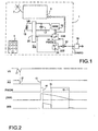
- FIG. 1 shows an apparatus 1 according to the invention.
- This device is, in the context of the example described, a portable telephone device of the cellular type.
- This apparatus includes, in particular, a transceiver circuit 3 to which is connected a antenna 7, a keyboard 5 and a processor 10 cooperating with a random access memory 12 to govern its operation.
- This device is powered by a battery 15 which provides voltage VS.
- a battery charger 16 may be present to power the device and recharge the battery. The presence of this charger is detected by a signal transmitted on a CHARG wire.
- the RAM 12 contains initialization and authentication data which allow connection to the network. When a break of more or less short duration of the supply voltage supplied by the battery occurs, the RAM 12 may not no longer be fed and its content can be erased. If it makes sense to start the boot and authentication process after a power outage to reload memory useful data for the connection, this may possibly involve input from password data using the keypad 5. You must realize that this process is long and boring for the user. We must also consider that the RAM 12 is supplied by the battery via a capacitor 17. If the micro-interruption has a short duration with respect to the discharge duration of this capacitor 17, the contents of the memory can therefore be intact and there is no need to repeat the process startup and user authentication with the network.
- the device includes a memory integrity control device.
- This control device involves the participation of processor 10 which triggers this integrity check when a micro-break has been detected.
- This detection is carried out by means of a supply distributor circuit 20 which supplies a signal RS to a branch circuit 30, sensitive to the rising edges of this signal.
- This signal RS takes the value "0" as soon as the detected voltage is lower than a threshold VR, for example half of the nominal battery voltage.
- a threshold VR for example half of the nominal battery voltage.
- the signal RS takes the value "1" after a duration equal to TS.
- a logic signal PWON is supplied by the processor 10. The value of this signal depends, among other things, on the memory integrity detection process 12. This signal sets the output signal of the branch circuit 30 to zero, when it has the value "1".
- An adder circuit 32 adds the signals to the output 30S of the circuit diverter with the signals conveyed by the CHARG wire.
- the output signal of this circuit 20 is applied to the IGN input of the processor to trigger the boot process when active.
- This rising edge detected by the processor causes a value equal to "1" of the PWON signal for a certain duration ( ⁇ 32 ms, to fix ideas), the value "0", which then takes the PWON signal, authorizes the transmission of the signal 30R at output 305, this therefore creates a pulse start which starts the integrity process of the content of memory 12. This pulse start is applied to the input IGN.
- the signal PWON takes the value "1" and therefore cuts the pulse to the IGN entry.
- the instant t6 corresponds to the decision-making which follows from the process of memory integrity check 12. Considering that the contents of memory 12 is correct, then the PWON signal keeps the value "1", otherwise it goes to zero.
- FIG. 3 shows the flow diagram of the operating steps when a rising edge of RS appears. These steps consist in forming the PWON pulse between t3 and t4 (fig. 2).
- box K1 the appearance of this rising edge is indicated; box K3 indicates that the PWON signal is set to "1”, box K5 indicates that the pulse will have a certain width and box K7 finally indicates that the signal PWON is set to "0".
- Box K10 indicates the start of the process when the IGN signal takes the value "1".
- Box K12 indicates that the PWON signal is forced to take the value "1”.
- box K15 the signal IGN is tested again. If this value is equal to "1” it means that the charger is connected, this signal "1" being supplied by the CHARG wire, via the adder circuit 32.
- the tasks assigned to this kind of situation are carried out, for example lighting of the screen etc. (box K20). If the IGN signal does not have the value "1” then we examines the integrity information contained in the memory 12 (box K22), then it is test (box K25). If everything is correct, we reconfigure the processor data, we reload registers from the data in memory 12 which saves this kind information (box K28). It should be noted that this memory is less sensitive to micro-cuts by its very nature and also by the presence of the capacitor 17.
- the integrity of the memory 12 is not respected when a value set at startup is different when read. If the logical values contained in memory 12 have a value "0", which corresponds to the initial state of memory when it has not been powered for a long time, then the memory has lost its integrity, its content has therefore been deleted.
Claims (6)
- Gerät mit:dadurch gekennzeichnet, dass es außerdem aufweist:einer Prozessorschaltung (10), an die Register angeschlossen sind,einer Versorgungsvorrichtung (15), um ihr einen Versorgungsstrom zu liefern,einer Unterbrecherschaltung (20) zur Erkennung von Ausfällen dieser Stromversorgung,einem Speicher (12), der von dieser Stromversorgung gespeist wird,einer Informationsladevorrichtung für diesen Speicher,einer Wiederanlaufvorrichtung zur Initialisierung der Vorrichtung,und dadurch, dass die Wiederanlaufvorrichtung gebildet wird aus:eine Vorrichtung zur Kontrolle der Speicherintegrität (12), bewerkstelligt über eine von der besagten Unterbrecherschaltung (20) bereitgestellte Ausfallserkennung,einer kompletten Wiederanlaufvorrichtung, wenn der besagte Speicher (12) beschädigt ist,einer geschmälerten Wiederanlaufvorrichtung, wenn der besagte Speicher (12) nicht beschädigt ist, um die besagten Register anhand der in dem besagten Speicher (12) enthaltenen Daten zu aktualisieren.
- Gerät nach Anspruch 1 zur Verwendung als tragbares Telefongeräte in einem Funktelefonnetz, das zum Anlaufen eine Identifizierungsphase im Netz erfordert, dadurch gekennzeichnet, dass die geschmälerte Wiederanlaufschaltung diese Identifizierungsphase unterlässt.
- Gerät nach einem der Ansprüche 1 oder 2, dadurch gekennzeichnet, dass die Wiederanlaufvorrichtung gesperrt ist, wenn das Gerät vor dem besagten Ausfall abgeschaltet war.
- Gerät nach einem der Ansprüche 1 oder 3, dadurch gekennzeichnet, dass eine in den besagten Speicher eingefügte Information vorgesehen ist, deren Wert von der Information, die enthalten ist, wenn dieser Speicher nicht mehr versorgt wird, abweicht.
- Gerät nach einem der Ansprüche 1 bis 4, dessen Versorgungsvorrichtung aus einem aufladbaren Akku gebildet wird und der einen Wiederanlaufeingang aufweist, dadurch gekennzeichnet, dass dieser Eingang auch mit einem Kabel verbunden ist, der ein angeschlossenes Ladegerät (16) meldet, um gegebenenfalls die Wiederanlaufvorrichtung zu sperren.
- Verfahren zum Anlaufen und Wiederanlaufen eines Gerätes nach einem der Ansprüche 1 bis 5 mit einem Prozessor, an den Register und ein Aktivspeicher (12) angeschlossen sind, dadurch gekennzeichnet, dass wenn ein Mikrostromausfall erkannt wurde, die Integrität des besagten Aktivspeichers (12) getestet wird, wobei man das Wiederanlaufen, das darin besteht, die besagten Register anhand der in dem besagten Speicher (12) enthaltenen Daten neu zu initialisieren, schmälert, wenn sein Inhalt während dem Stromausfall nicht beschädigt wurde.
Applications Claiming Priority (2)
| Application Number | Priority Date | Filing Date | Title |
|---|---|---|---|
| FR9915045 | 1999-11-30 | ||
| FR9915045 | 1999-11-30 |
Publications (2)
| Publication Number | Publication Date |
|---|---|
| EP1107120A1 EP1107120A1 (de) | 2001-06-13 |
| EP1107120B1 true EP1107120B1 (de) | 2004-02-11 |
Family
ID=9552696
Family Applications (1)
| Application Number | Title | Priority Date | Filing Date |
|---|---|---|---|
| EP00204129A Expired - Lifetime EP1107120B1 (de) | 1999-11-30 | 2000-11-22 | Vorrichtung mit Energieversorgungseinrichtung und Verfahren zum Anlaufen/Wiederanlaufen der Mikrostromversorgungsausfällen unterworfenen Vorrichtungen |
Country Status (6)
| Country | Link |
|---|---|
| US (1) | US6795913B1 (de) |
| EP (1) | EP1107120B1 (de) |
| JP (1) | JP4815560B2 (de) |
| KR (1) | KR100717627B1 (de) |
| CN (1) | CN1162979C (de) |
| DE (1) | DE60008208T2 (de) |
Families Citing this family (6)
| Publication number | Priority date | Publication date | Assignee | Title |
|---|---|---|---|---|
| US7127228B2 (en) * | 2001-12-07 | 2006-10-24 | Acer Communications And Multimedia Inc. | Portable electric device with power failure recovery and operation method thereof |
| KR100447676B1 (ko) | 2002-12-11 | 2004-09-08 | 주식회사 팬택앤큐리텔 | 단말기 오프 방지 회로 및 방법 |
| JP3765544B1 (ja) * | 2004-11-26 | 2006-04-12 | 株式会社ソニー・コンピュータエンタテインメント | バッテリ、及び認証要求装置 |
| KR100670005B1 (ko) * | 2005-02-23 | 2007-01-19 | 삼성전자주식회사 | 모바일 플랫폼을 위한 메모리의 무결성을 원격으로 확인하는 확인장치 및 그 시스템 그리고 무결성 확인 방법 |
| US7595607B2 (en) * | 2005-12-20 | 2009-09-29 | General Electric Company | Battery charging system and methods |
| CN100428203C (zh) * | 2006-11-23 | 2008-10-22 | 北京飞天诚信科技有限公司 | 基于非易失性存储的便携式设备的实现掉电保护的方法 |
Family Cites Families (21)
| Publication number | Priority date | Publication date | Assignee | Title |
|---|---|---|---|---|
| JPS51120644A (en) * | 1975-04-15 | 1976-10-22 | Matsushita Electric Ind Co Ltd | Memory content protection circuit |
| JPS58225743A (ja) * | 1982-06-23 | 1983-12-27 | Toshiba Corp | 無線電話装置 |
| JPS59192740U (ja) * | 1983-06-02 | 1984-12-21 | パイオニア株式会社 | コンピユ−タ装置 |
| US4530027A (en) * | 1984-03-30 | 1985-07-16 | Sperry Corporation | Power failure protector circuit |
| US4652139A (en) * | 1986-04-16 | 1987-03-24 | Chrysler Motors Corporation | Electronic non-volatile elapsed time meter |
| JPH0624335B2 (ja) * | 1987-02-27 | 1994-03-30 | 日本電気株式会社 | 表示付選択呼出受信機 |
| JP2503284B2 (ja) * | 1989-12-28 | 1996-06-05 | 松下電器産業株式会社 | 回線保持装置 |
| US5390322A (en) * | 1991-02-01 | 1995-02-14 | O'brien; Michael J. | Apparatus and method for retaining cycle memory in electronic sterilizer controls |
| DE4111859A1 (de) * | 1991-04-11 | 1992-10-15 | Robert Seuffer Gmbh & Co | Elektrische schaltung zum aufrechterhalten des zustandes eines zaehlers bei unterbrechung der versorgungsspannung |
| TW327488U (en) * | 1991-05-29 | 1998-02-21 | Video Tech Eng | Digital cordless telephone apparatus |
| JP3036982B2 (ja) * | 1992-07-17 | 2000-04-24 | 松下電器産業株式会社 | コードレス電話装置 |
| JP3120387B2 (ja) * | 1992-08-04 | 2000-12-25 | ユニデン株式会社 | コードレス電話装置 |
| JPH06216827A (ja) * | 1993-01-20 | 1994-08-05 | Mitsubishi Electric Corp | 携帯電話装置 |
| JPH07118677B2 (ja) * | 1993-04-16 | 1995-12-18 | 日本電気株式会社 | 無線選択呼出受信機 |
| JPH08129511A (ja) * | 1994-09-05 | 1996-05-21 | Canon Inc | メモリのバックアップ方法及びメモリのバックアップ回路並びに該回路を有するファクシミリ装置 |
| JP3309266B2 (ja) * | 1995-02-28 | 2002-07-29 | 京セラ株式会社 | 電池パックの充電端子短絡防止回路 |
| US5691629A (en) * | 1995-07-13 | 1997-11-25 | The United States Of America As Represented By The Secretary Of The Air Force | Non-volatile power supply having energy efficient DC/DC voltage converters with a small storage capacitor |
| KR0168529B1 (ko) * | 1996-02-12 | 1999-02-01 | 김광호 | 간이 교환장치의 정전시 메모리 보존 회로 |
| US5708589A (en) * | 1996-04-08 | 1998-01-13 | Vaughn Manufacturing Corporation | Error recovery system for an energy controller for an electric water heater |
| JP2786169B2 (ja) * | 1996-06-25 | 1998-08-13 | 静岡日本電気株式会社 | 表示付無線選択呼出受信機 |
| US6265849B1 (en) * | 1998-12-29 | 2001-07-24 | U.S. Philips Corporation | Electrical apparatus comprising a battery and method of detecting the disconnection of a battery |
-
2000
- 2000-11-22 DE DE60008208T patent/DE60008208T2/de not_active Expired - Lifetime
- 2000-11-22 US US09/718,248 patent/US6795913B1/en not_active Expired - Lifetime
- 2000-11-22 EP EP00204129A patent/EP1107120B1/de not_active Expired - Lifetime
- 2000-11-27 CN CNB001280945A patent/CN1162979C/zh not_active Expired - Fee Related
- 2000-11-27 KR KR1020000070822A patent/KR100717627B1/ko not_active IP Right Cessation
- 2000-11-28 JP JP2000361055A patent/JP4815560B2/ja not_active Expired - Fee Related
Also Published As
| Publication number | Publication date |
|---|---|
| KR20010051968A (ko) | 2001-06-25 |
| JP2001245045A (ja) | 2001-09-07 |
| EP1107120A1 (de) | 2001-06-13 |
| JP4815560B2 (ja) | 2011-11-16 |
| DE60008208T2 (de) | 2004-12-02 |
| KR100717627B1 (ko) | 2007-05-15 |
| US6795913B1 (en) | 2004-09-21 |
| CN1298228A (zh) | 2001-06-06 |
| CN1162979C (zh) | 2004-08-18 |
| DE60008208D1 (de) | 2004-03-18 |
Similar Documents
| Publication | Publication Date | Title |
|---|---|---|
| EP2463833B1 (de) | Verfahren und Vorrichtung zur Ausführungskontrolle für interne Funktionen und Funktionen von geschützten Anwendungen auf Mikrochipkarten von mobilen Endgeräten | |
| EP1107120B1 (de) | Vorrichtung mit Energieversorgungseinrichtung und Verfahren zum Anlaufen/Wiederanlaufen der Mikrostromversorgungsausfällen unterworfenen Vorrichtungen | |
| CA2692300C (fr) | Procede et systeme de gestion de coupures d'alimentation electrique a bord d'un aeronef | |
| EP0849660A1 (de) | Tragbares elektronisches Gerät mit Detektorvorrichtung der Änderungen einer Versorgungsspannung | |
| FR2571872A1 (fr) | Dispositif d'alimentation electrique de microprocesseurs | |
| EP0815527B1 (de) | Koppler zur kommunikationsverwaltung zwischen einem tragbaren träger und einer datenaustauschvorrichtung und datenaustauschvorrichtung dafür | |
| WO2021105089A1 (fr) | Procédé de mise à jour de système numérique | |
| EP1017148B1 (de) | Elektrische Vorrichtung, die eine Batterie beinhaltet und Verfahren zum Erkennen der Trennung von einer Batterie | |
| FR2526601A1 (fr) | Systeme d'alimentation en energie d'un appareil destine a cooperer avec un support electronique amovible tel qu'une carte et appareil equipe d'un tel systeme | |
| EP1614310B1 (de) | Anordnung mit einem mobil telefon und ein zusatzspeicher | |
| CN114338908B (zh) | 一种sim卡恢复方法、装置、芯片及模组设备 | |
| EP3545384B1 (de) | System zur verwaltung des stromverbrauchs in einer vorrichtung | |
| WO2005013580A1 (fr) | Procede, terminal mobile, cartes et programmes informatiques permettant a une application embarquee sur un terminal de communiquer avec une application residente en carte sim | |
| EP4361768A1 (de) | Leistungsverwaltung in einem nfc-nahfeldkommunikationssteuergerät | |
| FR3058271A1 (fr) | Procede et systeme de controle de charge d'une batterie d'un equipement electrique | |
| WO2009004176A2 (fr) | Systeme de surveillance d ' unites de communications a travers l ' internet et procède correspondant | |
| CN106815026B (zh) | 一种防止误开机的方法和设备 | |
| EP0593690A1 (de) | Verfahren und vorrichtung zur reduzierung des leistungsverbrauchs in einem öffentlichem fernsprechgerät | |
| EP4266065A1 (de) | Stromzähler zur erkennung einer betrügerischen öffnung | |
| EP1175016B1 (de) | Integrierte Schaltung mit aktiven und inaktiven Betriebsmodus und Vorrichtung die diese Schaltung enthält | |
| BE1004724A3 (fr) | Dispositif de surveillance de la proximite d'un objet portatif. | |
| WO2009071505A1 (fr) | Dispositif de contrôle du fonctionnement d'un module électronique de radiocommunication et circuit électronique correspondant | |
| FR2861510A1 (fr) | Dispositif de protection contre les courts-circuits | |
| EP1146655A1 (de) | System und Verfahren zur automatischen Inbetriebhaltung eines tragbaren Kommunikationsgerätes | |
| FR2937447A1 (fr) | Objet portable a microprecesseur et memoire non volatile securisee et dispositif externe connectable a un objet portable. |
Legal Events
| Date | Code | Title | Description |
|---|---|---|---|
| PUAI | Public reference made under article 153(3) epc to a published international application that has entered the european phase |
Free format text: ORIGINAL CODE: 0009012 |
|
| AK | Designated contracting states |
Kind code of ref document: A1 Designated state(s): DE FR GB IT |
|
| AX | Request for extension of the european patent |
Free format text: AL;LT;LV;MK;RO;SI |
|
| 17P | Request for examination filed |
Effective date: 20011213 |
|
| AKX | Designation fees paid |
Free format text: DE FR GB IT |
|
| 17Q | First examination report despatched |
Effective date: 20020528 |
|
| GRAH | Despatch of communication of intention to grant a patent |
Free format text: ORIGINAL CODE: EPIDOS IGRA |
|
| RIC1 | Information provided on ipc code assigned before grant |
Ipc: 7G 06F 11/07 A Ipc: 7H 04B 1/16 B Ipc: 7H 04M 1/725 B |
|
| GRAS | Grant fee paid |
Free format text: ORIGINAL CODE: EPIDOSNIGR3 |
|
| GRAA | (expected) grant |
Free format text: ORIGINAL CODE: 0009210 |
|
| RIN1 | Information on inventor provided before grant (corrected) |
Inventor name: RICORDEL, ELOI |
|
| AK | Designated contracting states |
Kind code of ref document: B1 Designated state(s): DE FR GB IT |
|
| REG | Reference to a national code |
Ref country code: GB Ref legal event code: FG4D Free format text: NOT ENGLISH |
|
| REF | Corresponds to: |
Ref document number: 60008208 Country of ref document: DE Date of ref document: 20040318 Kind code of ref document: P |
|
| GBT | Gb: translation of ep patent filed (gb section 77(6)(a)/1977) |
Effective date: 20040311 |
|
| PLBE | No opposition filed within time limit |
Free format text: ORIGINAL CODE: 0009261 |
|
| STAA | Information on the status of an ep patent application or granted ep patent |
Free format text: STATUS: NO OPPOSITION FILED WITHIN TIME LIMIT |
|
| 26N | No opposition filed |
Effective date: 20041112 |
|
| REG | Reference to a national code |
Ref country code: GB Ref legal event code: 732E |
|
| REG | Reference to a national code |
Ref country code: FR Ref legal event code: TP |
|
| PGFP | Annual fee paid to national office [announced via postgrant information from national office to epo] |
Ref country code: DE Payment date: 20101025 Year of fee payment: 11 |
|
| PGFP | Annual fee paid to national office [announced via postgrant information from national office to epo] |
Ref country code: GB Payment date: 20101026 Year of fee payment: 11 Ref country code: IT Payment date: 20101105 Year of fee payment: 11 |
|
| PGFP | Annual fee paid to national office [announced via postgrant information from national office to epo] |
Ref country code: FR Payment date: 20111205 Year of fee payment: 12 |
|
| GBPC | Gb: european patent ceased through non-payment of renewal fee |
Effective date: 20121122 |
|
| REG | Reference to a national code |
Ref country code: FR Ref legal event code: ST Effective date: 20130731 |
|
| PG25 | Lapsed in a contracting state [announced via postgrant information from national office to epo] |
Ref country code: IT Free format text: LAPSE BECAUSE OF NON-PAYMENT OF DUE FEES Effective date: 20121122 |
|
| REG | Reference to a national code |
Ref country code: DE Ref legal event code: R119 Ref document number: 60008208 Country of ref document: DE Effective date: 20130601 |
|
| PG25 | Lapsed in a contracting state [announced via postgrant information from national office to epo] |
Ref country code: DE Free format text: LAPSE BECAUSE OF NON-PAYMENT OF DUE FEES Effective date: 20130601 |
|
| PG25 | Lapsed in a contracting state [announced via postgrant information from national office to epo] |
Ref country code: FR Free format text: LAPSE BECAUSE OF NON-PAYMENT OF DUE FEES Effective date: 20121130 Ref country code: GB Free format text: LAPSE BECAUSE OF NON-PAYMENT OF DUE FEES Effective date: 20121122 |