EP3545384B1 - System zur verwaltung des stromverbrauchs in einer vorrichtung - Google Patents
System zur verwaltung des stromverbrauchs in einer vorrichtung Download PDFInfo
- Publication number
- EP3545384B1 EP3545384B1 EP17822140.4A EP17822140A EP3545384B1 EP 3545384 B1 EP3545384 B1 EP 3545384B1 EP 17822140 A EP17822140 A EP 17822140A EP 3545384 B1 EP3545384 B1 EP 3545384B1
- Authority
- EP
- European Patent Office
- Prior art keywords
- module
- appliance
- supply
- wireless communication
- bss
- Prior art date
- Legal status (The legal status is an assumption and is not a legal conclusion. Google has not performed a legal analysis and makes no representation as to the accuracy of the status listed.)
- Active
Links
Images


Classifications
-
- G—PHYSICS
- G05—CONTROLLING; REGULATING
- G05B—CONTROL OR REGULATING SYSTEMS IN GENERAL; FUNCTIONAL ELEMENTS OF SUCH SYSTEMS; MONITORING OR TESTING ARRANGEMENTS FOR SUCH SYSTEMS OR ELEMENTS
- G05B19/00—Program-control systems
- G05B19/02—Program-control systems electric
- G05B19/04—Program control other than numerical control, i.e. in sequence controllers or logic controllers
- G05B19/042—Program control other than numerical control, i.e. in sequence controllers or logic controllers using digital processors
- G05B19/0428—Safety, monitoring
-
- G—PHYSICS
- G06—COMPUTING OR CALCULATING; COUNTING
- G06F—ELECTRIC DIGITAL DATA PROCESSING
- G06F1/00—Details not covered by groups G06F3/00 - G06F13/00 and G06F21/00
- G06F1/26—Power supply means, e.g. regulation thereof
- G06F1/32—Means for saving power
- G06F1/3203—Power management, i.e. event-based initiation of a power-saving mode
- G06F1/3234—Power saving characterised by the action undertaken
- G06F1/3287—Power saving characterised by the action undertaken by switching off individual functional units in the computer system
-
- G—PHYSICS
- G06—COMPUTING OR CALCULATING; COUNTING
- G06F—ELECTRIC DIGITAL DATA PROCESSING
- G06F1/00—Details not covered by groups G06F3/00 - G06F13/00 and G06F21/00
- G06F1/26—Power supply means, e.g. regulation thereof
- G06F1/263—Arrangements for using multiple switchable power supplies, e.g. battery and AC
-
- H—ELECTRICITY
- H02—GENERATION; CONVERSION OR DISTRIBUTION OF ELECTRIC POWER
- H02J—ELECTRIC POWER NETWORKS; CIRCUIT ARRANGEMENTS OR SYSTEMS FOR SUPPLYING OR DISTRIBUTING ELECTRIC POWER; SYSTEMS FOR STORING ELECTRIC ENERGY
- H02J13/00—Circuit arrangements for providing remote monitoring or remote control of equipment in a power distribution network
-
- H—ELECTRICITY
- H04—ELECTRIC COMMUNICATION TECHNIQUE
- H04B—TRANSMISSION
- H04B7/00—Radio transmission systems, i.e. using radiation field
- H04B7/02—Diversity systems; Multi-antenna system, i.e. transmission or reception using multiple antennas
-
- H—ELECTRICITY
- H04—ELECTRIC COMMUNICATION TECHNIQUE
- H04W—WIRELESS COMMUNICATION NETWORKS
- H04W52/00—Power management, e.g. Transmission Power Control [TPC] or power classes
- H04W52/02—Power saving arrangements
- H04W52/0209—Power saving arrangements in terminal devices
- H04W52/0261—Power saving arrangements in terminal devices managing power supply demand, e.g. depending on battery level
- H04W52/0274—Power saving arrangements in terminal devices managing power supply demand, e.g. depending on battery level by switching on or off the equipment or parts thereof
- H04W52/028—Power saving arrangements in terminal devices managing power supply demand, e.g. depending on battery level by switching on or off the equipment or parts thereof switching on or off only a part of the equipment circuit blocks
-
- G—PHYSICS
- G05—CONTROLLING; REGULATING
- G05B—CONTROL OR REGULATING SYSTEMS IN GENERAL; FUNCTIONAL ELEMENTS OF SUCH SYSTEMS; MONITORING OR TESTING ARRANGEMENTS FOR SUCH SYSTEMS OR ELEMENTS
- G05B2219/00—Program-control systems
- G05B2219/20—Pc systems
- G05B2219/21—Pc I-O input output
- G05B2219/21154—Over current protection
-
- H—ELECTRICITY
- H04—ELECTRIC COMMUNICATION TECHNIQUE
- H04W—WIRELESS COMMUNICATION NETWORKS
- H04W40/00—Communication routing or communication path finding
- H04W40/005—Routing actions in the presence of nodes in sleep or doze mode
-
- Y—GENERAL TAGGING OF NEW TECHNOLOGICAL DEVELOPMENTS; GENERAL TAGGING OF CROSS-SECTIONAL TECHNOLOGIES SPANNING OVER SEVERAL SECTIONS OF THE IPC; TECHNICAL SUBJECTS COVERED BY FORMER USPC CROSS-REFERENCE ART COLLECTIONS [XRACs] AND DIGESTS
- Y02—TECHNOLOGIES OR APPLICATIONS FOR MITIGATION OR ADAPTATION AGAINST CLIMATE CHANGE
- Y02D—CLIMATE CHANGE MITIGATION TECHNOLOGIES IN INFORMATION AND COMMUNICATION TECHNOLOGIES [ICT], I.E. INFORMATION AND COMMUNICATION TECHNOLOGIES AIMING AT THE REDUCTION OF THEIR OWN ENERGY USE
- Y02D10/00—Energy efficient computing, e.g. low power processors, power management or thermal management
-
- Y—GENERAL TAGGING OF NEW TECHNOLOGICAL DEVELOPMENTS; GENERAL TAGGING OF CROSS-SECTIONAL TECHNOLOGIES SPANNING OVER SEVERAL SECTIONS OF THE IPC; TECHNICAL SUBJECTS COVERED BY FORMER USPC CROSS-REFERENCE ART COLLECTIONS [XRACs] AND DIGESTS
- Y02—TECHNOLOGIES OR APPLICATIONS FOR MITIGATION OR ADAPTATION AGAINST CLIMATE CHANGE
- Y02D—CLIMATE CHANGE MITIGATION TECHNOLOGIES IN INFORMATION AND COMMUNICATION TECHNOLOGIES [ICT], I.E. INFORMATION AND COMMUNICATION TECHNOLOGIES AIMING AT THE REDUCTION OF THEIR OWN ENERGY USE
- Y02D30/00—Reducing energy consumption in communication networks
- Y02D30/70—Reducing energy consumption in communication networks in wireless communication networks
Definitions
- the invention relates to a system for managing electrical consumption in a device comprising a battery protected by a fuse, the device being able to be electrically powered by a mains supply or by the battery, the power supply by the battery being intended to relay the mains supply in the event of a mains power failure.
- the invention further relates to a method for managing the electrical consumption of said device implemented by said device.
- Some devices such as internet gateways, include backup batteries allowing them to continue operating despite a power outage.
- Backup batteries have internal protections to secure devices. These protections are provided, among other things, by fuses. Sizing these fuses is a sensitive point when designing devices. In fact, backup batteries are considered a power source.
- This current source can be high or limited.
- a high current source implies mechanical design constraints in the devices involved. Thus, for a device that must include a high energy source, it may be necessary to provide an envelope against fire and thus reduce (or even eliminate) ventilation openings in mechanical walls. This has the effect of preventing natural convection and requires the addition of a forced ventilation system, which is generally considered unacceptable for certain devices such as walkways.
- a device that may include a power limited power source may implement ventilation holes. Using a fuse with a low current limit allows batteries to be considered as a power-limited current source and thus alleviates mechanical design constraints.
- a reduction in device performance not only impacts the device.
- remote equipment with which the device is connected, can also be impacted by the reduction in performance of said device.
- the system ensures that the safety fuse is not damaged in the event of a mains power outage.
- the monitoring and detection module comprises means for comparing a voltage representative of a supply voltage of the device to a predefined reference voltage, an interruption of the mains power supply being detected when the predefined reference voltage is greater than the voltage representative of the supply voltage of the device.
- the other hardware modules comprise a plurality of wireless communication modules each managing at least one wireless communication link, each wireless link being associated with at least one remote device
- the method comprises: checking if the mains power to the device is restored; when the mains power is not restored: obtain information representative of a first wireless communication module which can be cut off and transmit to each remote equipment associated with a wireless link managed by the first wireless communication module a message comprising information representative of said wireless link; cutting off the power supply to the first wireless communication module; and, regularly check whether mains power has been restored.
- said message further comprises a list indicating to each remote device associated with a wireless link managed by the first wireless communication module at least one wireless link to which to migrate.
- the wireless link to which to migrate is an existing wireless link managed by a second wireless communication module or a temporary wireless link created by a second wireless communication module following detection of the outage mains power supply.
- the method further comprises: saving an identifier of each remote equipment associated with a wireless link managed by the first wireless communication module; and, use the saved identifiers to allow a second wireless communication module to treat as a priority each remote device concerned by said identifiers if they attempt to migrate to a wireless link managed by said second wireless communication module.
- the method when the mains power is restored, the method further comprises: authorizing the re-powering of each hardware module of the disconnected device upon detection of the interruption of the mains power; and, transmit a message to each remote device affected by the power outage of the first wireless communication module indicating that each wireless link managed by the first wireless communication module has been reactivated.
- each message is transmitted to each remote device affected by the shutdown of the first wireless communication module according to a point-to-point communication mode or according to a point-to-multipoint communication mode or according to a multicast communication mode.
- the multicast communication mode is used during detection of a mains power outage, and the point-to-point communication mode or the point-to-multipoint communication mode is used during detection restoration of mains power.
- the invention relates to a computer program, comprising instructions for implementing, by an apparatus, steps of the method according to the second aspect when said program is executed by a processor of said apparatus.
- the invention relates to storage means storing a computer program comprising instructions for implementing, by an apparatus, steps of the method according to the second aspect when said program is executed by a processor of said device.
- the invention is described below in an internet gateway context.
- the invention could however be implemented in another context, in any device comprising a battery capable of relaying a mains power supply, the device being communicating or not.
- part of the invention concerns activation/deactivation of Wi-Fi modules and management of remote equipment associated with Wi-Fi links managed by these Wi-Fi modules.
- the invention could just as well adapt to other communication modules than Wi-Fi modules, such as for example Bluetooth or ZigBee modules.
- FIG. 1 schematically illustrates a device 1 implementing the invention.
- device 1 is a gateway.
- Gateway 1 includes a core system 10 which we detail in relation to the Figs. 2 and 3 managing all the functionalities of the gateway 1, a mains power module 13, a battery power module 14, a transition module 12, ensuring a passage from mains power to battery power when mains power is switched off and a switch from battery power to mains power when mains power is turned back on.
- Gateway 1 also includes an electrical consumption management system 11 which we detail below in relation to the Figs. 4 and 5 .
- remote equipment 2A, 2B and 2C are connected to gateway 1 for example by Wi-Fi links 3A, 3B and 3C.
- FIG. 2 schematically illustrates an example of hardware architecture of the core system 10 whose electrical consumption is managed by an electrical consumption management system 11 according to the invention.
- the core system 10 then comprises, connected by a communication bus 100: a processor or CPU (“Central Processing Unit” in English) 101; a RAM (“Random Access Memory” in English) 102; a ROM (“Read Only Memory” in English) 103; a storage unit such as a hard disk or a storage media reader, such as an SD card reader (“Secure Digital” in English) 104; a communication interface 105 allowing the device 10 to communicate with other devices or devices.
- the core system 10 further comprises a USB module (Universal Serial Bus: “Universal Serial Bus” in Anglo-Saxon terminology) 106 capable of reading, for example, a USB key and a display module 107 such as a screen with liquid crystals.
- USB module Universal Serial Bus: “Universal Serial Bus” in Anglo-Saxon terminology
- the processor 101 is capable of executing instructions loaded into the RAM 102 from the ROM 103, an external memory (not shown), a storage medium (such as an SD card), or a communications network. When the device 10 is powered on, the processor 101 is capable of reading instructions from the RAM 102 and executing them. These instructions form a computer program causing the implementation by the processor 101 of the process steps described below in relation to the Figs. 6 And 8 .
- the steps of the processes described in relation to the Figs. 6 And 8 can be implemented in software form by executing a set of instructions by a programmable machine, for example a DSP (“Digital Signal Processor” in English) or a microcontroller, or be implemented in hardware form by a machine or a dedicated component, for example an FPGA (“Field-Programmable Gate Array” in English) or an ASIC (“Application-Specific Integrated Circuit” in English).
- a programmable machine for example a DSP (“Digital Signal Processor” in English) or a microcontroller
- FPGA Field-Programmable Gate Array
- ASIC Application-Specific Integrated Circuit
- FIG. 3 schematically illustrates a detail of the communication module 105 whose electrical consumption is managed by an electrical consumption management system 11 according to the invention.
- the communication module 105 comprises, connected by the communication bus 100, a first Wi-Fi module 1050 implementing the IEEE802.11b, g or n standards, a second Wi-Fi module 1051 implementing the IEEE802.11a standard , n or ac and a third Wi-Fi module 1052 identical to the Wi-Fi module 1051.
- the remote equipment 2A, 2B and 2C are connected to the gateway 1 by Wi-Fi links 3A, 3B and 3C managed respectively by the modules Wi-Fi 1050, 1051 and 1052.
- Each Wi-Fi module is capable of managing at least one Wi-Fi connection commonly called BSS (Basic Service Set: “Basic Service Set” in Anglo-Saxon terminology).
- Remote equipment that manages to connect to a BSS is said to be associated with this BSS.
- the remote device then has access to the services offered by the gateway through the BSS with which it is associated.
- the remote equipment 2A is associated with the BSS 3A ( ie with the Wi-Fi link 3A) managed by the Wi-Fi module 1050.
- the remote equipment 2B is associated with the BSS 3B (ie with the Wi-Fi link 3B) managed by the Wi-Fi module 1051.
- the remote equipment 2C is associated with the BSS 3C ( ie the Wi-Fi link 3C) managed by the Wi-Fi module 1052.
- the communication module 105 further comprises an IP-compatible voice over network communication module 1053 (“Internet Protocol” in Anglo-Saxon terminology) commonly called VoIP (“Voice over IP” in Anglo-Saxon terminology), an Ethernet module. 1054, an SFP module (Small Form-factor Pluggable: “Small Form-factor Pluggable” in English terminology) 1055 and an xDSL (ADSL, SDSL, etc.) module (asymmetric/symmetric digital access line: “ Asymmetric/Symetric Digital Subscriber Line” in Anglo-Saxon terminology) 1056.
- IP-compatible voice over network communication module 1053 (“Internet Protocol” in Anglo-Saxon terminology) commonly called VoIP (“Voice over IP” in Anglo-Saxon terminology)
- Ethernet module 1054
- SFP module Small Form-factor Pluggable: “Small Form-factor Pluggable” in English terminology
- xDSL ADSL, SDSL, etc.
- asymmetric/symmetric digital access line “ Asymmetric/Symetric Digital Subscriber Line” in Anglo-Saxon terminology
- gateway 1 In an example of use of gateway 1, during a mains power outage, it is considered that the Voice over IP functionality must be preserved in order to allow a user to be able to contact emergency services even in the event of a power outage. 'power supply. In order to ensure this functionality, certain hardware modules of the core system 10 are essential, ie the voice functionality over IP could not be ensured without these hardware modules. Other hardware modules such as Wi-Fi modules may be degraded but must remain functional.
- An objective of the electrical consumption management system 11 is to act on the optional modules and the secondary modules to reduce the electrical consumption of the gateway during a mains power outage.
- FIG. 4 schematically illustrates a first example of an electrical consumption management system 11 according to the invention.
- the electrical consumption management system 11 is placed in a context of use.
- the battery power module 14 includes at least one battery.
- Each battery of the battery power module 14 is protected by a fuse, hereinafter called a safety fuse , capable of supporting a maximum power supply current of the gateway 1 for a predefined duration T.
- the Wi-Fi 1050 module is shown in detail including a processing 10501, an antenna 10504 and an antenna 10505 and, associated respectively with the antenna 10504, a power amplifier 10502 and with the antenna 10505, a power amplifier 10503. It is known that a power amplifier consumes electric energy. A significant reduction in consumption would therefore be obtained if this type of hardware module were cut.
- the power consumption management system 11 comprises a mains power outage detection module 111 and a power consumption reduction module 112.
- the mains power outage detection module 111 and the electrical consumption reduction module 112 are entirely material modules (“hardware” in Anglo-Saxon terminology). Modules 111 and 112 therefore operate independently of any interpretation of machine instructions ( ie they are not software modules and they do not receive software instructions), and are able to react in a time less than the predefined duration T.
- the mains power failure detection module 111 monitors an input voltage of the gateway 1. When a power failure of the gateway 1 occurs, this input voltage drops. This fall can then be detected.
- the mains power outage detection module 111 can be implemented in different forms.
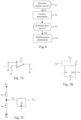
- FIG. 7A, 7B and 7C schematically illustrate three examples of modules for detecting a failure of the mains power supply 111 adapted to the invention.
- the mains power outage detection module 111 is implemented by an operational amplifier 71 mounted as a simple comparator.
- An input voltage V+ is compared to an input voltage V-.
- the voltage V+ is representative of the input voltage of gateway 1 to be monitored.
- the voltage V- is representative of a voltage reference.
- the voltage reference is obtained via a voltage regulator whose output voltage (i.e. the reference voltage) is always the same whether the gateway is powered by the mains power module 13 or the power supply module by battery 14.
- An output ( ie an output voltage) V s of the operational amplifier 71 depends on a sign of a subtraction between V + and V -.
- the mains power outage detection module 111 is implemented by a voltage supervisor 72.
- the voltage supervisor 72 includes a RESET output which is set to zero when a monitored voltage V in falls below a reference voltage predefined in the voltage supervisor 72.
- the module for detecting a failure of the mains power supply 111 is implemented by a voltage divider bridge coupled to a logic gate 74.
- the voltage divider bridge is formed of a resistor 75 and a resistor 76 (for example of 75kQ and 27kQ respectively).
- An output V out of logic gate 74 changes state when an input voltage V in coming from the voltage divider bridge and representative of the voltage to be monitored passes below a predefined reference voltage.
- the reduction in electrical consumption is obtained by cutting the electrical power supply to certain hardware modules included in the gateway 1.
- the electrical consumption reduction module 112 ensures these electrical power supply cuts.
- the electrical consumption reduction module 112 can for example be implemented by a PMOS power transistor controlled by the output of the module for detecting a failure of the mains power supply 111.
- the output of the module for detecting a power outage cutting off the mains power supply 111 therefore controls the PMOS power transistor and, in the event of a mains power cut, causes an opening of a power supply circuit of each hardware module which must be cut off.
- each power amplifier included in the Wi-Fi modules 1050, 1051 and 1052 includes an activation/deactivation input making it possible to activate or deactivate said power amplifier.
- the output of the mains power outage detection module 111 directly deactivates the power amplifier 10502 via the activation/deactivation input thereof.
- Each activation/deactivation input therefore constitutes means for reducing the electrical consumption of gateway 1.
- the Wi-Fi 1050 module is one of the secondary modules whose operation may be degraded. From a global point of view, upon detection of a power cut by the module 111, the module 112 cuts the power supply to all the optional modules and degrades the operation of certain secondary modules so as to ensure that the gateway consumes a supply current lower than the maximum supply current that the safety fuse can withstand.
- the secondary modules whose operation is degraded are predefined. Furthermore, the way in which the operation of these modules is degraded is also predefined. For example, when the secondary modules are Wi-Fi modules 1050, 1051 and 1052, the degradation consists of only powering one power amplifier for each Wi-Fi module. In this way, each Wi-Fi module cannot effectively use only an antenna.
- FIG. 5 schematically illustrates a second example of an electrical consumption management system 11 according to the invention.
- Fig. 5 differs from the Fig. 4 in that the simplified version of the core system 10 in which only the Wi-Fi module 1050 is represented this time shows the processor 101 and the communication bus 100.
- the mains power outage detection module 111 includes a module 500, called a lock.
- the lock 500 makes it possible to authorize or not authorize a power cut to a hardware module of the gateway 1.
- the power supply to a hardware module of the gateway 1 is only really cut off by the module 112 if the lock 500 corresponding to this hardware module indicates that this power supply cutoff is authorized.
- the power supply circuit of a hardware module of the gateway 1 can therefore only be opened by the module 112 if the lock 500 associated with this hardware module is in an activated mode and cannot be opened when said lock 500 is in a disabled mode.
- the latch 500 is a logic input MR of the voltage supervisor 72. This logic input, when activated, allows the RESET output to go to zero when the monitored voltage V in drops below the predefined reference voltage and, when disabled, prevents the RESET output from going to zero when the monitored voltage V in drops below the preset reference voltage.
- the latch 500 is a logic input SW of the logic gate 74.
- this logic input SW is activated, this allows the output V out of logic gate 74 to change state when the input voltage V in goes below the predefined reference voltage.
- logic input SW is deactivated, this prevents the output V out of logic gate 74 from changing state when the input voltage V in goes below the predefined reference voltage.
- the lock 500 is a logic module (based for example on AND/OR logic gates) independent of the module 111. When the lock 500 is deactivated, it prevents the module 111 from causing a power cut by the module 112. When the lock 500 is activated, it allows the module 111 to cause a power cut by the module 112.
- the lock 500 is connected to the processor 101 via the communication bus 100.
- it is the processor 101 which determines whether the lock should be in an activated mode or a mode disabled and which configures the lock 500 using machine instructions.
- the configuration of the lock 500 by the processor 101 is done outside of a moment of transition from mains power to battery power. In other words, the configuration of the lock 500 by the processor 101 can be done before or after a transition from mains power to battery power, but in no case during this transition.
- the power consumption management system 11 comprises at least one module for detecting a power outage 111 and for each hardware device of the gateway 1 which may be subject to a power outage power supply, a power consumption reduction module 112 and a lock 500.
- the power consumption management system 11 comprises a mains power outage detection module 111 for each hardware module of the gateway 1 which may be subject to a power outage.
- each lock 500 is configured in the activated mode or the deactivated mode by the processor 101. This embodiment allows the processor 101 to finely control which hardware module of the gateway 1 must undergo a power cut .
- Option module locks are systematically enabled so that the affected hardware modules are always disabled in the event of a power failure sector. Secondary module locks can be adaptively enabled or disabled based on predefined criteria.
- a configuration, hereinafter called predefined configuration, of the locks of the secondary modules, hereinafter called secondary locks makes it possible to obtain a predefined reduction in electrical consumption of the gateway 1.
- the predefined reduction in electrical consumption ensures that gateway 1 does not consume a supply current greater than the maximum supply current that the safety fuse can withstand.
- the processor 101 places the secondary locks in the predefined configuration and activates the locks of the optional modules.
- the power consumption of gateway 1 is compatible with the safety fuse.
- the activation of the locks is software since it is implemented by the processor 101 and that the triggering of power supply cuts is exclusively hardware since it only depends on each detection module of a cutting of the mains power supply 111, of each lock 500, the configuration of each lock 500 being frozen at the time of a mains power cut and of each electrical consumption reduction module 112.
- FIG. 6 schematically illustrates a first example of a method for managing electrical consumption according to the invention.
- each mains power outage detection module 111 which was waiting for detection of a mains power outage, detects a mains power outage.
- each mains power cut detection module 111 instantly causes the power cut of each optional module and the degradation of the operation of at least part of the secondary modules.
- each power consumption reduction module 112 controlled by the output of a mains power outage detection module 111 causes the opening of the power supply circuit of a hardware module of the gateway 1 in front be cut.
- the electrical consumption management system 11 comprises at least one lock 500 activated or not by the processor 101, as described in relation to there Fig. 5 , only the hardware modules of gateway 1 associated with an activated lock 500 are cut. This concerns secondary modules associated with at least one activated secondary lock and optional modules.
- Gateway 1 remains in a battery-powered operating mode, called emergency mode, until mains power is restored.
- each module for detecting a mains power cut 111 instantly causes the reactivation of each hardware module cut during step 62.
- all power supply circuits opened during step 62 are closed.
- the predefined configuration ensures that the safety fuse is not damaged during a mains power failure.
- the predefined configuration can be seen as an emergency configuration, capable of preserving gateway 1.
- preserving the safety fuse is essential during a mains power cut, it remains interesting to lower the electrical consumption of gateway 1 in order to increase the autonomy of gateway 1 when powered by batteries.
- the two Wi-Fi modules (the Wi-Fi module intended to be cut and the Wi-Fi module to which the remote equipment will switch) operate on the same ISM band (eg 2.4GHz or 5GHz) in order to guarantee that all remote equipment can support communication on the proposed BSS. If this is not the case, the Wi-Fi module operating on a high ISM band (eg 5GHz) is the one whose cutoff is preferred, because it generally consumes more. However, if no equipment is associated with a Wi-Fi module when switching to battery power, this Wi-Fi module is cut off as a priority, regardless of the band on which it operates.
- ISM band eg 2.4GHz or 5GHz
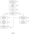
- FIG. 8 schematically illustrates a second example of a method for managing electrical consumption according to the invention.
- the process described in relation to the Fig. 6 has the sole purpose of avoiding damage to the safety fuse.
- the process described in relation to the Fig. 8 allows this same objective to be achieved. It also makes it possible, on the one hand, to lower the electrical energy consumption of gateway 1 in emergency mode, and on the other hand, to limit the disturbances suffered by each remote equipment associated with a BSS that must be deactivated.
- the process described in relation to the Fig. 6 is purely hardware and does not involve any software step
- the process described in relation to the Fig. 8 includes hardware steps and software steps.
- the hardware steps notably make it possible to instantly switch to emergency mode in the event of a mains power failure without damaging the safety fuse.
- steps 81 and 82 are strictly identical to steps 61 and 62 already explained.
- step 83 the processor 101 goes into standby mode for a delay of a predefined duration.
- the processor 101 checks in a step 84 whether the mains power supply has been restored. To do this, it checks the output value of the mains power outage detection module 111.
- step 84 the processor 101 determines that the mains power has not been restored, the processor 101 goes to a step 85.
- the processor 101 obtains information representative of Wi-Fi modules (and BSSs managed by these Wi-Fi modules) that can be cut and transmits a message comprising information representative of the BSSs concerned to associated remote equipment to these BSS.
- the information representative of Wi-Fi modules which can be cut indicates that the Wi-Fi module 1052 can be cut off. disabled.
- the processor 101 transmits to the remote equipment 2C information indicating that the BSS 3C will be stopped.
- the processor causes the power supply to each Wi-Fi module that can be cut off. To do this, it activates each lock associated with a power consumption reduction module 112 capable of cutting off the power supply to the Wi-Fi modules concerned.
- the power supply to each power amplifier of the 1052 Wi-Fi module is cut off. We then consider that the Wi-Fi 1052 module is cut off because without power amplification, its communication capabilities are very limited.
- step 87 the processor 101 regularly checks whether the mains power has been restored. When the processor determines that mains power has been restored, it proceeds to step 88 which we explain subsequently.
- step 84 the processor 101 determines that the mains power supply has been restored, the processor 101 implements step 88.
- each mains power outage detection module 111 instantly causes the reactivation of each hardware module cut during step 82.
- all circuits d The power supply opened during step 82 are closed.
- Wi-Fi modules and the BSS managed by these Wi-Fi modules deactivated during step 82 or during step 86 are reactivated.
- the Wi-Fi module 1052 which has been deactivated, is reactivated during step 88.
- the processor 101 causes a message transmission indicating to each remote device whose BSS has been deactivated that it has been reactivated.
- the processor 101 causes the transmission of a message to the remote equipment 2C indicating that the BSS 3C is reactivated.
- message communications are implemented between the gateway and at least one remote device concerned by the activation/deactivation of a Wi-Fi module in order to prevent this or these remote devices from the activation /deactivation of said Wi-Fi module.
- An advantage of the point-to-point approach is that it makes it possible to treat each remote device (respectively a group of remote devices) independently, all the remote devices not having the same capabilities (“capabilities” in Anglo-Saxon terminology) and therefore not supporting the same messages.
- a disadvantage of the point-to-point approach is that it induces an exchange of a large number of messages in order to address each remote device (respectively each group of remote devices), these latter (respectively the remote devices of the groups of remote devices) which can also respond according to the messages sent and thus increase the traffic.
- An advantage of the multicast approach is that we can minimize the number of messages to be sent.
- a disadvantage is that each message sent must be understood by each remote device concerned.
- the point-to-point approach uses BSS transition messages (“BSS Transition Management” in English terminology), subsequently called BTM messages, introduced by the IEEE 802.11v amendment.
- BSS Transition Management in English terminology
- BTM messages introduced by the IEEE 802.11v amendment.
- a Wi-Fi module supporting BTM messages knows if remote equipment also manages this type of message thanks to information obtained during each association request between the remote equipment and a BSS managed by said Wi-Fi module. Indeed, a “ BSS Transition Field” field is then positioned at “1” in an “ Extended Capabilities ” information element contained in the association request.
- a Wi-Fi module supporting BTM messages can send point-to-point BTM Request frames defined in the IEEE 802.11v amendment to each remote device that it wishes to inform of the deactivation of a BSS.
- BTM Request messages it is possible to inform remote equipment of the imminent deactivation of a BSS by setting a “ BSS Termination Included” information bit in a “ Request Mode ” field of said message.
- the Wi-Fi 1052 module manages BSS 3C.
- the Wi-Fi 1052 module transmits a BTM Request frame point-to-point to the remote equipment 2C in which the “ BSS Termination Included” information bit of the “ Request Mode ” field is positioned at “1”. This frame informs the 2C equipment that the 3C BSS will be deactivated.
- a Wi-Fi module supporting BTM messages can also indicate in BTMRequest frames a list indicating at least one BSS to migrate to.
- This list can be, for example, a predefined list or a list provided by the processor 101.
- This list includes a BSSID identifier (“BSS Identifier” in Anglo-Saxon terminology) for each BSS to which it is recommended to migrate with a priority associated.
- BSSID identifier (“BSS Identifier” in Anglo-Saxon terminology) for each BSS to which it is recommended to migrate with a priority associated.
- the Wi-Fi module 1052 transmits point-to-point to the remote equipment 2C a list of BSSs including the BSSID of the BSS 3A with maximum priority. Said list was for example provided to the Wi-Fi module 1052 by the processor 101.
- the remote equipment 2C can then attempt to connect to the BSS 3A.
- the Wi-Fi module 1050 transmits a point-to-point message to the equipment 2C informing it that the BSS 3C is restored.
- the Wi-Fi module 1050 has been informed by the processor 101 of the reactivation of the Wi-Fi module 1052.
- the Wi-Fi module 1050 uses for this a BTM Request frame including the BSSID of the BSS 3C.
- the “BSS Termination Included ” information bit in the “ Request Mode ” field is not set to “1”.
- the gateway 1 before switching off a Wi-Fi module, the gateway 1 creates a temporary BSS responsible for receiving the remote equipment associated with the BSS about to be deactivated.
- gateway 1 ie processor 101
- Each migrating equipment identifier can for example be a MAC address (“Medium Access control”: access control to the medium in English terminology) of the remote equipment concerned.
- the Wi-Fi module chosen by the gateway 1 can advantageously configure the temporary BSS so that its associated beacon (“beacon” in English terminology) does not broadcast its associated network name (service set identifier: “Service Set Identifier (SSID)” in Anglo-Saxon terminology) and have an open access policy in order to limit exchanges to the association procedure only (no authentication).
- this temporary BSS only responds to requests (“ Probe Request”, “ Association Request” messages, etc., as defined in the IEEE802.11 protocols) coming from remote equipment identified by the Wi-Fi module chosen by gateway 1 using the migrant equipment identifiers.
- Such an identification method allows you to avoid having to configure remote devices so that they are aware of this new temporary BSS.
- the Wi-Fi module intended to be deactivated transmits in its BTM Request frames the identifier of the temporary BSS managed by the Wi-Fi module chosen by gateway 1.
- the Wi-Fi module chosen by the gateway to manage the temporary BSS is the Wi-Fi module 1050.
- the gateway 1 informs the Wi-Fi module 1050 that it will have to create a temporary BSS and provides it with the identifier of the remote equipment 2C.
- the Wi-Fi module 1052 transmits to the remote equipment 2C a BTM Request frame including the identifier of the temporary BSS.
- the Wi-Fi module 1050 informed of the reactivation of the Wi-Fi module 1052 for example by the processor 101, transmits to the remote equipment 2C a BTM Request frame. informing of the imminent deactivation of the temporary BSS and inviting it to migrate either to its original BSS ( ie BSS 3C), or to another BSS such as BSS 3A.
- the temporary BSS is then deactivated by gateway 1 ( ie by processor 101).
- the remote equipment affected by a BSS shutdown does not support BTM messages.
- a de-association message is sent to the remote equipment concerned by the Wi-Fi module about to be deactivated. No more requests for information (“ Probe Request ”) or association requests (“ Association Request ”) are then managed by the Wi-Fi module intended to be deactivated.
- Probe Request requests for information
- Association Request association requests
- These saved identifiers can be used by the gateway 1 to allow an active Wi-Fi module of the gateway 1 to respond as a priority to requests for information/association emanating from remote equipment corresponding to these identifiers if they attempt to migrate to a BSS managed by said active Wi-Fi module of gateway 1.
- the Wi-Fi module 1052 transmits a de-association message from the BSS 3C to the remote equipment 2C and saves the identifier of remote equipment 2C. Following this de-association, when the remote equipment 2C attempts to associate with the BSS 3A, it is treated as a priority by the Wi-Fi module 1050.
- step 89 is not implemented by the processor 101.
- messages transmitted in multicast mode (“broadcast” in English terminology) are used. It is known that remote equipment whose BSS with which it is associated is deactivated, searches for a new BSS with which to associate (either passively by searching for beacons, or actively by sending messages). request for information Probe Request ). In order to help this remote device find a channel more quickly where a BSS is located on which it can migrate, it is possible for a Wi-Fi module that must be deactivated to announce a change of channel via an element CSA information (Channel Switch Announcement: “ Channel Switch Announcement” in English terminology) which can either be broadcast in a dedicated management frame, or in a beacon associated with the BSS with which said remote equipment is associated. In both cases, the CSA information element is broadcast in multicast mode.
- CSA information Channel Switch Announcement: “ Channel Switch Announcement” in English terminology
- the CSA information element indicates which channel the BSS is operating on to migrate to and when this channel change should take place. Positioning remote equipment on the channel on which the BSS to which it must migrate operates allows you to accelerate the migration. Indeed, the remote equipment, when searching for a new BSS, is likely to start with this channel in order to carry out operations necessary for recovering connectivity (passive search for beacons, Probe Request, etc.) . ..).
- the gateway can also save the identifiers of the remote equipment associated with the disabled Wi-Fi module (and the disabled BSS).
- the Wi-Fi module managing the BSS (existing or temporary as described above) to which the remote equipment is invited to migrate can then use these identifiers in order to respond as a priority to their request for information/association.
- the Wi-Fi module 1052 transmits a CSA information element indicating the channel on which the BSS 3A operates and when the channel change should take place in a beacon and in multicast mode.
- the 3C remote equipment receiving this beacon positions itself on the indicated channel and performs the necessary operations to search for connectivity in order to associate with the BSS 3A.
- a new element of information is introduced into a beacon in order to inform remote equipment of the deactivation of a BSS and to invite these remote equipment to migrate to another BSS (existing or temporary such as as described above) identified by its BSSID.
- This information element includes, for example, fields from the BTM Request frame such as the BSS termination, termination time and list of candidate BSS fields defined in the IEEE 802.11v amendment.
- BTM Request frames previously described as transmitted in a point-to-point mode are transmitted in multicast mode.
- the migrated remote devices can migrate back to their original BSS when the corresponding Wi-Fi module is restarted.
- An advantage of using a temporary BSS is that it is possible to minimize the number of messages to be transmitted to migrate all remote equipment that has migrated to the temporary BSS when the mains power is cut.
- the migration to the original BSS can be done in a controlled manner by sending the associated frame (either a BTM request frame, or a beacon containing the equivalent information element to the BTM Request frame) in multicast mode.
- the migration to the original BSS can be done in a controlled manner by sending the associated frame ( BTM Request ) in point-to-point mode. to each of these devices.
- BTM Request the associated frame
- the classic BSS end announcement is used by indicating in the tag the upcoming termination of said BSS temporary.
- the variant based on the CSA can also be implemented reciprocally.
- the migration to the original BSS must be done on a case-by-case basis so as not to also migrate the remote equipment which, before the mains power cut, was associated with the existing BSS.
- the point-to-point BTM Request or deassociation approaches are then used depending on the capabilities of the equipment to be migrated.
- a Wi-Fi module which creates a temporary BSS to accommodate remote equipment associated with a BSS intended to be deactivated, creates a new BSS unrelated to the deactivated BSS.
- the multicast approach is used each time a mains power outage is detected in order to minimize the number of message transmissions by gateway 1 (and therefore increase the autonomy of gateway 1)
- the point-to-point approach (respectively point-to-multipoint) can be favored when detecting a return of mains power, in order for example to first migrate the remote equipment that best responds to BTM messages.
- these remote devices can in fact be repatriated more easily due to their support for BTM messages.
Landscapes
- Engineering & Computer Science (AREA)
- Theoretical Computer Science (AREA)
- Physics & Mathematics (AREA)
- General Physics & Mathematics (AREA)
- General Engineering & Computer Science (AREA)
- Power Engineering (AREA)
- Computer Networks & Wireless Communication (AREA)
- Signal Processing (AREA)
- Automation & Control Theory (AREA)
- Computing Systems (AREA)
- Computer Hardware Design (AREA)
- Mobile Radio Communication Systems (AREA)
- Small-Scale Networks (AREA)
- Keying Circuit Devices (AREA)
- Organic Low-Molecular-Weight Compounds And Preparation Thereof (AREA)
- Stand-By Power Supply Arrangements (AREA)
- Direct Current Feeding And Distribution (AREA)
- Power Sources (AREA)
- Remote Monitoring And Control Of Power-Distribution Networks (AREA)
- Telephonic Communication Services (AREA)
Claims (12)
- Vorrichtung (1), die eine Batterie (14) umfasst, die durch eine Sicherung geschützt ist, die geeignet ist, einen maximalen Versorgungsstrom der Vorrichtung (1) über eine vorgegebene Dauer auszuhalten, wobei die Vorrichtung durch eine Netzversorgung (13) oder durch die Batterie (14) mit Strom versorgt werden kann, wobei die Versorgung durch die Batterie dazu bestimmt ist, die Netzversorgung bei Unterbrechung der Netzversorgung abzulösen, und ferner ein System (11) zur Stromverbrauchsverwaltung aufweist, wobei das System Folgendes umfasst:
ein Modul (111) zur Überwachung einer Eingangsspannung der Vorrichtung und zur Detektion einer Unterbrechung der Netzversorgung der Vorrichtung (1) und ein Modul (112) zur Unterbrechung der Versorgung von Hardwaremodulen, die in der Vorrichtung (1) enthalten sind, um den Stromverbrauch der Vorrichtung (1) zu verringern, wobei das System dadurch gekennzeichnet ist, dass:das Überwachungs- und Detektionsmodul (111) und das Versorgungsunterbrechungsmodul (112) von vollständig hardwarebasierten Modulen implementiert sind, unabhängig von jeglicher Interpretation von Maschinenanweisungen, und geeignet sind, in einer Zeit unter der vorgegebenen Dauer anzusprechen, während der die Sicherung den maximalen Versorgungsstrom aushalten kann, wobei es das Versorgungsunterbrechungsmodul (112) ermöglicht, eine vorgegebene Stromverbrauchsverringerung der Vorrichtung (1) zu erzielen, so dass die Vorrichtung (1) einen Versorgungsstrom verbraucht, der geringer als der maximale Versorgungsstrom ist, wobei das Versorgungsunterbrechungsmodul (112) vom Überwachungs- und Detektionsmodul (111) gesteuert wird, um eine Unterbrechung der Netzversorgung zu detektieren, und dazu ausgebildet ist, einen Stromversorgungskreis wenigstens eines vorgegebenen Hardwaremoduls zu öffnen, das in der Vorrichtung (1) enthalten ist, wenn eine Netzversorgungsunterbrechung detektiert ist,der Stromversorgungskreis eines Hardwaremoduls der Vorrichtung (1) nur dann vom Versorgungsunterbrechungsmodul (112) geöffnet werden kann, um den Stromverbrauch zu verringern, wenn sich ein Schloss (500), das diesem Hardwaremodul zugeordnet ist, in einem aktivierten Modus befindet, und nicht geöffnet werden kann, wenn sich das Schloss in einem deaktivierten Modus befindet, wobei jedes Schloss durch einen Prozessor (101) der Vorrichtung (1) unter Verwendung der Maschinenanweisungen im aktivierten oder deaktivierten Modus konfiguriert wird,so dass nach der Öffnung des Kreises zur Versorgung jedes Hardwaremoduls jedes vorgegebenen Hardwaremoduls gemäß der Konfiguration des Schlosses (500), wodurch die vorgegebene Stromverbrauchsverringerung der Vorrichtung (1) erzielt wird, der Prozessor (101) geeignet ist, die Öffnung des Stromversorgungskreises anderer Hardwaremodule (1052) der Vorrichtung (1) zu bewirken. - Vorrichtung nach Anspruch 1, dadurch gekennzeichnet, dass das Überwachungs- und Detektionsmodul (111) zum Detektieren einer Unterbrechung der Netzversorgung Mittel zum Vergleichen einer Spannung, die für eine Versorgungsspannung der Vorrichtung repräsentativ ist, mit einer vorgegebenen Referenzspannung umfasst, wobei eine Unterbrechung der Netzversorgung detektiert wird, wenn die vorgegebene Referenzspannung größer als die Spannung ist, die für die Versorgungsspannung der Vorrichtung repräsentativ ist.
- Verfahren zur Stromverbrauchsverwaltung in einer Vorrichtung (1) nach Anspruch 1, das die folgenden Schritte umfasst,
die vom Überwachungs- und Detektionsmodul (111) und vom Versorgungsunterbrechungsmodul (112) durchgeführt werden:Überwachen einer Eingangsversorgungsspannung der Vorrichtung (1) und Detektieren (61) einer Netzversorgungsunterbrechung;Öffnen eines Stromversorgungskreises wenigstens eines vorgegebenen Hardwaremoduls, das in der Vorrichtung (1) enthalten ist, wenn eine Netzversorgungsunterbrechung detektiert ist,wobei der Stromversorgungskreis eines Hardwaremoduls der Vorrichtung (1) nur dann vom Versorgungsunterbrechungsmodul (112) geöffnet werden kann, um den Stromverbrauch zu verringern, wenn sich ein Schloss (500), das diesem Hardwaremodul zugeordnet ist, in einem aktivierten Modus befindet, und nicht geöffnet werden kann, wenn sich das Schloss in einem deaktivierten Modus befindet, wobei jedes Schloss durch einen Prozessor (101) der Vorrichtung (1) unter Verwendung der Maschinenanweisungen im aktivierten oder deaktivierten Modus konfiguriert wird,so dass nach der Öffnung des Kreises zur Versorgung jedes Hardwaremoduls jedes vorgegebenen Hardwaremoduls gemäß der Konfiguration des Schlosses (500), wodurch die vorgegebene Stromverbrauchsverringerung der Vorrichtung (1) erzielt wird, der Prozessor (101) geeignet ist, die Öffnung des Stromversorgungskreises anderer Hardwaremodule (1050, 1051, 1052) der Vorrichtung (1) zu bewirken. - Verfahren nach Anspruch 3, dadurch gekennzeichnet, dass die anderen Hardwaremodule (1050, 1051, 1052) eine Mehrzahl von Drahtloskommunikationsmodulen (1050, 1051, 1052) umfassen, die jeweils wenigstens eine Drahtloskommunikationsverbindung (3A, 3B, 3C) verwalten, wobei jede Drahtlosverbindung wenigstens einem Remote-Gerät (2A, 2B, 2C) zugeordnet ist, wobei das Verfahren Folgendes umfasst: Überprüfen, ob die Netzversorgung der Vorrichtung (1) wiederhergestellt ist;
wenn die Netzversorgung nicht wiederhergestellt ist:Beziehen (85) einer Information, die für ein erstes Drahtloskommunikationsmodul (1052), das abgeschaltet werden kann, repräsentativ ist, und Übertragen (85), an jedes Remote-Gerät, das einer Drahtlosverbindung zugeordnet ist, die von dem ersten Drahtloskommunikationsmodul verwaltet wird, einer Nachricht, die eine Information umfasst, die für die Drahtlosverbindung repräsentativ ist;Unterbrechen (86) der Stromversorgung des ersten Drahtloskommunikationsmoduls; und,regelmäßiges Prüfen, ob die Netzversorgung wiederhergestellt wurde. - Verfahren nach Anspruch 4, dadurch gekennzeichnet, dass die Nachricht ferner eine Liste umfasst, die jedem Remote-Gerät, das einer Drahtlosverbindung zugeordnet ist, die von dem ersten Drahtloskommunikationsmodul verwaltet wird, wenigstens eine Drahtlosverbindung angibt, zu der migriert werden soll.
- Verfahren nach Anspruch 5, dadurch gekennzeichnet, dass die Drahtlosverbindung, zu der migriert werden soll, eine bestehende Drahtlosverbindung, die von einem zweiten Drahtloskommunikationsmodul verwaltet wird, oder eine temporäre Drahtlosverbindung ist, die von einem zweiten Drahtloskommunikationsmodul nach der Detektion der Netzversorgungsunterbrechung hergestellt wird.
- Verfahren nach Anspruch 6, dadurch gekennzeichnet, dass das Verfahren ferner Folgendes umfasst: Speichern einer Kennung jedes Remote-Geräts, das einer Drahtlosverbindung zugeordnet ist, die von dem ersten Drahtloskommunikationsmodul verwaltet wird; und Verwenden der gespeicherten Kennungen, um es einem zweiten Drahtloskommunikationsmodul (1050) zu ermöglichen, jedes Remote-Gerät, das von den Kennungen betroffen ist, mit Priorität zu behandeln, wenn diese versuchen, zu einer Drahtlosverbindung zu migrieren, die vom zweiten Drahtloskommunikationsmodul verwaltet wird.
- Verfahren nach einem der Ansprüche 4 bis 7, dadurch gekennzeichnet, dass, wenn die Netzversorgung wiederhergestellt ist, das Verfahren ferner Folgendes umfasst:Zulassen (88) der erneuten Stromversorgung jedes Hardwaremoduls der Vorrichtung (1), das bei der Detektion der Unterbrechung der Netzversorgung abgeschaltet wurde; und,Übertragen (89) einer Nachricht an jedes Remote-Gerät, das von der Stromversorgungsunterbrechung des ersten Drahtloskommunikationsmoduls betroffen ist, die angibt, dass jede Drahtlosverbindung, die von dem ersten Drahtloskommunikationsmodul verwaltet wird, reaktiviert wurde.
- Verfahren nach einem der Ansprüche 4 bis 8, dadurch gekennzeichnet, dass jede Nachricht gemäß einem Unicast-Kommunikationsmodus oder gemäß einem Multicast-Kommunikationsmodus oder gemäß einem Broadcast-Kommunikationsmodus an jedes Remote-Gerät übertragen wird, das von der Abschaltung des ersten Drahtloskommunikationsmoduls betroffen ist.
- Verfahren nach Anspruch 9, dadurch gekennzeichnet, dass der Broadcast-Kommunikationsmodus bei einer Detektion einer Netzversorgungsunterbrechung verwendet wird und der Unicast-Kommunikationsmodus oder der Multicast-Kommunikationsmodus bei einer Detektion einer Wiederherstellung der Netzversorgung verwendet wird.
- Computerprogramm, dadurch gekennzeichnet, dass es Anweisungen zur Durchführung der Schritte des Verfahrens nach einem der Ansprüche 3 bis 10 durch eine Vorrichtung (1) nach Anspruch 1 bei Ausführung des Programms durch den Prozessor (101) der Vorrichtung (1) umfasst.
- Speichermittel, dadurch gekennzeichnet, dass sie ein Computerprogramm speichern, das Anweisungen zur Durchführung der Schritte des Verfahrens nach einem der Ansprüche 3 bis 10 durch eine Vorrichtung (1) nach Anspruch 1 bei Ausführung des Programms durch den Prozessor (101) der Vorrichtung (1) umfasst.
Applications Claiming Priority (2)
| Application Number | Priority Date | Filing Date | Title |
|---|---|---|---|
| FR1661406A FR3059115B1 (fr) | 2016-11-23 | 2016-11-23 | Systeme de gestion de consommation electrique dans un appareil |
| PCT/EP2017/080000 WO2018095947A1 (fr) | 2016-11-23 | 2017-11-22 | Système de gestion de consommation électrique dans un appareil |
Publications (2)
| Publication Number | Publication Date |
|---|---|
| EP3545384A1 EP3545384A1 (de) | 2019-10-02 |
| EP3545384B1 true EP3545384B1 (de) | 2024-04-17 |
Family
ID=58455130
Family Applications (1)
| Application Number | Title | Priority Date | Filing Date |
|---|---|---|---|
| EP17822140.4A Active EP3545384B1 (de) | 2016-11-23 | 2017-11-22 | System zur verwaltung des stromverbrauchs in einer vorrichtung |
Country Status (6)
| Country | Link |
|---|---|
| US (1) | US10788802B2 (de) |
| EP (1) | EP3545384B1 (de) |
| CN (1) | CN109983422B (de) |
| CA (1) | CA3043448C (de) |
| FR (1) | FR3059115B1 (de) |
| WO (1) | WO2018095947A1 (de) |
Family Cites Families (14)
| Publication number | Priority date | Publication date | Assignee | Title |
|---|---|---|---|---|
| JP2000214966A (ja) * | 1999-01-20 | 2000-08-04 | Ricoh Co Ltd | 携帯型情報処理装置 |
| JP2006186852A (ja) * | 2004-12-28 | 2006-07-13 | Toshiba Corp | 無線通信機器及び無線通信基板 |
| JP2007323828A (ja) * | 2006-05-30 | 2007-12-13 | Hitachi Computer Peripherals Co Ltd | 電源設計方法 |
| US8907520B2 (en) * | 2007-03-14 | 2014-12-09 | Zonit Structured Solutions, Llc | Parallel redundant power distribution |
| JP5094301B2 (ja) * | 2007-09-19 | 2012-12-12 | 三洋電機株式会社 | パック電池の制御方法 |
| JP5646214B2 (ja) * | 2010-05-27 | 2014-12-24 | 三洋電機株式会社 | 電源装置 |
| CN102397624A (zh) * | 2010-09-17 | 2012-04-04 | 鼎迈医疗科技(苏州)有限公司 | 具有过流保护电路的植入式有源电子装置及电刺激系统 |
| US9015514B2 (en) * | 2012-08-28 | 2015-04-21 | Dell Products Lp. | Systems and methods for implementing persistent battery shutdown for information handling systems |
| CN104345654B (zh) * | 2013-07-29 | 2018-08-21 | 南京中兴新软件有限责任公司 | 不同功率整流器混插系统、及其节能实现方法和装置 |
| DE102013214726A1 (de) * | 2013-07-29 | 2015-01-29 | Bayerische Motoren Werke Aktiengesellschaft | Anordnung zur elektrischen Absicherung eines potentiellen Kurzschlusses bzw. einer Überlast in einem Gleichstromnetz mit systembedingten, variablem Quellinnenwiderstand |
| US9236909B2 (en) * | 2013-12-19 | 2016-01-12 | Stmicroelectronics, Inc. | Zero standby power for powerline communication devices |
| JP2016116110A (ja) * | 2014-12-16 | 2016-06-23 | 富士通株式会社 | 通信装置 |
| TWI531134B (zh) * | 2014-12-29 | 2016-04-21 | 廣達電腦股份有限公司 | 電池電源裝置 |
| US20160233555A1 (en) * | 2015-02-11 | 2016-08-11 | Physical Sciences, Inc. | Battery protection system and method |
-
2016
- 2016-11-23 FR FR1661406A patent/FR3059115B1/fr not_active Expired - Fee Related
-
2017
- 2017-11-22 CA CA3043448A patent/CA3043448C/en active Active
- 2017-11-22 CN CN201780072492.7A patent/CN109983422B/zh active Active
- 2017-11-22 WO PCT/EP2017/080000 patent/WO2018095947A1/fr not_active Ceased
- 2017-11-22 US US16/348,391 patent/US10788802B2/en active Active
- 2017-11-22 EP EP17822140.4A patent/EP3545384B1/de active Active
Also Published As
| Publication number | Publication date |
|---|---|
| FR3059115A1 (fr) | 2018-05-25 |
| CA3043448C (en) | 2021-07-06 |
| BR112019009493A8 (pt) | 2023-02-14 |
| FR3059115B1 (fr) | 2019-05-10 |
| CA3043448A1 (en) | 2018-05-31 |
| CN109983422B (zh) | 2023-05-30 |
| US20200057422A1 (en) | 2020-02-20 |
| US10788802B2 (en) | 2020-09-29 |
| BR112019009493A2 (pt) | 2019-07-30 |
| EP3545384A1 (de) | 2019-10-02 |
| CN109983422A (zh) | 2019-07-05 |
| WO2018095947A1 (fr) | 2018-05-31 |
Similar Documents
| Publication | Publication Date | Title |
|---|---|---|
| EP3122061B1 (de) | Übertragung von verschlüsselten daten von intelligenten stromzählern aus | |
| WO2013092796A1 (fr) | Procédé de routage au sein d'un terminal mobile émulant une carte de paiement sans contact | |
| BE1023200A1 (fr) | Connexions de réseau de données de paquet pour des dispositifs sans fil à priorités multiples | |
| EP2901771B1 (de) | Versetzung eines mit einem multilink-netzwerk verbundenen anlagenteils in einen standby-modus | |
| EP3078230B1 (de) | Vorrichtung und verfahren zum konfigurieren einer kommunikationsvorrichtung | |
| EP3809796B1 (de) | Standby- und reaktivierungsverfahren für zumindest teile eines drahtlosen kommunikationsnetzes und eines sammelknotens des netzes | |
| EP3053309A1 (de) | Verbesserte verwaltung von netzwerkverbindungen | |
| EP3545384A1 (de) | System zur verwaltung des stromverbrauchs in einer vorrichtung | |
| CN102811196B (zh) | 自动交换光网络中的网络安全保护方法、装置和系统 | |
| EP3747238B1 (de) | Aggregation mehrerer funkverbindungen in einem drahtlosen netzwerk | |
| EP2583429B1 (de) | Verfahren und system zur kommunikation auf der basis von ws-discovery | |
| EP4142240B1 (de) | Verfahren zur verwaltung einer controller-funktion durch ein gerät eines router-netzwerks | |
| EP3087785A1 (de) | Übertragungssystem mit erster und zweiter brückenvorrichtung | |
| EP3014518A1 (de) | Elektronische einheit für ein mobiles endgerät | |
| EP3085162B1 (de) | Funkkommunikationssystem mit vorrichtung zur zuordnung eines funkkommunikationsendgeräts zu einer funkkommunikationsstation, funkfunkkommunikationsstation, funkkommunikationsendgerät und zuordnungsverfahren | |
| WO2010061133A2 (fr) | Procede de configuration d'un circuit virtuel | |
| EP3211841B1 (de) | Verfahren zum entscheiden über die weiterleitung einer kopie einer wegermittlungsanfrage durch übertragung in einem kommunikationsnetz | |
| EP4327623A1 (de) | Verfahren und vorrichtung zur aktivierung von hostgeräte | |
| EP3122006B1 (de) | Verfahren zur auswahl einer elternknoten-vorrichtung in einem baumförmigen kommunikationsnetz | |
| EP4492735A1 (de) | Verfahren zur automatischen wiederherstellung der funktionalität in einem residential-gateway | |
| EP3797562A1 (de) | Verfahren zur verwaltung eines kommunikationskanals bei erkennen eines radarsignals | |
| FR2803151A1 (fr) | Procede et dispositif d'apprentissage automatique d'adresses dans un reseau de telecommunications, et systemes les mettant en oeuvre | |
| FR2782432A1 (fr) | Procede et dispositif de communication confidentielle sur un reseau | |
| FR2974961A1 (fr) | Procede de reveil d'une entite de communication multi bandes, dispositif et programme d'ordinateur correspondants |
Legal Events
| Date | Code | Title | Description |
|---|---|---|---|
| STAA | Information on the status of an ep patent application or granted ep patent |
Free format text: STATUS: UNKNOWN |
|
| STAA | Information on the status of an ep patent application or granted ep patent |
Free format text: STATUS: THE INTERNATIONAL PUBLICATION HAS BEEN MADE |
|
| PUAI | Public reference made under article 153(3) epc to a published international application that has entered the european phase |
Free format text: ORIGINAL CODE: 0009012 |
|
| STAA | Information on the status of an ep patent application or granted ep patent |
Free format text: STATUS: REQUEST FOR EXAMINATION WAS MADE |
|
| 17P | Request for examination filed |
Effective date: 20190613 |
|
| AK | Designated contracting states |
Kind code of ref document: A1 Designated state(s): AL AT BE BG CH CY CZ DE DK EE ES FI FR GB GR HR HU IE IS IT LI LT LU LV MC MK MT NL NO PL PT RO RS SE SI SK SM TR |
|
| AX | Request for extension of the european patent |
Extension state: BA ME |
|
| DAV | Request for validation of the european patent (deleted) | ||
| DAX | Request for extension of the european patent (deleted) | ||
| STAA | Information on the status of an ep patent application or granted ep patent |
Free format text: STATUS: EXAMINATION IS IN PROGRESS |
|
| 17Q | First examination report despatched |
Effective date: 20201026 |
|
| GRAP | Despatch of communication of intention to grant a patent |
Free format text: ORIGINAL CODE: EPIDOSNIGR1 |
|
| STAA | Information on the status of an ep patent application or granted ep patent |
Free format text: STATUS: GRANT OF PATENT IS INTENDED |
|
| INTG | Intention to grant announced |
Effective date: 20231113 |
|
| GRAS | Grant fee paid |
Free format text: ORIGINAL CODE: EPIDOSNIGR3 |
|
| RAP3 | Party data changed (applicant data changed or rights of an application transferred) |
Owner name: SAGEMCOM BROADBAND SAS |
|
| GRAA | (expected) grant |
Free format text: ORIGINAL CODE: 0009210 |
|
| STAA | Information on the status of an ep patent application or granted ep patent |
Free format text: STATUS: THE PATENT HAS BEEN GRANTED |
|
| AK | Designated contracting states |
Kind code of ref document: B1 Designated state(s): AL AT BE BG CH CY CZ DE DK EE ES FI FR GB GR HR HU IE IS IT LI LT LU LV MC MK MT NL NO PL PT RO RS SE SI SK SM TR |
|
| REG | Reference to a national code |
Ref country code: GB Ref legal event code: FG4D Free format text: NOT ENGLISH |
|
| REG | Reference to a national code |
Ref country code: CH Ref legal event code: EP |
|
| REG | Reference to a national code |
Ref country code: DE Ref legal event code: R096 Ref document number: 602017081124 Country of ref document: DE |
|
| REG | Reference to a national code |
Ref country code: IE Ref legal event code: FG4D Free format text: LANGUAGE OF EP DOCUMENT: FRENCH |
|
| REG | Reference to a national code |
Ref country code: LT Ref legal event code: MG9D |
|
| REG | Reference to a national code |
Ref country code: NL Ref legal event code: MP Effective date: 20240417 |
|
| REG | Reference to a national code |
Ref country code: AT Ref legal event code: MK05 Ref document number: 1677860 Country of ref document: AT Kind code of ref document: T Effective date: 20240417 |
|
| PG25 | Lapsed in a contracting state [announced via postgrant information from national office to epo] |
Ref country code: NL Free format text: LAPSE BECAUSE OF FAILURE TO SUBMIT A TRANSLATION OF THE DESCRIPTION OR TO PAY THE FEE WITHIN THE PRESCRIBED TIME-LIMIT Effective date: 20240417 |
|
| PG25 | Lapsed in a contracting state [announced via postgrant information from national office to epo] |
Ref country code: NL Free format text: LAPSE BECAUSE OF FAILURE TO SUBMIT A TRANSLATION OF THE DESCRIPTION OR TO PAY THE FEE WITHIN THE PRESCRIBED TIME-LIMIT Effective date: 20240417 |
|
| PG25 | Lapsed in a contracting state [announced via postgrant information from national office to epo] |
Ref country code: IS Free format text: LAPSE BECAUSE OF FAILURE TO SUBMIT A TRANSLATION OF THE DESCRIPTION OR TO PAY THE FEE WITHIN THE PRESCRIBED TIME-LIMIT Effective date: 20240817 |
|
| PG25 | Lapsed in a contracting state [announced via postgrant information from national office to epo] |
Ref country code: BG Free format text: LAPSE BECAUSE OF FAILURE TO SUBMIT A TRANSLATION OF THE DESCRIPTION OR TO PAY THE FEE WITHIN THE PRESCRIBED TIME-LIMIT Effective date: 20240417 |
|
| PG25 | Lapsed in a contracting state [announced via postgrant information from national office to epo] |
Ref country code: HR Free format text: LAPSE BECAUSE OF FAILURE TO SUBMIT A TRANSLATION OF THE DESCRIPTION OR TO PAY THE FEE WITHIN THE PRESCRIBED TIME-LIMIT Effective date: 20240417 Ref country code: FI Free format text: LAPSE BECAUSE OF FAILURE TO SUBMIT A TRANSLATION OF THE DESCRIPTION OR TO PAY THE FEE WITHIN THE PRESCRIBED TIME-LIMIT Effective date: 20240417 |
|
| PG25 | Lapsed in a contracting state [announced via postgrant information from national office to epo] |
Ref country code: GR Free format text: LAPSE BECAUSE OF FAILURE TO SUBMIT A TRANSLATION OF THE DESCRIPTION OR TO PAY THE FEE WITHIN THE PRESCRIBED TIME-LIMIT Effective date: 20240718 |
|
| PG25 | Lapsed in a contracting state [announced via postgrant information from national office to epo] |
Ref country code: PT Free format text: LAPSE BECAUSE OF FAILURE TO SUBMIT A TRANSLATION OF THE DESCRIPTION OR TO PAY THE FEE WITHIN THE PRESCRIBED TIME-LIMIT Effective date: 20240819 |
|
| PG25 | Lapsed in a contracting state [announced via postgrant information from national office to epo] |
Ref country code: ES Free format text: LAPSE BECAUSE OF FAILURE TO SUBMIT A TRANSLATION OF THE DESCRIPTION OR TO PAY THE FEE WITHIN THE PRESCRIBED TIME-LIMIT Effective date: 20240417 |
|
| PG25 | Lapsed in a contracting state [announced via postgrant information from national office to epo] |
Ref country code: AT Free format text: LAPSE BECAUSE OF FAILURE TO SUBMIT A TRANSLATION OF THE DESCRIPTION OR TO PAY THE FEE WITHIN THE PRESCRIBED TIME-LIMIT Effective date: 20240417 |
|
| PG25 | Lapsed in a contracting state [announced via postgrant information from national office to epo] |
Ref country code: PL Free format text: LAPSE BECAUSE OF FAILURE TO SUBMIT A TRANSLATION OF THE DESCRIPTION OR TO PAY THE FEE WITHIN THE PRESCRIBED TIME-LIMIT Effective date: 20240417 |
|
| PG25 | Lapsed in a contracting state [announced via postgrant information from national office to epo] |
Ref country code: LV Free format text: LAPSE BECAUSE OF FAILURE TO SUBMIT A TRANSLATION OF THE DESCRIPTION OR TO PAY THE FEE WITHIN THE PRESCRIBED TIME-LIMIT Effective date: 20240417 |
|
| PG25 | Lapsed in a contracting state [announced via postgrant information from national office to epo] |
Ref country code: PT Free format text: LAPSE BECAUSE OF FAILURE TO SUBMIT A TRANSLATION OF THE DESCRIPTION OR TO PAY THE FEE WITHIN THE PRESCRIBED TIME-LIMIT Effective date: 20240819 Ref country code: PL Free format text: LAPSE BECAUSE OF FAILURE TO SUBMIT A TRANSLATION OF THE DESCRIPTION OR TO PAY THE FEE WITHIN THE PRESCRIBED TIME-LIMIT Effective date: 20240417 Ref country code: NO Free format text: LAPSE BECAUSE OF FAILURE TO SUBMIT A TRANSLATION OF THE DESCRIPTION OR TO PAY THE FEE WITHIN THE PRESCRIBED TIME-LIMIT Effective date: 20240717 Ref country code: LV Free format text: LAPSE BECAUSE OF FAILURE TO SUBMIT A TRANSLATION OF THE DESCRIPTION OR TO PAY THE FEE WITHIN THE PRESCRIBED TIME-LIMIT Effective date: 20240417 Ref country code: IS Free format text: LAPSE BECAUSE OF FAILURE TO SUBMIT A TRANSLATION OF THE DESCRIPTION OR TO PAY THE FEE WITHIN THE PRESCRIBED TIME-LIMIT Effective date: 20240817 Ref country code: HR Free format text: LAPSE BECAUSE OF FAILURE TO SUBMIT A TRANSLATION OF THE DESCRIPTION OR TO PAY THE FEE WITHIN THE PRESCRIBED TIME-LIMIT Effective date: 20240417 Ref country code: GR Free format text: LAPSE BECAUSE OF FAILURE TO SUBMIT A TRANSLATION OF THE DESCRIPTION OR TO PAY THE FEE WITHIN THE PRESCRIBED TIME-LIMIT Effective date: 20240718 Ref country code: FI Free format text: LAPSE BECAUSE OF FAILURE TO SUBMIT A TRANSLATION OF THE DESCRIPTION OR TO PAY THE FEE WITHIN THE PRESCRIBED TIME-LIMIT Effective date: 20240417 Ref country code: ES Free format text: LAPSE BECAUSE OF FAILURE TO SUBMIT A TRANSLATION OF THE DESCRIPTION OR TO PAY THE FEE WITHIN THE PRESCRIBED TIME-LIMIT Effective date: 20240417 Ref country code: BG Free format text: LAPSE BECAUSE OF FAILURE TO SUBMIT A TRANSLATION OF THE DESCRIPTION OR TO PAY THE FEE WITHIN THE PRESCRIBED TIME-LIMIT Effective date: 20240417 Ref country code: AT Free format text: LAPSE BECAUSE OF FAILURE TO SUBMIT A TRANSLATION OF THE DESCRIPTION OR TO PAY THE FEE WITHIN THE PRESCRIBED TIME-LIMIT Effective date: 20240417 Ref country code: RS Free format text: LAPSE BECAUSE OF FAILURE TO SUBMIT A TRANSLATION OF THE DESCRIPTION OR TO PAY THE FEE WITHIN THE PRESCRIBED TIME-LIMIT Effective date: 20240717 |
|
| PG25 | Lapsed in a contracting state [announced via postgrant information from national office to epo] |
Ref country code: DK Free format text: LAPSE BECAUSE OF FAILURE TO SUBMIT A TRANSLATION OF THE DESCRIPTION OR TO PAY THE FEE WITHIN THE PRESCRIBED TIME-LIMIT Effective date: 20240417 |
|
| REG | Reference to a national code |
Ref country code: DE Ref legal event code: R097 Ref document number: 602017081124 Country of ref document: DE |
|
| PG25 | Lapsed in a contracting state [announced via postgrant information from national office to epo] |
Ref country code: EE Free format text: LAPSE BECAUSE OF FAILURE TO SUBMIT A TRANSLATION OF THE DESCRIPTION OR TO PAY THE FEE WITHIN THE PRESCRIBED TIME-LIMIT Effective date: 20240417 |
|
| PG25 | Lapsed in a contracting state [announced via postgrant information from national office to epo] |
Ref country code: CZ Free format text: LAPSE BECAUSE OF FAILURE TO SUBMIT A TRANSLATION OF THE DESCRIPTION OR TO PAY THE FEE WITHIN THE PRESCRIBED TIME-LIMIT Effective date: 20240417 |
|
| PG25 | Lapsed in a contracting state [announced via postgrant information from national office to epo] |
Ref country code: SK Free format text: LAPSE BECAUSE OF FAILURE TO SUBMIT A TRANSLATION OF THE DESCRIPTION OR TO PAY THE FEE WITHIN THE PRESCRIBED TIME-LIMIT Effective date: 20240417 Ref country code: RO Free format text: LAPSE BECAUSE OF FAILURE TO SUBMIT A TRANSLATION OF THE DESCRIPTION OR TO PAY THE FEE WITHIN THE PRESCRIBED TIME-LIMIT Effective date: 20240417 |
|
| PG25 | Lapsed in a contracting state [announced via postgrant information from national office to epo] |
Ref country code: SM Free format text: LAPSE BECAUSE OF FAILURE TO SUBMIT A TRANSLATION OF THE DESCRIPTION OR TO PAY THE FEE WITHIN THE PRESCRIBED TIME-LIMIT Effective date: 20240417 |
|
| PG25 | Lapsed in a contracting state [announced via postgrant information from national office to epo] |
Ref country code: SM Free format text: LAPSE BECAUSE OF FAILURE TO SUBMIT A TRANSLATION OF THE DESCRIPTION OR TO PAY THE FEE WITHIN THE PRESCRIBED TIME-LIMIT Effective date: 20240417 Ref country code: SK Free format text: LAPSE BECAUSE OF FAILURE TO SUBMIT A TRANSLATION OF THE DESCRIPTION OR TO PAY THE FEE WITHIN THE PRESCRIBED TIME-LIMIT Effective date: 20240417 Ref country code: RO Free format text: LAPSE BECAUSE OF FAILURE TO SUBMIT A TRANSLATION OF THE DESCRIPTION OR TO PAY THE FEE WITHIN THE PRESCRIBED TIME-LIMIT Effective date: 20240417 Ref country code: EE Free format text: LAPSE BECAUSE OF FAILURE TO SUBMIT A TRANSLATION OF THE DESCRIPTION OR TO PAY THE FEE WITHIN THE PRESCRIBED TIME-LIMIT Effective date: 20240417 Ref country code: DK Free format text: LAPSE BECAUSE OF FAILURE TO SUBMIT A TRANSLATION OF THE DESCRIPTION OR TO PAY THE FEE WITHIN THE PRESCRIBED TIME-LIMIT Effective date: 20240417 Ref country code: CZ Free format text: LAPSE BECAUSE OF FAILURE TO SUBMIT A TRANSLATION OF THE DESCRIPTION OR TO PAY THE FEE WITHIN THE PRESCRIBED TIME-LIMIT Effective date: 20240417 |
|
| PG25 | Lapsed in a contracting state [announced via postgrant information from national office to epo] |
Ref country code: IT Free format text: LAPSE BECAUSE OF FAILURE TO SUBMIT A TRANSLATION OF THE DESCRIPTION OR TO PAY THE FEE WITHIN THE PRESCRIBED TIME-LIMIT Effective date: 20240417 |
|
| PLBE | No opposition filed within time limit |
Free format text: ORIGINAL CODE: 0009261 |
|
| STAA | Information on the status of an ep patent application or granted ep patent |
Free format text: STATUS: NO OPPOSITION FILED WITHIN TIME LIMIT |
|
| 26N | No opposition filed |
Effective date: 20250120 |
|
| PG25 | Lapsed in a contracting state [announced via postgrant information from national office to epo] |
Ref country code: SI Free format text: LAPSE BECAUSE OF FAILURE TO SUBMIT A TRANSLATION OF THE DESCRIPTION OR TO PAY THE FEE WITHIN THE PRESCRIBED TIME-LIMIT Effective date: 20240417 |
|
| REG | Reference to a national code |
Ref country code: CH Ref legal event code: PL |
|
| PG25 | Lapsed in a contracting state [announced via postgrant information from national office to epo] |
Ref country code: MC Free format text: LAPSE BECAUSE OF FAILURE TO SUBMIT A TRANSLATION OF THE DESCRIPTION OR TO PAY THE FEE WITHIN THE PRESCRIBED TIME-LIMIT Effective date: 20240417 |
|
| PG25 | Lapsed in a contracting state [announced via postgrant information from national office to epo] |
Ref country code: LU Free format text: LAPSE BECAUSE OF NON-PAYMENT OF DUE FEES Effective date: 20241122 |
|
| REG | Reference to a national code |
Ref country code: CH Ref legal event code: PL |
|
| PG25 | Lapsed in a contracting state [announced via postgrant information from national office to epo] |
Ref country code: CH Free format text: LAPSE BECAUSE OF NON-PAYMENT OF DUE FEES Effective date: 20241130 |
|
| REG | Reference to a national code |
Ref country code: BE Ref legal event code: MM Effective date: 20241130 |
|
| PG25 | Lapsed in a contracting state [announced via postgrant information from national office to epo] |
Ref country code: SE Free format text: LAPSE BECAUSE OF FAILURE TO SUBMIT A TRANSLATION OF THE DESCRIPTION OR TO PAY THE FEE WITHIN THE PRESCRIBED TIME-LIMIT Effective date: 20240417 |
|
| PG25 | Lapsed in a contracting state [announced via postgrant information from national office to epo] |
Ref country code: BE Free format text: LAPSE BECAUSE OF NON-PAYMENT OF DUE FEES Effective date: 20241130 |
|
| PG25 | Lapsed in a contracting state [announced via postgrant information from national office to epo] |
Ref country code: IE Free format text: LAPSE BECAUSE OF NON-PAYMENT OF DUE FEES Effective date: 20241122 |
|
| PGFP | Annual fee paid to national office [announced via postgrant information from national office to epo] |
Ref country code: DE Payment date: 20251022 Year of fee payment: 9 |
|
| PGFP | Annual fee paid to national office [announced via postgrant information from national office to epo] |
Ref country code: GB Payment date: 20251022 Year of fee payment: 9 |
|
| PGFP | Annual fee paid to national office [announced via postgrant information from national office to epo] |
Ref country code: FR Payment date: 20251022 Year of fee payment: 9 |
|
| PG25 | Lapsed in a contracting state [announced via postgrant information from national office to epo] |
Ref country code: HU Free format text: LAPSE BECAUSE OF FAILURE TO SUBMIT A TRANSLATION OF THE DESCRIPTION OR TO PAY THE FEE WITHIN THE PRESCRIBED TIME-LIMIT; INVALID AB INITIO Effective date: 20171122 |
|
| PG25 | Lapsed in a contracting state [announced via postgrant information from national office to epo] |
Ref country code: CY Free format text: LAPSE BECAUSE OF FAILURE TO SUBMIT A TRANSLATION OF THE DESCRIPTION OR TO PAY THE FEE WITHIN THE PRESCRIBED TIME-LIMIT; INVALID AB INITIO Effective date: 20171122 |
|
| PG25 | Lapsed in a contracting state [announced via postgrant information from national office to epo] |
Ref country code: TR Free format text: LAPSE BECAUSE OF FAILURE TO SUBMIT A TRANSLATION OF THE DESCRIPTION OR TO PAY THE FEE WITHIN THE PRESCRIBED TIME-LIMIT Effective date: 20240417 |
|
| PG25 | Lapsed in a contracting state [announced via postgrant information from national office to epo] |
Ref country code: LT Free format text: LAPSE BECAUSE OF FAILURE TO SUBMIT A TRANSLATION OF THE DESCRIPTION OR TO PAY THE FEE WITHIN THE PRESCRIBED TIME-LIMIT Effective date: 20240417 |