EP4142240B1 - Verfahren zur verwaltung einer controller-funktion durch ein gerät eines router-netzwerks - Google Patents
Verfahren zur verwaltung einer controller-funktion durch ein gerät eines router-netzwerks Download PDFInfo
- Publication number
- EP4142240B1 EP4142240B1 EP22191142.3A EP22191142A EP4142240B1 EP 4142240 B1 EP4142240 B1 EP 4142240B1 EP 22191142 A EP22191142 A EP 22191142A EP 4142240 B1 EP4142240 B1 EP 4142240B1
- Authority
- EP
- European Patent Office
- Prior art keywords
- equipment
- controller
- investigator
- role
- discovery request
- Prior art date
- Legal status (The legal status is an assumption and is not a legal conclusion. Google has not performed a legal analysis and makes no representation as to the accuracy of the status listed.)
- Active
Links
Images



Classifications
-
- H—ELECTRICITY
- H04—ELECTRIC COMMUNICATION TECHNIQUE
- H04L—TRANSMISSION OF DIGITAL INFORMATION, e.g. TELEGRAPHIC COMMUNICATION
- H04L41/00—Arrangements for maintenance, administration or management of data switching networks, e.g. of packet switching networks
- H04L41/12—Discovery or management of network topologies
-
- H—ELECTRICITY
- H04—ELECTRIC COMMUNICATION TECHNIQUE
- H04L—TRANSMISSION OF DIGITAL INFORMATION, e.g. TELEGRAPHIC COMMUNICATION
- H04L41/00—Arrangements for maintenance, administration or management of data switching networks, e.g. of packet switching networks
- H04L41/30—Decision processes by autonomous network management units using voting and bidding
-
- H—ELECTRICITY
- H04—ELECTRIC COMMUNICATION TECHNIQUE
- H04L—TRANSMISSION OF DIGITAL INFORMATION, e.g. TELEGRAPHIC COMMUNICATION
- H04L63/00—Network architectures or network communication protocols for network security
- H04L63/14—Network architectures or network communication protocols for network security for detecting or protecting against malicious traffic
- H04L63/1408—Network architectures or network communication protocols for network security for detecting or protecting against malicious traffic by monitoring network traffic
- H04L63/1416—Event detection, e.g. attack signature detection
-
- H—ELECTRICITY
- H04—ELECTRIC COMMUNICATION TECHNIQUE
- H04W—WIRELESS COMMUNICATION NETWORKS
- H04W84/00—Network topologies
- H04W84/02—Hierarchically pre-organised networks, e.g. paging networks, cellular networks, WLAN [Wireless Local Area Network] or WLL [Wireless Local Loop]
- H04W84/10—Small scale networks; Flat hierarchical networks
- H04W84/12—WLAN [Wireless Local Area Networks]
-
- H—ELECTRICITY
- H04—ELECTRIC COMMUNICATION TECHNIQUE
- H04W—WIRELESS COMMUNICATION NETWORKS
- H04W84/00—Network topologies
- H04W84/18—Self-organising networks, e.g. ad-hoc networks or sensor networks
- H04W84/20—Leader-follower arrangements
Definitions
- a wireless network can be extended geographically through the use of multiple devices or access points interconnected by a routing network and emitting a unified wireless network.
- the management of such a routing network is defined by the Wi-Fi Alliance's EasyMesh standard.
- the EasyMesh standard at least one device in the routing network has a controller function.
- the controller function of said device When the controller function of said device is active, the device assumes a controller role within the routing network and is then responsible for managing the routing network.
- a device that does not assume the controller role for example a device whose controller function is inactive or a device that does not have the controller function, assumes an agent role.
- a device that assumes the controller role can also simultaneously assume the agent role.
- the EasyMesh standard does not define a method for selecting one of the devices to actually perform the controller role.
- a first solution is to configure each device with the controller function so that the device starts up by assuming the agent role.
- An election process is then implemented through a user action to select the device assuming the controller role.
- Such an action involves, for example, connecting an Ethernet cable or manual configuration.
- such an election process is dependent on user action.
- Such an election method is based on the use of predefined selection criteria.
- the use of such criteria may result, when the configuration of the routing network evolves, in a device initially ensuring the role of controller being replaced by another device in the routing network to ensure the role of controller even though the device initially ensuring the role of controller remains in the routing network.
- the document EP 3 267 623 A2 Describes a management protocol used by access points on a local area network (LAN) to confirm that one of the access points is designated as the master access point, responsible for allocating IP addresses to devices joining the LAN. Access points on the LAN can reconfirm the master access point through the management protocol when the LAN topology changes.
- LAN local area network
- the management method allows a single device to be selected to act as a controller when a management conflict arises resulting from two devices acting as controllers.
- the management method does not require any external action such as user intervention.
- the management method prioritizes the retention of the controller role by the equipment that has been performing said controller role for the longest time.
- the management method thus limits the presence of disruptions in the organization of the routing network during a configuration change.
- the method further comprises transmitting in the routing network a configuration change message when the investigating equipment deactivates the controller function, the configuration change message comprising an identifier of the responding equipment ensuring the role of controller so that each other equipment can send said responding equipment a configuration renewal request.
- the management method makes it possible to select equipment to ensure the role of controller when a change in the configuration of the routing network results in the absence of equipment ensuring said role of controller.
- the investigating equipment checks at regular intervals that the role of controller C is ensured by a single equipment in the routing network and can activate and deactivate its controller function dynamically, in other words taking into account the temporal evolution of the configuration of the routing network.
- the invention also relates to a routing network in which the above-mentioned method is implemented, in any of its embodiments, by each equipment provided with the dynamic control service of the routing network.
- the invention also relates to a computer program, which can be stored on a medium and/or downloaded from a communication network, in order to be read by a processor.
- This computer program comprises instructions for implementing the above-mentioned method in any of its embodiments, when said program is executed by the processor.
- the invention also relates to an information storage medium storing such a computer program.
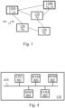
- FIG. 1 thus schematically illustrates a routing network 100, in a first configuration, comprising at least one piece of equipment 110A, 110B, provided with a dynamic control service cd.
- Each routing network 100 is a communication network intended to interconnect several devices also called access points, in order to provide a unified wireless network.
- Each device of said routing network 100 is capable of managing a wireless network having characteristics of the unified wireless network such as an identifier such as for example the SSID (for "Service Set IDentifier" in English) of the unified wireless network and a password, which makes it possible for example to geographically extend the coverage of said unified wireless network.
- the management of the routing network 100 is defined for example by the EasyMesh standard, or by other solutions for managing the meshing of Wi-Fi equipment to form a meshed and unified wireless network.
- At least one device of the routing network 100 comprises a controller function, said controller function being able to be active or inactive.
- the controller function of a device When the controller function of a device is active, the device assumes a controller role C within the routing network and is then responsible for managing the routing network. Any device whose controller function is inactive or does not have a controller function assumes an agent role Ag. A device assuming the controller role can also simultaneously assume the agent role.
- a single device of each routing network 100 must ensure the role of controller C when said routing network is in a permanent regime, in other words as long as the routing network 100 does not undergo a structural modification resulting from an addition or a deletion of at least one device or a modification of the role ensured by a device.
- the routing network 100 thus comprises the equipment 110A which ensures the role of controller C and further comprises the equipment 110B and equipment 120 which ensures the role of agent Ag.
- the devices 110A and 110B are provided with a dynamic controller service.
- Each device 110A, 110B provided with the dynamic controller service has the ability to activate and deactivate the controller function in order to ensure or not the role of controller C.
- the activation and deactivation of the controller function does not require restarting the device.
- a management component capable of activating or deactivating a software brick implementing the controller function is for example used to activate or deactivate the controller function without requiring a restart.
- FIG. 2 schematically illustrates a method for managing the controller function of a device 110A, 110B provided with the dynamic controller service, called investigator device 110. Said management method is intended to activate and deactivate the controller function of the investigator device.
- the investigating equipment determines and records its age at the present time.
- the age of an equipment provided with a dynamic control service cd is a duration, determined at a given time, since which the controller function of the equipment is active. If the controller function of an equipment is inactive, the age of said equipment is zero.
- the investigating equipment broadcasts, in the routing network 100, an initial discovery request RQ_DECOUV intended to identify any equipment of the routing network 100 which provides the controller function and to identify any equipment of the routing network 100 which is provided with the control service dynamic.
- the initial discovery request RQ DECOUV is issued as soon as the age of the investigator equipment is recorded.
- An initial discovery request RQ_DECOUV includes information representative of the controller role C, indicating a search in the routing network 100 for any equipment providing the controller role C, and includes information representative of the dynamic control service cd, indicating a search in the routing network 100 for any equipment provided with the dynamic control service cd.
- the initial discovery request RQ_DECOUV complies with a message format defined by the IEEE1905.1 standard and comprises TLV (for "Type Length Value") format fields.
- the initial discovery request RQ_DECOUV of the investigating equipment thus comprises a first TLV format field comprising the value 0x01, the value 0x01 being representative of the controller role C, and comprises a second TLV format field comprising the value 0x02, the value 0x02 being representative of the dynamic control service cd.
- the use of the standardized message format defined by the IEEE1905.1 standard and comprising TLV format fields thus makes it possible to guarantee the compatibility of the management method with the EasyMesh standard or with other solutions for managing a mesh wireless network.
- the investigator equipment determines whether its controller function is active at the time of broadcasting the discovery request RQ_DECOUV. If this is the case, a step 204 is performed. Otherwise, the investigator equipment considers that its controller function is inactive, in other words that it is performing the role of agent Ag, and performs a step 300.
- step 204 the investigating equipment determines whether a REP response to the initial discovery request RQ_DECOUV is received from another equipment, called responding equipment, of the routing network 100. If a REP response is received, a step 205 is performed. Otherwise, a step 220 is performed.
- the investigator equipment determines whether a first predefined time limit has elapsed.
- the first predefined time limit is counted from the broadcast of the previous discovery request which corresponds to the initial discovery request RQ_DECOUV broadcast by the investigator equipment in the previous step 201.
- the first predefined time limit is less than or equal to 60 seconds. If the first predefined time limit has elapsed, the investigator equipment returns to step 201. Thus, the management method is implemented by the investigator equipment at regular intervals. Otherwise, the investigator equipment returns to step 204.
- step 205 the investigating equipment analyzes the REP response to determine whether the responding equipment is performing the role of controller C.
- Step 220 is then carried out.
- step 206 the investigating equipment analyzes the REP response in order to determine whether the responding equipment is provided with the dynamic control service cd.
- the investigating equipment determines that the responding equipment is provided with the dynamic control service cd.
- a step 207 is then carried out.
- the investigating equipment determines that the responding equipment is not provided with the dynamic control service cd.
- a step 208 is then carried out. The interoperability of the management method with equipment lacking the dynamic control service and therefore not implementing said management method is thus guaranteed.
- the investigating equipment obtains the age of the responding equipment in the received REP response.
- any REP response from a responding equipment comprising information representative of the dynamic control service cd also comprises information representative of the age of said responding equipment.
- the REP response in the case where the REP response from the responding equipment complies with the format defined by the IEEE 1905.1 standard, the REP response then includes a TLV format field, called the "age" field, including an identifier representing an age type and a variable representing the age of the responding equipment.
- the investigating equipment further compares its own age with the age of the responding equipment. If the age of the investigating equipment is less than the age of the responding equipment, the investigating equipment performs step 208. Otherwise, step 220 is performed.
- the management method thus prioritizes the retention of the controller role by the equipment that has been performing said controller role for the longest time. The management method thus limits the presence of disruptions in the organization of the routing network during a configuration change.
- step 208 the investigating equipment decides to deactivate its controller function.
- the responding equipment is then considered to be the only equipment ensuring the role of controller C in the routing network 100.
- the management method thus makes it possible to select a single equipment ensuring the role of controller C in the routing network without requiring external action such as user intervention.
- the investigator equipment waits for the first predefined time to elapse.
- the investigator equipment returns to step 201.
- the investigator equipment checks at regular intervals that the controller role C is performed by a single equipment in the routing network and can activate and deactivate its controller function dynamically, in other words by taking into account the temporal evolution of the configuration of the routing network.
- the investigator equipment performs a succession of steps described in the Fig. 3
- the investigator equipment then returns to step 201.
- FIG. 3A schematically illustrates step 300 of the management method according to a first embodiment. Step 300 is performed following step 203 when the controller function of the investigator equipment is inactive at the time of broadcasting the initial discovery request RQ_DECOUV.
- a counter c 0 .
- step 303 similar to step 205, the investigating equipment determines whether the responding equipment is performing the role of controller C. If the investigating equipment detects, in the REP response sent by the responding equipment, the presence of information representative of the role of controller C, such as the field comprising the value 0x00, the investigating equipment determines that the responding equipment is performing the role of controller C and performs a step 310. Otherwise, step 304 is performed.
- step 310 similar to step 210, the investigator equipment waits for the first predefined time to elapse. When the first predefined time has elapsed, the investigator equipment returns to step 201.
- step 306 the investigator equipment broadcasts an additional discovery request RQ_DECOUV_B, identical to the initial discovery request RQ_DECOUV previously issued in step 201.
- step 308 the investigator equipment considers that no other equipment present in the routing network 100 is performing the role of controller C.
- the investigator equipment decides to activate its controller function.
- the investigator equipment then performs step 210 described in Fig. 2 then returns to step 201 described in Fig. 2 .
- the investigating equipment determines whether a REP response to the initial discovery request RQ_DECOUV or to an additional discovery request RQ_DECOUV_B is received from another equipment, called responding equipment, of the routing network 100. If a REP response is received, a step 313 is performed. Otherwise, a step 314 is performed.
- step 310 similar to step 210, the investigator equipment waits for the first predefined time to elapse. When the first predefined time has elapsed, the investigator equipment returns to step 201.
- step 314 the investigator equipment determines whether a second predefined time limit has elapsed.
- the second predefined time limit is counted from the broadcast of the initial discovery request RQ_DECOUV, issued in the previous step 201. If the second predefined time limit has elapsed, step 308 is performed. Otherwise, the investigator equipment performs a step 315.
- the second predefined time limit is greater than the first predefined time limit.
- step 315 the investigator equipment determines whether the first predefined time limit, counted from the broadcast of the previous discovery request, has elapsed.
- the previous discovery request may be the initial discovery request RQ_DECOUV, issued in step 201 or a previous additional discovery request RQ_DECOUV_B broadcast in a step 306. If the first predefined time limit has elapsed, step 306 is performed. Otherwise, the investigator equipment returns to step 312.
- step 306 the investigator equipment broadcasts an additional discovery request RQ_DECOUV_B, identical to the initial discovery request RQ_DECOUV previously issued in step 201. The investigator equipment then returns to step 312.
- step 308 the investigator equipment activates its controller function.
- the investigator equipment then returns to step 201 described in Fig. 2 .
- the investigator equipment 110 then comprises, connected by a communication bus 410: a processor or CPU (Central Processing Unit) 401; a random access memory (RAM) 402; a read only memory (ROM) 403; a storage unit or a storage media reader, such as a hard disk drive (HDD) 404; and an interface 405 enabling communication with each other equipment of the routing network 100.
- a communication bus 410 a processor or CPU (Central Processing Unit) 401; a random access memory (RAM) 402; a read only memory (ROM) 403; a storage unit or a storage media reader, such as a hard disk drive (HDD) 404; and an interface 405 enabling communication with each other equipment of the routing network 100.
- a communication bus 410 a processor or CPU (Central Processing Unit) 401; a random access memory (RAM) 402; a read only memory (ROM) 403; a storage unit or a storage media reader, such as a hard disk drive (HDD) 404; and an interface 405
- the processor 401 is capable of executing instructions loaded into the RAM 402 from the ROM 403, from an external memory (not shown), from a storage medium, or from a communication network. When the investigator equipment 110 is powered on, the processor 401 is capable of reading instructions from the RAM 402 and executing them. These instructions form a computer program causing the processor 401 to implement all or part of the algorithms and steps described herein in relation to the investigator equipment 110.
- all or part of the algorithms and steps described below in relation to the investigator equipment 110 can be implemented in software form by executing a set of instructions by a programmable machine, such as a DSP (“Digital Signal Processor” in English) or a microcontroller, or in hardware form by a machine or a dedicated component, such as an FPGA (“Field-Programmable Gate Array” in English) or an ASIC (“Application-Specific Integrated Circuit” in English).
- a programmable machine such as a DSP (“Digital Signal Processor” in English) or a microcontroller
- FPGA Field-Programmable Gate Array
- ASIC Application-Specific Integrated Circuit
- FIG. 5A schematically illustrates the routing network 100 in a second configuration.
- the second configuration of the routing network 100 results from an integration, by the routing network 100 in the first configuration, of a device 110C provided with the dynamic control service cd. Before its integration into the routing network 100, said device 110C ensures the role of controller C, in other words, the controller function of the device 110C is initially active.
- a routing network 100 is in a transient state when said routing network undergoes a structural modification resulting from an addition or deletion of at least one piece of equipment or a modification of a function performed by a piece of equipment. For example, when the routing network 100 changes from the first configuration to the second configuration, the routing network 100 is in a transient state resulting from the addition of the piece of equipment 110C.
- the routing network then comprises two pieces of equipment 110A and 110C each performing the controller function.
- each device 110A, 110B, 110C provided with the dynamic controller service makes it possible to select the single device executing the controller function at the end of the transient regime.
- the routing network 100 thus comprises the three devices 110A, 110B and 110C provided with the dynamic controller service. Only the device 110A ensures the role of controller C. The device 110B retains the role of Ag agent. Equipment 110C assumes the role of Ag agent after deactivating its controller function. Each equipment 120 assumes the role of Ag agent.
- FIG. 6A An example of implementation of the management method by the investigator equipment 110A during the transient regime between the first configuration and the second configuration of the routing network 100 is described in Fig. 6A .
- FIG. 6B An example of implementation of the management method by the investigator equipment 110C during the transient regime between the first configuration and the second configuration of the routing network 100 is described in Fig. 6B .
- the investigator equipment 110C performing the role of controller C, determines that the responder equipment 110A also performs the role of controller C and is provided with the dynamic control service cd, the investigator equipment 110C compares its own age to the age of the responder equipment 110A. The investigator equipment 110C decides to deactivate the controller function because its own age is lower than the age of the responder equipment 110A.
- FIG. 5B schematically illustrates the routing network 100 in a third configuration.
- the third configuration of the routing network 100 results from an integration, by the routing network 100 in the first configuration, of a device 130 ensuring the role of controller and devoid of the dynamic control service cd.
- the routing network 100 When the routing network 100 changes from the first configuration to the third configuration, the routing network 100 is in a transient regime resulting from the addition of the equipment 130.
- the routing network 100 then comprises two equipments 110A and 130 each ensuring the role of controller C.
- the implementation of the management method by each equipment 110A, 110B provided with the dynamic controller service makes it possible to select the single equipment to ensure the role of controller C at the end of the transient regime.
- the equipment 110A assumes the role of agent Ag after having deactivated the controller function.
- the equipment 110B maintains its controller function inactive and therefore continues to assume the role of agent Ag.
- the equipment 130 devoid of the dynamic control service cd, retains the role of controller C.
- Each equipment 120 assumes the role of agent Ag.
- FIG. 7A An example of implementation of the management method by the investigator equipment 110A during the transient regime between the first configuration and the third configuration of the routing network 100 is described in Fig. 7A .
- the investigator equipment 110A ensuring the role of controller C determines that the responder equipment 130 also ensures the controller function and is devoid of the dynamic control service cd, the investigator equipment 110A decides to deactivate its controller function.
- FIG. 5C schematically illustrates the routing network 100 in a fourth configuration.
- the fourth configuration of the routing network 100 results from a deletion, from the routing network 100 in the first configuration, of the equipment 110A provided with the dynamic controller service.
- the deletion of the equipment 110A results for example from a switching off or a disconnection of said equipment 110A.
- each equipment 120 assumes the role of agent Ag and the equipment 110B assumes the role of controller C.
- the routing network 100 When the routing network 100 changes from the first configuration to the fourth configuration, the routing network 100 is in a transient regime resulting from the removal of the equipment 110A. The routing network 100 then no longer includes any equipment ensuring the role of controller C.
- the implementation of the management method by the equipment 110B provided with the dynamic controller service makes it possible to select an equipment which must ensure the role of controller C at the end of the transient regime.
- FIG. 8 An example of implementation of the management method by the investigator equipment 110B during the transient regime between the first and the fourth configuration of the routing network 100 is described in Fig. 8 .
- the investigator equipment 110B whose controller function is inactive, determines, after a number of discovery requests sent reaching a threshold n , that no responding equipment is ensuring the role of controller C, the investigator equipment 110B activates its controller function.
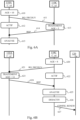
- Fig. 6A schematically illustrates an exchange of messages between the investigator equipment 110A and the responding equipment 110C of the routing network 100. Said exchange of messages results from the implementation of the management method by the investigator equipment 110A during the transient regime between the first configuration and the second configuration of the routing network 100.
- the investigating equipment 110A and the responding equipment 110C are both provided with the dynamic control service cd, and each ensures, at the start of the transient regime, the role of controller C.
- the investigator equipment 110A records its age at the present time.
- the age of the investigator equipment is 10 seconds, in other words, the investigator equipment has been acting as controller C for 10 seconds.
- the investigating equipment 110A broadcasts an initial discovery request RQ_DECOUV which is received by the responding equipment 110C and intended to search for any equipment ensuring the role of controller C and any equipment provided with the dynamic control service cd.
- the responding equipment 110C In a step 613, the responding equipment 110C, ensuring the role of controller C and provided with the dynamic control service cd, processes the initial discovery request RQ_DECOUV.
- the responding equipment 110C being provided with the dynamic control service cd further determines its age at the time of receipt of the initial discovery request RQ_DECOUV, which is 5 seconds according to an exemplary embodiment.
- the responding equipment 110C sends a REP response to the investigating equipment 110A.
- the REP response includes information representative of the controller role C such as the TLV format field including the value 0x00, information representative of the dynamic control service cd such as the TLV format field including the value 0x02 and information representative of the age of the responding equipment 110C being equal to 5 seconds.
- the investigating equipment 110A analyzes the REP response received from the responding equipment 110C.
- the investigating equipment 110A thus determines that the responding equipment 110C performs the role of controller C and is provided with the dynamic control service cd.
- the investigating equipment 110A then obtains the age of the responding equipment 110C in the REP response and compares its own age with the age of the responding equipment 110C in accordance with step 207 of the management method.
- Fig. 6B schematically illustrates an exchange of messages between the investigator equipment 110C, the responding equipment 110A and an equipment 120 of the routing network 100. Said exchange of messages results from an example of implementation of the management method by the investigator equipment 110C during the transient regime between the first configuration and the second configuration of the routing network 100.
- the investigating equipment 110C and the responding equipment 110A are both provided with the dynamic control service cd, and each assumes, at the start of the transient regime, the role of controller C.
- a first step 620 the investigator equipment 110C records its age at the present moment, said age being 8 seconds according to an exemplary embodiment.
- the investigating equipment 110C broadcasts an initial discovery request RQ_DECOUV which is received by the responding equipment 110A.
- the investigator equipment 110C determines that its controller function is active.
- the responding equipment 110A processes the initial discovery request RQ_DECOUV.
- the responding equipment 110A being provided with the dynamic control service cd determines its age at the time of receipt of the initial discovery request RQ_DECOUV, said age being 14 seconds according to an exemplary embodiment.
- the responding equipment 110A sends a REP response to the investigating equipment 110C.
- the REP response includes information representative of the controller role C such as the TLV format field including the value 0x00, information representative of the dynamic control service cd such as the TLV format field including the value 0x02 and information representative of the age of the responding equipment 110C equal to 14 seconds.
- the investigating equipment 110C analyzes the REP response received from the responding equipment 110A.
- the investigating equipment 110C determines that the responding equipment 110A performs the role of controller C and is provided with the dynamic control service cd.
- the investigating equipment 110C then obtains the age of the responding equipment 110A in the REP response and compares its own age, equal to 8 seconds, with the age of the responding equipment 110A, equal to 14 seconds, in accordance with step 207 of the management method.
- the investigating equipment 110C determines that the age of the investigating equipment 110C is less than the age of the responding equipment 110A.
- the investigator equipment 110C deactivates the controller function in accordance with step 208 of the management method.
- the investigating equipment 110C broadcasts in the routing network 100 a configuration change message CONFIG_RENEW comprising an identifier of the responding equipment 110A.
- the configuration change message CONFIG_RENEW is for example received by an equipment 120 of the routing network 100.
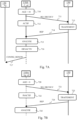
- Fig. 7A schematically illustrates an exchange of messages between the investigator equipment 110A, the responding equipment 130 and an equipment 120 of the routing network 100. Said exchange of messages results from an example of implementation of the management method by the investigator equipment 110A during the transient regime between the first configuration and the third configuration of the routing network 100.
- the investigating equipment 110A and the responding equipment 130 each perform, at the start of the transient regime, the role of controller C.
- the investigating equipment 110A is provided with the dynamic control service while the responding equipment 130 is devoid of the dynamic control service.
- the investigator equipment 110A records its age at the present moment.
- the investigating equipment 110A broadcasts an initial discovery request RQ_DECOUV which is received by the responding equipment 130 and which indicates a search for any equipment executing the controller function and any equipment provided with the dynamic control service cd.
- the investigator equipment 110A determines that its controller function is active at the time of broadcasting the initial discovery request RQ_DECOUV.
- the responding equipment 130 processes the initial discovery request RQ_DECOUV.
- the responding equipment 130 sends a REP response to the investigating equipment 110A.
- the REP response includes information representative of the controller role C such as the TLV format field including the value 0x00.
- the REP response does not include information representative of the dynamic control service cd.
- the investigating equipment 110A analyzes the REP response received from the responding equipment 130.
- the investigating equipment 110A thus determines that the responding equipment 130 performs the role of controller C and is devoid of the dynamic control service cd.
- the investigating equipment 110A then decides to deactivate its controller function in accordance with step 207 of the management method.
- step 716 similar to step 208 of the management method, the investigator equipment 110A deactivates its controller function.
- step 717 similar to step 209 of the management method, the investigating equipment broadcasts in the routing network 100 a configuration change message CONFIG_RENEW, which is received for example by the equipment 120.
- Fig. 7B schematically illustrates an exchange of messages between the investigator equipment 110A and the responder equipment 130 of the routing network 100.
- Said exchange of messages results from an example of implementation of the management method, according to a first embodiment, by the investigator equipment 110A during the steady state associated with the third configuration of the routing network 100.
- the responder equipment 130 ensures the role of controller C.
- the investigator equipment 110A is provided with the dynamic control service while the responder equipment 130 is devoid of the dynamic control service.
- the investigator equipment 110A records its age at the present time.
- the age of the investigator equipment 110A is zero since the investigator equipment does not perform the role of controller C.
- the investigating equipment 110A broadcasts an initial discovery request RQ_DECOUV which is received by the responding equipment 130.
- the investigator equipment 110A determines that its controller function is inactive at the time of broadcasting the initial discovery request. RQ_DECOUV.
- the investigator equipment 110A then initializes a counter c in accordance with step 301 of the management method.
- the responding equipment 130 processes the initial discovery request RQ_DECOUV.
- the responding equipment 130 sends a REP response to the investigating equipment 110A.
- the REP response includes information representative of the controller role C such as the TLV format field including the value 0x00.
- the REP response does not include information representative of the dynamic control service cd.
- the investigator equipment 110A analyzes the REP response received from the responder equipment 130.
- the investigator equipment 110A thus determines that the responder equipment 130 is performing the role of controller C.
- the investigator equipment 110A then decides to keep its controller function inactive and waits for the first predefined time period to elapse in accordance with step 310 of the management method before implementing the steps of the management method again.
- Fig. 8 schematically illustrates an example of implementation of the management method according to a first embodiment by the investigator equipment 110B during the transient regime between the first configuration and the fourth configuration of the routing network 100.
- the investigator equipment 110B is provided with the dynamic control service and does not, at the start of the transient regime, ensure the role of controller C (in other words, the investigator equipment 110B only executes the agent function Ag).
- a first step 801 the equipment 110A, which ensures the role of controller C in the first configuration of the routing network 100, is deleted from the routing network 100, for example due to a shutdown or a disconnection of said equipment 110A.
- the investigator equipment 110B records its age at the present time.
- the investigator equipment 110B broadcasts an initial discovery request RQ_DECOUV in the routing network 100.
- the initial discovery request RQ_DECOUV can be received by an equipment 120 but cannot be received by the equipment 110A which is switched off or disconnected from the routing network 100.
- the investigator equipment 110B determines that its controller function is inactive at the time of broadcasting the initial discovery request RQ_DECOUV.
- a responding device 120 processes the initial discovery request RQ_DECOUV.
- the responding equipment 120 transmits a REP response to the investigating equipment 110B.
- the REP response does not include information representative of the role of controller C nor information representative of the dynamic control service.
- the investigating equipment 110B determines that the responding equipment 120 is not performing the role of controller C and further considers that the second predefined time has elapsed since the broadcast of the initial discovery request RQ_DECOUV.
- the investigator equipment 110B broadcasts an additional discovery request RQ_DECOUV_B in the routing network 100, in accordance with step 306 of the management method.
- the additional discovery request RQ_DECOUV_B cannot be received by the equipment 110A.
- the additional discovery request RQ_DECOUV_B is also not received by another equipment of the routing network 100.
- the discovery request RQ_DECOUV_B could be received by an equipment 120 of the routing network in a similar manner to the initial discovery request RQ_DECOUV in step 811a.
- the investigator equipment 110B having not received a response after the second predefined delay following the broadcast of the previous additional discovery request RQ_DECOUV _B compares the counter c to the threshold n , in accordance with step 305 of the management method.
- the investigator equipment 110B then activates the controller function, in accordance with step 308 of the management method.
Landscapes
- Engineering & Computer Science (AREA)
- Computer Networks & Wireless Communication (AREA)
- Signal Processing (AREA)
- Computer Security & Cryptography (AREA)
- Computer Hardware Design (AREA)
- Computing Systems (AREA)
- General Engineering & Computer Science (AREA)
- Mobile Radio Communication Systems (AREA)
- Data Exchanges In Wide-Area Networks (AREA)
- Small-Scale Networks (AREA)
Claims (11)
- Verfahren zur Verwaltung einer Controller-Funktion einer Investigator-Einrichtung, wobei die Investigator-Einrichtung zu einem Routing-Netzwerk (100) gehört, wobei das Routing-Netzwerk (100) eine Mehrzahl von Einrichtungen (110A, 110B, 110C, 120, 130) umfasst, wobei jede Einrichtung des Routing-Netzwerks in der Lage ist, ein drahtloses Netzwerk so zu verwalten, dass das Routing-Netzwerk (100) ein vereinheitlichtes drahtloses Netzwerk bereitstellt, wobei mindestens eine Einrichtung des Routing-Netzwerks (100) die Controller-Funktion umfasst, wobei jede die Controller-Funktion umfassende Einrichtung eine Controller-Rolle (C) wahrnimmt, die impliziert, das Routing-Netzwerk (100) zu verwalten, wenn die Controller-Funktion der Einrichtung aktiv ist,wobei das Verfahren dadurch gekennzeichnet ist, dass die Investigator-Einrichtung mit einem dynamischen Steuerungsdienst (cd) versehen ist, wobei jede mit dem dynamischen Steuerungsdienst (cd) versehene Einrichtung die Controller-Funktion umfasst und die Fähigkeit umfasst, die Controller-Funktion zu aktivieren und zu deaktivieren, ohne einen Neustart zu erfordern, und dadurch, dass das Verfahren von der Investigator-Einrichtung implementiert wird und die folgenden Schritte umfasst:- Registrieren (201) eines Alters der Investigator-Einrichtung, wobei das Alter einer Einrichtung eine zu einem gegebenen Zeitpunkt bestimmte Dauer ist, seit der die Einrichtung die Controller-Rolle (C) wahrnimmt,- Ausgeben (201), sobald ein Alter der Investigator-Einrichtung registriert wurde, einer anfänglichen Discovery-Anforderung, die dazu bestimmt ist, jede Einrichtung des Routing-Netzwerks (100) zu identifizieren, die die Controller-Rolle (C) wahrnimmt,- Bestimmen (205), für jede Antwort auf die anfängliche Discovery-Anforderung, die von einer Einrichtung, antwortende Einrichtung genannt, empfangen wird, dass die antwortende Einrichtung die Controller-Rolle (C) wahrnimmt, gemäß einer in der empfangenen Antwort vorhandenen Information, die für die Controller-Rolle (C) repräsentativ ist,und das Verfahren ferner, wenn die Controller-Funktion der Investigator-Einrichtung zum Zeitpunkt des Ausgebens der anfänglichen Discovery-Anforderung aktiv ist, die folgenden Schritte:- Erhalten (207), in der empfangenen Antwort, des Alters der antwortenden Einrichtung, und- Deaktivieren (208) der Controller-Funktion der Investigator-Einrichtung, falls das Alter der Investigator-Einrichtung geringer als das Alter der antwortenden Einrichtung ist.
- Verfahren nach Anspruch 1, dadurch gekennzeichnet, dass die anfängliche Discovery-Anforderung ferner dazu bestimmt ist, jede Einrichtung des Routing-Netzwerks (100) zu identifizieren, die mit dem dynamischen Steuerungsdienst (cd) versehen ist, dadurch, dass das Verfahren ferner Folgendes umfasst:- Bestimmen (206), für jede Antwort auf die anfängliche Discovery-Anforderung, die von einer antwortenden Einrichtung empfangen wird, dass die antwortende Einrichtung mit dem dynamischen Steuerungsdienst (cd) versehen ist, gemäß einer in der empfangenen Antwort vorhandenen Information, die für den dynamischen Steuerungsdienst (cd) repräsentativ ist,- Deaktivieren (208) der Controller-Funktion der Investigator-Einrichtung, falls die antwortende Einrichtung die Controller-Rolle (C) wahrnimmt und nicht mit dem dynamischen Steuerungsdienst (cd) versehen ist, wenn die Controller-Funktion der Investigator-Einrichtung zum Zeitpunkt des Ausgebens der anfänglichen Discovery-Anforderung aktiv ist (203),
und dadurch, dass der Schritt des Erhaltens (207), in der empfangenen Antwort, des Alters der antwortenden Einrichtung durchgeführt wird, falls die antwortende Einrichtung, die die Controller-Rolle (C) wahrnimmt, ferner mit dem dynamischen Steuerungsdienst (cd) versehen ist. - Verfahren nach einem der Ansprüche 1 und 2, dadurch gekennzeichnet, dass es ferner Folgendes umfasst:- Senden (209), in dem Routing-Netzwerk (100), einer Konfigurationsänderungsnachricht, wenn die Investigator-Einrichtung die Controller-Funktion deaktiviert, wobei die Konfigurationsänderungsnachricht eine Kennung der die Controller-Rolle (C) wahrnehmenden antwortenden Einrichtung umfasst, so dass jede andere Einrichtung an die antwortende Einrichtung eine Konfigurationserneuerungsanfrage senden kann.
- Verfahren nach einem der Ansprüche 1 bis 3, dadurch gekennzeichnet, dass das Verfahren ferner, wenn die Controller-Funktion der Investigator-Einrichtung zum Zeitpunkt des Ausgebens der anfänglichen Discovery-Anforderung inaktiv ist (203), Folgendes umfasst:- Ausgeben (306) einer zusätzlichen Discovery-Anforderung, die identisch mit der anfänglichen Discovery-Anforderung ist, wenn keine während einer vorgegebenen ersten Frist nach dem Ausgeben der vorhergehenden Discovery-Anforderung empfangene Antwort es ermöglicht, eine andere Einrichtung des Routing-Netzwerks (100) zu identifizieren, die die Controller-Rolle (C) wahrnimmt,- Aktivieren (308) der Controller-Funktion der Einrichtung, wenn die Anzahl der gesendeten zusätzlichen Discovery-Anforderungen einen vorbestimmten Schwellenwert erreicht (305) und falls keine während der vorgegebenen ersten Frist nach dem Ausgeben der vorhergehenden Discovery-Anforderung empfangene Antwort es ermöglicht, eine andere Einrichtung des Routing-Netzwerks (100) zu identifizieren, die die Controller-Rolle (C) wahrnimmt.
- Verfahren nach einem der Ansprüche 1 bis 3, dadurch gekennzeichnet, dass das Verfahren ferner, wenn die Controller-Funktion der Investigator-Einrichtung zum Zeitpunkt des Ausgebens der anfänglichen Discovery-Anforderung inaktiv ist (203), Folgendes umfasst:- Ausgeben (306) einer zusätzlichen Discovery-Anforderung, die identisch mit der anfänglichen Discovery-Anforderung ist, wenn keine während einer vorgegebenen ersten Frist nach dem Ausgeben der vorhergehenden Discovery-Anforderung empfangene Antwort es ermöglicht, eine andere Einrichtung des Routing-Netzwerks (100) zu identifizieren, die die Controller-Rolle (C) wahrnimmt,- Aktivieren (308) der Controller-Funktion der Einrichtung, wenn keine empfangene Antwort es ermöglicht, eine andere Einrichtung des Routing-Netzwerks (100) zu identifizieren, die die Controller-Rolle (C) wahrnimmt, und falls eine vorgegebene zweite Frist, die ab dem Ausgeben der anfänglichen Discovery-Anforderung gezählt wird, verstrichen ist (314), wobei die vorgegebene zweite Frist länger als die vorgegebene erste Frist ist.
- Verfahren nach einem der Ansprüche 1 bis 5, dadurch gekennzeichnet, dass das Verfahren ferner Folgendes umfasst:- Registrieren eines neuen Alters der Investigator-Einrichtung und Ausgeben einer neuen anfänglichen Discovery-Anforderung, wenn die vorgegebene erste Frist, die ab dem Ausgeben der vorhergehenden anfänglichen Discovery-Anforderung gezählt wird, verstrichen ist (210, 220, 310).
- Verfahren nach einem der Ansprüche 1 bis 6, dadurch gekennzeichnet, dass jeder Schritt des Aktivierens oder Deaktivierens der Controller-Funktion durchgeführt wird, falls keine Aktivierung oder Deaktivierung der Controller-Funktion der Investigator-Einrichtung seit dem Ausgeben der vorhergehenden anfänglichen Anforderung durchgeführt worden ist.
- Investigator-Einrichtung, die zu einem Routing-Netzwerk (100) gehört, wobei das Routing-Netzwerk (100) eine Mehrzahl von Einrichtungen umfasst, wobei jede Einrichtung des Routing-Netzwerks (100) in der Lage ist, ein drahtloses Netzwerk zu verwalten, so dass das Routing-Netzwerk ein vereinheitlichtes drahtloses Netzwerk bereitstellt,wobei mindestens eine Einrichtung des Routing-Netzwerks (100) die Controller-Funktion umfasst, wobei jede die Controller-Funktion umfassende Einrichtung eine Controller-Rolle (C) wahrnimmt, die impliziert, das Routing-Netzwerk (100) zu verwalten, wenn die Controller-Funktion der Einrichtung aktiv ist,wobei die Investigator-Einrichtung dadurch gekennzeichnet ist, dass sie mit einem dynamischen Steuerungsdienst (cd) versehen ist, wobei jede mit dem dynamischen Steuerungsdienst versehene Einrichtung die Controller-Funktion umfasst und die Fähigkeit umfasst, die Controller-Funktion zu aktivieren und zu deaktivieren, ohne einen Neustart zu erfordern, und dadurch, dass sie umfasst:- Mittel zum Registrieren (201) eines Alters der Investigator-Einrichtung, wobei das Alter einer Einrichtung eine zu einem gegebenen Zeitpunkt bestimmte Dauer ist, seit der die Einrichtung die Controller-Rolle (C) wahrnimmt,- Mittel zum Ausgeben (201), sobald ein Alter der Investigator-Einrichtung registriert wurde, einer anfänglichen Discovery-Anforderung, die dazu bestimmt ist, jede Einrichtung des Routing-Netzwerks (100) zu identifizieren, die die Controller-Rolle (C) wahrnimmt,- Mittel zum Bestimmen (205), für jede Antwort auf die anfängliche Discovery-Anforderung, die von einer Einrichtung, antwortende Einrichtung genannt, empfangen wird, dass die antwortende Einrichtung die Controller-Rolle (C) wahrnimmt, gemäß einer in der empfangenen Antwort vorhandenen Information, die für die Controller-Rolle (C) repräsentativ ist,und die Investigator-Einrichtung ferner umfasst:- Mittel zum Erhalten (207), in der empfangenen Antwort, des Alters der antwortenden Einrichtung, wenn die Controller-Funktion der Investigator-Einrichtung zum Zeitpunkt des Ausgebens der anfänglichen Discovery-Anforderung aktiv ist, und- Mittel zum Deaktivieren (208) der Controller-Funktion der Investigator-Einrichtung, falls das Alter der Investigator-Einrichtung geringer als das Alter der antwortenden Einrichtung ist.
- Routing-Netzwerk (100), dadurch gekennzeichnet, dass das Verfahren nach einem der Ansprüche 1 bis 7 von jeder mit dem dynamischen Steuerungsdienst versehenen Einrichtung des Routing-Netzwerks (100) implementiert wird.
- Computerprogramm, das auf einem Medium gespeichert und/oder von einem Kommunikationsnetzwerk heruntergeladen werden kann, um von einem Prozessor gelesen zu werden, und dadurch gekennzeichnet ist, dass es Anweisungen umfasst, um das Verfahren nach einem der Ansprüche 1 bis 7 implementieren, wenn das Programm von dem Prozessor ausgeführt wird.
- Medium zum Speichern von Informationen, das ein Computerprogramm nach dem vorhergehenden Anspruch speichert.
Applications Claiming Priority (1)
| Application Number | Priority Date | Filing Date | Title |
|---|---|---|---|
| FR2108832A FR3126275B1 (fr) | 2021-08-23 | 2021-08-23 | Procede de gestion d’une fonction controleur par un equipement d’un reseau d’acheminement |
Publications (2)
| Publication Number | Publication Date |
|---|---|
| EP4142240A1 EP4142240A1 (de) | 2023-03-01 |
| EP4142240B1 true EP4142240B1 (de) | 2025-04-16 |
Family
ID=79170736
Family Applications (1)
| Application Number | Title | Priority Date | Filing Date |
|---|---|---|---|
| EP22191142.3A Active EP4142240B1 (de) | 2021-08-23 | 2022-08-19 | Verfahren zur verwaltung einer controller-funktion durch ein gerät eines router-netzwerks |
Country Status (5)
| Country | Link |
|---|---|
| US (1) | US12402207B2 (de) |
| EP (1) | EP4142240B1 (de) |
| CA (1) | CA3169425A1 (de) |
| ES (1) | ES3033710T3 (de) |
| FR (1) | FR3126275B1 (de) |
Family Cites Families (8)
| Publication number | Priority date | Publication date | Assignee | Title |
|---|---|---|---|---|
| US10248996B2 (en) * | 2009-01-28 | 2019-04-02 | Headwater Research Llc | Method for operating a wireless end-user device mobile payment agent |
| US20110202194A1 (en) * | 2010-02-15 | 2011-08-18 | General Electric Company | Sub-metering hardware for measuring energy data of an energy consuming device |
| TWI606737B (zh) * | 2016-06-17 | 2017-11-21 | 智易科技股份有限公司 | 區域網路拓撲管理系統和方法 |
| JP7102311B2 (ja) * | 2018-09-27 | 2022-07-19 | キヤノン株式会社 | 通信装置、通信装置の制御方法、およびプログラム |
| US11388136B2 (en) * | 2019-06-18 | 2022-07-12 | Nutanix, Inc. | Dynamic distributed service location discovery |
| JP2021043689A (ja) * | 2019-09-11 | 2021-03-18 | キオクシア株式会社 | ストレージシステム、ストレージデバイスおよびストレージシステムの制御方法 |
| DE102021132102A1 (de) * | 2021-12-07 | 2023-06-07 | Bayerische Motoren Werke Aktiengesellschaft | Verfahren, Computerprogramm, Vorrichtung und Fahrzeug zur Verbesserung einer Performance eines Bilderkennungssystems |
| US20250007783A1 (en) * | 2023-06-30 | 2025-01-02 | Veea Inc. | Methods and Systems for Micro Edge Self Provisioning |
-
2021
- 2021-08-23 FR FR2108832A patent/FR3126275B1/fr not_active Expired - Fee Related
-
2022
- 2022-08-03 CA CA3169425A patent/CA3169425A1/fr active Pending
- 2022-08-09 US US17/884,140 patent/US12402207B2/en active Active
- 2022-08-19 ES ES22191142T patent/ES3033710T3/es active Active
- 2022-08-19 EP EP22191142.3A patent/EP4142240B1/de active Active
Also Published As
| Publication number | Publication date |
|---|---|
| ES3033710T3 (en) | 2025-08-07 |
| US12402207B2 (en) | 2025-08-26 |
| CA3169425A1 (fr) | 2023-02-23 |
| FR3126275B1 (fr) | 2023-11-03 |
| EP4142240A1 (de) | 2023-03-01 |
| FR3126275A1 (fr) | 2023-02-24 |
| US20230058260A1 (en) | 2023-02-23 |
Similar Documents
| Publication | Publication Date | Title |
|---|---|---|
| EP3787344A1 (de) | Verfahren zur konfiguration eines systems zur erweiterung der drahtlosen kommunikationsabdeckung, und system zur erweiterung der drahtlosen kommunikationsabdeckung, das dieses verfahren umsetzt | |
| EP2901771B1 (de) | Versetzung eines mit einem multilink-netzwerk verbundenen anlagenteils in einen standby-modus | |
| EP3714642B1 (de) | Verfahren zur verwaltung einer optimalen sendeleistung eines wi-fi-zugangspunktes und entsprechender wi-fi-zugangspunkt | |
| EP4142240A1 (de) | Verfahren zur verwaltung einer controller-funktion durch ein gerät eines router-netzwerks | |
| EP3053309A1 (de) | Verbesserte verwaltung von netzwerkverbindungen | |
| FR2995482A1 (fr) | Gestion de l'utilisation d'une passerelle par une pluralite de terminaux | |
| EP3087785B1 (de) | Übertragungssystem mit erster und zweiter brückenvorrichtung | |
| EP4013096B1 (de) | Mehrfach-pairing | |
| FR3091128A1 (fr) | Procédé et système de gestion de serveurs dhcp | |
| EP4292380B1 (de) | Übertragung von daten von einem kommunikationsnetz zu einem teilnehmergerät | |
| EP4482225B1 (de) | Verfahren zur verwaltung eines aktivierungszustands einer knotenvorrichtung eines kommunikationsnetzwerks, entsprechende vorrichtung, knotenvorrichtung, system und computerprogramm | |
| EP2583429B1 (de) | Verfahren und system zur kommunikation auf der basis von ws-discovery | |
| EP3545384B1 (de) | System zur verwaltung des stromverbrauchs in einer vorrichtung | |
| CA2892956A1 (fr) | Dispositif et procede de configuration d'un dispositif de communication | |
| EP2594038B1 (de) | Detektion eines upnp steuerungsmoduls | |
| EP3389232A1 (de) | Verfahren zur konfiguration von nachrichtenverbreitung | |
| EP2191628A2 (de) | Automatischer quellenkonzentrator für ein multimedia-system | |
| EP4668715A1 (de) | Verfahren zur konfiguration eines kommunikationsprotokolls einer knotenvorrichtung | |
| EP2517412B1 (de) | Sicherungsvorrichtung einer upnp-steuerung | |
| FR3031646A1 (fr) | Procede de gestion de la selection de dispositifs pour la realisation d'un service | |
| EP4639961A1 (de) | Verfahren, die von einer kommunikationsvorrichtung in einem drahtlosen netzwerk und einer client-vorrichtung ausgeführt werden, und zugehörige vorrichtungen | |
| EP4568212A1 (de) | Verfahren und vorrichtung zur verwaltung der aktualisierung eines endgerätes in einem telekommunikationsnetz. | |
| WO2025125478A1 (fr) | Procédés de supervision, de gestion d'un service, de gestion d'un accès à une tranche réseau et d'accès à un service, et dispositifs configurés pour mettre en oeuvre ces procédés | |
| FR3122055A1 (fr) | Procédé de traitement d’une demande d’activation d’au moins une interface d’un équipement hôte avec au moins un réseau de communication local géré par ledit équipement hôte, procédé de demande d’activation de ladite au moins une interface, dispositifs, équipement hôte, équipement terminal, système de gestion et programmes d’ordinateur correspondants. | |
| FR3089744A1 (fr) | Procede de configuration automatique par canal audio d’un dispositif sans fil |
Legal Events
| Date | Code | Title | Description |
|---|---|---|---|
| PUAI | Public reference made under article 153(3) epc to a published international application that has entered the european phase |
Free format text: ORIGINAL CODE: 0009012 |
|
| STAA | Information on the status of an ep patent application or granted ep patent |
Free format text: STATUS: EXAMINATION IS IN PROGRESS |
|
| 17P | Request for examination filed |
Effective date: 20220819 |
|
| AK | Designated contracting states |
Kind code of ref document: A1 Designated state(s): AL AT BE BG CH CY CZ DE DK EE ES FI FR GB GR HR HU IE IS IT LI LT LU LV MC MK MT NL NO PL PT RO RS SE SI SK SM TR |
|
| RBV | Designated contracting states (corrected) |
Designated state(s): AL AT BE BG CH CY CZ DE DK EE ES FI FR GB GR HR HU IE IS IT LI LT LU LV MC MK MT NL NO PL PT RO RS SE SI SK SM TR |
|
| RAP3 | Party data changed (applicant data changed or rights of an application transferred) |
Owner name: SAGEMCOM BROADBAND SAS |
|
| GRAP | Despatch of communication of intention to grant a patent |
Free format text: ORIGINAL CODE: EPIDOSNIGR1 |
|
| STAA | Information on the status of an ep patent application or granted ep patent |
Free format text: STATUS: GRANT OF PATENT IS INTENDED |
|
| RIC1 | Information provided on ipc code assigned before grant |
Ipc: H04W 84/20 20090101ALN20241011BHEP Ipc: H04W 84/12 20090101ALN20241011BHEP Ipc: H04L 41/00 20220101ALI20241011BHEP Ipc: H04L 41/12 20220101AFI20241011BHEP |
|
| INTG | Intention to grant announced |
Effective date: 20241119 |
|
| GRAS | Grant fee paid |
Free format text: ORIGINAL CODE: EPIDOSNIGR3 |
|
| GRAA | (expected) grant |
Free format text: ORIGINAL CODE: 0009210 |
|
| STAA | Information on the status of an ep patent application or granted ep patent |
Free format text: STATUS: THE PATENT HAS BEEN GRANTED |
|
| AK | Designated contracting states |
Kind code of ref document: B1 Designated state(s): AL AT BE BG CH CY CZ DE DK EE ES FI FR GB GR HR HU IE IS IT LI LT LU LV MC MK MT NL NO PL PT RO RS SE SI SK SM TR |
|
| REG | Reference to a national code |
Ref country code: GB Ref legal event code: FG4D Free format text: NOT ENGLISH |
|
| REG | Reference to a national code |
Ref country code: CH Ref legal event code: EP |
|
| REG | Reference to a national code |
Ref country code: IE Ref legal event code: FG4D Free format text: LANGUAGE OF EP DOCUMENT: FRENCH |
|
| REG | Reference to a national code |
Ref country code: DE Ref legal event code: R096 Ref document number: 602022013169 Country of ref document: DE |
|
| REG | Reference to a national code |
Ref country code: ES Ref legal event code: FG2A Ref document number: 3033710 Country of ref document: ES Kind code of ref document: T3 Effective date: 20250807 |
|
| REG | Reference to a national code |
Ref country code: NL Ref legal event code: MP Effective date: 20250416 |
|
| PG25 | Lapsed in a contracting state [announced via postgrant information from national office to epo] |
Ref country code: NL Free format text: LAPSE BECAUSE OF FAILURE TO SUBMIT A TRANSLATION OF THE DESCRIPTION OR TO PAY THE FEE WITHIN THE PRESCRIBED TIME-LIMIT Effective date: 20250416 |
|
| REG | Reference to a national code |
Ref country code: AT Ref legal event code: MK05 Ref document number: 1786607 Country of ref document: AT Kind code of ref document: T Effective date: 20250416 |
|
| PG25 | Lapsed in a contracting state [announced via postgrant information from national office to epo] |
Ref country code: FI Free format text: LAPSE BECAUSE OF FAILURE TO SUBMIT A TRANSLATION OF THE DESCRIPTION OR TO PAY THE FEE WITHIN THE PRESCRIBED TIME-LIMIT Effective date: 20250416 Ref country code: PT Free format text: LAPSE BECAUSE OF FAILURE TO SUBMIT A TRANSLATION OF THE DESCRIPTION OR TO PAY THE FEE WITHIN THE PRESCRIBED TIME-LIMIT Effective date: 20250818 |
|
| PGFP | Annual fee paid to national office [announced via postgrant information from national office to epo] |
Ref country code: ES Payment date: 20250901 Year of fee payment: 4 |
|
| PGFP | Annual fee paid to national office [announced via postgrant information from national office to epo] |
Ref country code: DE Payment date: 20250724 Year of fee payment: 4 |
|
| REG | Reference to a national code |
Ref country code: LT Ref legal event code: MG9D |
|
| PG25 | Lapsed in a contracting state [announced via postgrant information from national office to epo] |
Ref country code: NO Free format text: LAPSE BECAUSE OF FAILURE TO SUBMIT A TRANSLATION OF THE DESCRIPTION OR TO PAY THE FEE WITHIN THE PRESCRIBED TIME-LIMIT Effective date: 20250716 Ref country code: GR Free format text: LAPSE BECAUSE OF FAILURE TO SUBMIT A TRANSLATION OF THE DESCRIPTION OR TO PAY THE FEE WITHIN THE PRESCRIBED TIME-LIMIT Effective date: 20250717 |
|
| PG25 | Lapsed in a contracting state [announced via postgrant information from national office to epo] |
Ref country code: PL Free format text: LAPSE BECAUSE OF FAILURE TO SUBMIT A TRANSLATION OF THE DESCRIPTION OR TO PAY THE FEE WITHIN THE PRESCRIBED TIME-LIMIT Effective date: 20250416 |
|
| PG25 | Lapsed in a contracting state [announced via postgrant information from national office to epo] |
Ref country code: BG Free format text: LAPSE BECAUSE OF FAILURE TO SUBMIT A TRANSLATION OF THE DESCRIPTION OR TO PAY THE FEE WITHIN THE PRESCRIBED TIME-LIMIT Effective date: 20250416 |
|
| PG25 | Lapsed in a contracting state [announced via postgrant information from national office to epo] |
Ref country code: HR Free format text: LAPSE BECAUSE OF FAILURE TO SUBMIT A TRANSLATION OF THE DESCRIPTION OR TO PAY THE FEE WITHIN THE PRESCRIBED TIME-LIMIT Effective date: 20250416 |
|
| PG25 | Lapsed in a contracting state [announced via postgrant information from national office to epo] |
Ref country code: AT Free format text: LAPSE BECAUSE OF FAILURE TO SUBMIT A TRANSLATION OF THE DESCRIPTION OR TO PAY THE FEE WITHIN THE PRESCRIBED TIME-LIMIT Effective date: 20250416 |
|
| PGFP | Annual fee paid to national office [announced via postgrant information from national office to epo] |
Ref country code: FR Payment date: 20250725 Year of fee payment: 4 |
|
| PG25 | Lapsed in a contracting state [announced via postgrant information from national office to epo] |
Ref country code: RS Free format text: LAPSE BECAUSE OF FAILURE TO SUBMIT A TRANSLATION OF THE DESCRIPTION OR TO PAY THE FEE WITHIN THE PRESCRIBED TIME-LIMIT Effective date: 20250716 |
|
| PG25 | Lapsed in a contracting state [announced via postgrant information from national office to epo] |
Ref country code: IS Free format text: LAPSE BECAUSE OF FAILURE TO SUBMIT A TRANSLATION OF THE DESCRIPTION OR TO PAY THE FEE WITHIN THE PRESCRIBED TIME-LIMIT Effective date: 20250816 |
|
| PG25 | Lapsed in a contracting state [announced via postgrant information from national office to epo] |
Ref country code: LV Free format text: LAPSE BECAUSE OF FAILURE TO SUBMIT A TRANSLATION OF THE DESCRIPTION OR TO PAY THE FEE WITHIN THE PRESCRIBED TIME-LIMIT Effective date: 20250416 |
|
| PG25 | Lapsed in a contracting state [announced via postgrant information from national office to epo] |
Ref country code: SM Free format text: LAPSE BECAUSE OF FAILURE TO SUBMIT A TRANSLATION OF THE DESCRIPTION OR TO PAY THE FEE WITHIN THE PRESCRIBED TIME-LIMIT Effective date: 20250416 Ref country code: DK Free format text: LAPSE BECAUSE OF FAILURE TO SUBMIT A TRANSLATION OF THE DESCRIPTION OR TO PAY THE FEE WITHIN THE PRESCRIBED TIME-LIMIT Effective date: 20250416 |
|
| REG | Reference to a national code |
Ref country code: DE Ref legal event code: R097 Ref document number: 602022013169 Country of ref document: DE |
|
| PG25 | Lapsed in a contracting state [announced via postgrant information from national office to epo] |
Ref country code: CZ Free format text: LAPSE BECAUSE OF FAILURE TO SUBMIT A TRANSLATION OF THE DESCRIPTION OR TO PAY THE FEE WITHIN THE PRESCRIBED TIME-LIMIT Effective date: 20250416 |
|
| PG25 | Lapsed in a contracting state [announced via postgrant information from national office to epo] |
Ref country code: EE Free format text: LAPSE BECAUSE OF FAILURE TO SUBMIT A TRANSLATION OF THE DESCRIPTION OR TO PAY THE FEE WITHIN THE PRESCRIBED TIME-LIMIT Effective date: 20250416 |
|
| PG25 | Lapsed in a contracting state [announced via postgrant information from national office to epo] |
Ref country code: SK Free format text: LAPSE BECAUSE OF FAILURE TO SUBMIT A TRANSLATION OF THE DESCRIPTION OR TO PAY THE FEE WITHIN THE PRESCRIBED TIME-LIMIT Effective date: 20250416 |
|
| PG25 | Lapsed in a contracting state [announced via postgrant information from national office to epo] |
Ref country code: IT Free format text: LAPSE BECAUSE OF FAILURE TO SUBMIT A TRANSLATION OF THE DESCRIPTION OR TO PAY THE FEE WITHIN THE PRESCRIBED TIME-LIMIT Effective date: 20250416 |
|
| PG25 | Lapsed in a contracting state [announced via postgrant information from national office to epo] |
Ref country code: RO Free format text: LAPSE BECAUSE OF FAILURE TO SUBMIT A TRANSLATION OF THE DESCRIPTION OR TO PAY THE FEE WITHIN THE PRESCRIBED TIME-LIMIT Effective date: 20250416 |
|
| PLBE | No opposition filed within time limit |
Free format text: ORIGINAL CODE: 0009261 |
|
| STAA | Information on the status of an ep patent application or granted ep patent |
Free format text: STATUS: NO OPPOSITION FILED WITHIN TIME LIMIT |
|
| REG | Reference to a national code |
Ref country code: CH Ref legal event code: L10 Free format text: ST27 STATUS EVENT CODE: U-0-0-L10-L00 (AS PROVIDED BY THE NATIONAL OFFICE) Effective date: 20260225 |
|
| REG | Reference to a national code |
Ref country code: CH Ref legal event code: H13 Free format text: ST27 STATUS EVENT CODE: U-0-0-H10-H13 (AS PROVIDED BY THE NATIONAL OFFICE) Effective date: 20260324 |
|
| 26N | No opposition filed |
Effective date: 20260119 |
|
| PG25 | Lapsed in a contracting state [announced via postgrant information from national office to epo] |
Ref country code: MC Free format text: LAPSE BECAUSE OF FAILURE TO SUBMIT A TRANSLATION OF THE DESCRIPTION OR TO PAY THE FEE WITHIN THE PRESCRIBED TIME-LIMIT Effective date: 20250416 |
|
| PG25 | Lapsed in a contracting state [announced via postgrant information from national office to epo] |
Ref country code: LU Free format text: LAPSE BECAUSE OF NON-PAYMENT OF DUE FEES Effective date: 20250819 |
|
| PG25 | Lapsed in a contracting state [announced via postgrant information from national office to epo] |
Ref country code: CH Free format text: LAPSE BECAUSE OF NON-PAYMENT OF DUE FEES Effective date: 20250831 |
|
| REG | Reference to a national code |
Ref country code: BE Ref legal event code: MM Effective date: 20250831 |
|
| PG25 | Lapsed in a contracting state [announced via postgrant information from national office to epo] |
Ref country code: LT Free format text: LAPSE BECAUSE OF FAILURE TO SUBMIT A TRANSLATION OF THE DESCRIPTION OR TO PAY THE FEE WITHIN THE PRESCRIBED TIME-LIMIT Effective date: 20250416 |
|
| PG25 | Lapsed in a contracting state [announced via postgrant information from national office to epo] |
Ref country code: IE Free format text: LAPSE BECAUSE OF NON-PAYMENT OF DUE FEES Effective date: 20250819 Ref country code: BE Free format text: LAPSE BECAUSE OF NON-PAYMENT OF DUE FEES Effective date: 20250831 |
|
| PG25 | Lapsed in a contracting state [announced via postgrant information from national office to epo] |
Ref country code: SE Free format text: LAPSE BECAUSE OF FAILURE TO SUBMIT A TRANSLATION OF THE DESCRIPTION OR TO PAY THE FEE WITHIN THE PRESCRIBED TIME-LIMIT Effective date: 20250416 |