EP4292380B1 - Übertragung von daten von einem kommunikationsnetz zu einem teilnehmergerät - Google Patents
Übertragung von daten von einem kommunikationsnetz zu einem teilnehmergerät Download PDFInfo
- Publication number
- EP4292380B1 EP4292380B1 EP22708586.7A EP22708586A EP4292380B1 EP 4292380 B1 EP4292380 B1 EP 4292380B1 EP 22708586 A EP22708586 A EP 22708586A EP 4292380 B1 EP4292380 B1 EP 4292380B1
- Authority
- EP
- European Patent Office
- Prior art keywords
- network
- session
- user equipment
- data
- request
- Prior art date
- Legal status (The legal status is an assumption and is not a legal conclusion. Google has not performed a legal analysis and makes no representation as to the accuracy of the status listed.)
- Active
Links
Images


Classifications
-
- H—ELECTRICITY
- H04—ELECTRIC COMMUNICATION TECHNIQUE
- H04W—WIRELESS COMMUNICATION NETWORKS
- H04W24/00—Supervisory, monitoring or testing arrangements
- H04W24/08—Testing, supervising or monitoring using real traffic
-
- H—ELECTRICITY
- H04—ELECTRIC COMMUNICATION TECHNIQUE
- H04W—WIRELESS COMMUNICATION NETWORKS
- H04W60/00—Affiliation to network, e.g. registration; Terminating affiliation with the network, e.g. de-registration
- H04W60/04—Affiliation to network, e.g. registration; Terminating affiliation with the network, e.g. de-registration using triggered events
-
- H—ELECTRICITY
- H04—ELECTRIC COMMUNICATION TECHNIQUE
- H04W—WIRELESS COMMUNICATION NETWORKS
- H04W68/00—User notification, e.g. alerting and paging, for incoming communication, change of service or the like
- H04W68/02—Arrangements for increasing efficiency of notification or paging channel
-
- H—ELECTRICITY
- H04—ELECTRIC COMMUNICATION TECHNIQUE
- H04W—WIRELESS COMMUNICATION NETWORKS
- H04W76/00—Connection management
- H04W76/10—Connection setup
Definitions
- the present invention relates to the transmission of data from a communication network to user equipment, and more particularly to the transmission of authentication data to a mobile terminal.
- the network measures the volume of downstream data intended for a mobile terminal, the transmission mode in the control plane being favored by the network when these data have a low volume, and vice versa.
- This mechanism is based on discrimination based on the volume of data, and thus induces that the low-volume downstream data are systematically transmitted in the control plane, which is not always an optimal solution in terms of network resource management, in particular when the mobile terminal is already connected to the user plane of the mobile network.
- the mobile terminal indicates to the network its own preference between these two transmission modes, so that this is taken into account by the network when deciding on the transmission mode for downstream data. transmit to the mobile terminal.
- This other proposal then requires an adaptation at the level of mobile terminals, which can prove tricky to implement.
- NPNs Non-Public Networks
- 5G technology a company using an NPN wants to connect to its NPN a device that it purchased "off the shelf", i.e. this device was not pre-configured during its manufacture with the authentication information (known as "credentials") necessary for its registration on the NPN.
- the document TR 23.700-07 furthermore envisages two modes of receiving this authentication information, namely a first mode of transmission in the user plane, at the initiative of the user equipment, where the user equipment requests the establishment of a PDU session and then uses the IP connectivity offered by this PDU session to establish a connection to the PS and a second mode of transmission in the control plane, at the initiative of the network, which then requires the network to have knowledge of the mode to be used in order to trigger or not the transmission mode in the control plane, since some terminals may support only one of these two modes.
- the present invention aims to remedy the drawbacks of the implementations proposed above, by proposing a method for selecting a transmission mode which does not have the drawbacks of these implementations.
- This method may further comprise, when the establishment of a session with the user equipment is detected before the expiration of said delay, the transmission to the user equipment, by means of said session, of said data.
- the detection of the reception of said request further comprises the transmission, from the first network entity to the network equipment, of a notification message of the reception of said request by the first network entity, said monitoring being triggered by the reception of the notification message by the network equipment.
- this session is an application session established between the network equipment and the user equipment.
- this session is a data exchange session established by means of a session management entity
- said monitoring of the establishment of a session comprises the monitoring, by the network equipment, of the reception of a notification message of the establishment of a data exchange session, the transmission of which is triggered by said session management entity following the establishment of a data exchange session by means of the session management entity.
- said transmission to the user equipment of the signaling messages containing said data comprises the transmission, from the second network entity to the network equipment, of a request instructing the network equipment to transmit said data to a third network entity and the transmission, from said third network entity to the user equipment, of at least one signaling message containing said data.
- the reception of said request triggers the monitoring of the establishment of a session with the user equipment.
- said monitoring of the establishment of a session comprises the monitoring, by the second network entity, of the reception of a notification message whose transmission is triggered by said session management entity following the establishment of a session established by means of the session management entity.
- said monitoring of the establishment of a session comprises the monitoring, by the second network entity, of the transmission between the session management entity and the user equipment of a confirmation message of the establishment of a data exchange session with the user equipment.
- the network equipment transmits to the second network entity a notification message for the establishment of a data exchange session following the establishment of said application session.
- said network equipment above is an authentication data provisioning server and said data is authentication data.
- a network entity suitable for use in a communication network, said network entity being configured to monitor whether a session with a user equipment through the communication network is established following the detection of the reception of a request to obtain data, sent by said user equipment, and if no establishment of a session with said user equipment is detected before the expiration of a time period after said detection of the reception of said request, trigger the transmission to the user equipment of at least one signaling message containing said data.
- a system comprising the above network entity as well as another network entity capable of being used in a communication network, this other network entity being configured to detect the reception of a request to obtain data, sent by said user equipment, and, following the detection of the reception of said request, trigger the monitoring for a determined duration of the establishment of a session with said user equipment through the communication network.
- a user equipment suitable for use with a communication network, said user equipment being configured to transmit, to a network entity of the communication network, a request to obtain data and to receive in return, from a network entity of the communication network, at least one signaling message containing said data, transmitted following the expiration of a time period after the reception of said request without a session through the network being established with said user equipment.
- This user equipment may advantageously further comprise a timer module, configured to be triggered by the transmission of the request to obtain data and blocking the transmission of a session establishment request to the network until the expiration of a determined duration after the triggering of the timer module.
- a timer module configured to be triggered by the transmission of the request to obtain data and blocking the transmission of a session establishment request to the network until the expiration of a determined duration after the triggering of the timer module.
- This user equipment may advantageously be further configured to insert an identifier of said user equipment into a connection request intended for a network equipment from which said data is available and transmit said connection request to said network equipment, in order to trigger the retrieval of said data by the network equipment by means of said identifier and the reception of said data via a connection with the network equipment.
- This method is used in the context of data transmission, through a communication network 100, from network equipment 60 to user equipment 1 (for example a smartphone, a tablet, a mobile phone, a portable PC, communicating object, etc.).
- network equipment 60 for example a smartphone, a tablet, a mobile phone, a portable PC, communicating object, etc.
- This network equipment 60 is typically a third-party network equipment, located in a network external to the communication network 100 and connected to the latter via a network router 40 acting as an access gateway to the external networks, but may also be a network equipment belonging to the core part of this network, when it is a mobile communication network. It may in particular be a server, which can be designated as a provisioning server, storing certain data to be provided to the user equipment, and more particularly an authentication data provisioning server.
- the data considered here may be more particularly data usable by the user equipment UE (in the sense that once received by this user equipment, they can be stored there for later use by this user equipment) and available in this network equipment 60, either because they are stored there, or because this network equipment 60 generates them in advance or on the fly, or because this network equipment 60 can receive them from another network equipment.
- they may be authentication data, allowing the user equipment to authenticate itself in order to be able to access a network, which are called "credentials" in English, which may be generated and/or stored by an authentication data provisioning server.
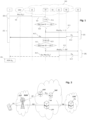
- This process firstly includes detection (phase D on the figure 1 ) of the reception (step D1) of a request (Req (d UE ) on the figure 1 ), transmitted by user equipment 1, to obtain data (from UE on the figure 1 ).
- This detection can be implemented by a network entity 10 (which can also be called a network node) of the communication network 100.
- This network entity 10 responsible here for detecting the reception of the request to obtain UE data transmitted by the equipment 1, can be an entity of the network 100 distinct from the aforementioned network equipment 60 or merged with it, depending on the embodiments.
- This detection D can be direct, when this network entity 10 itself receives this request, or indirect, when another network entity receives this request and notifies the network entity 10 thereof.
- this request may in particular be a network registration request (“REGISTER REQUEST”) as defined in the 3GPP TS 23.502 (v16.7.1) specification relating to the 5G standard, in which an indication is inserted that the UE equipment wishes to obtain this data.
- REGISTER REQUEST a network registration request
- 3GPP TS 23.502 (v16.7.1) specification relating to the 5G standard, in which an indication is inserted that the UE equipment wishes to obtain this data.
- This monitoring step can be implemented by a network entity 20 which can be distinct from the network entity 10 and the network equipment 60 mentioned above, or merged with one of them, according to the embodiments.
- this monitoring can be triggered in particular by the reception of a notification message sent (step D2) by the network entity 10 after it has received the request from the equipment 1 to obtain data.
- the establishment of a session with the equipment 1 can be directly detected by the network entity 20, as illustrated in the figure 1 . This is particularly the case when this network entity 20 is merged with the network equipment 60 and a session is established between the equipment 1 and the network equipment 60, for example an application session. This is also the case when the session is a data exchange session established by means of a session management entity 50, as may be the case for a PDU session, and the network entity 20 intercepts a message from the session management entity confirming the establishment of such a session with equipment 1.
- the establishment of a session with the UE equipment may also be indirectly detected by the network entity 20, by means of a notification received from a network entity involved in the establishment of this session.
- This is in particular the case when this network entity 20 is distinct from the network equipment 60, that a session (for example an application session) is established between the UE equipment and the network equipment 60 and that the network equipment 60 notifies the network entity of the establishment of this session.
- This is also the case when the session is a data exchange session established by means of a session management entity distinct from the network entity 20, as may be the case for a PDU session ("PDU Session" in English), this session management entity then notifying the network entity 20 when such a session is established.
- PDU Session PDU Session
- This monitoring phase S is a temporary monitoring phase, at the end of which a decision to transmit the UE data in the control plane is taken if no decision to transmit this same data in the user plane has been taken previously during this monitoring phase.
- this monitoring phase can be initiated by the triggering (step S11) of a timer upon detection of the reception of the request sent by the user equipment (i.e. at time t 0 on the figure 1 ), this timer expiring after the elapse of a certain time period d (step S15), which may be predetermined or (re)configurable by the operator of the communication network.
- This time period d may be of the order of a few seconds, for example 5 or 10 seconds.
- this timeout may be associated with an identifier of the user equipment (e.g. its SUPI identifier or its PEI hardware identifier) having issued the request, typically by extracting this identifier from the request itself, which makes it possible to maintain a list of different timeouts (potentially triggered at different times) associated with different user equipment identifiers, and thus distinguish and independently manage different user equipments which would request data at the same time.
- an identifier of the user equipment e.g. its SUPI identifier or its PEI hardware identifier
- a first transmission mode (A in the figure 1 ), in the user plane, is to be used to provide the UE data to the UE equipment, by means of the session established with this equipment 1 (step S13).
- the UE data are then transmitted to this user equipment 1 by means of the session whose establishment has been detected.
- the network entity 20 sends an instruction to the network equipment 60 (step A11) to trigger this transmission (steps A12, A13).
- this transmission is done through the network entity 40 of the network 1 (which can also be designated by the term “gateway”) allowing the interconnection of the network 1 with other third-party networks with regard to the user plane.
- these UE data are inserted into signaling messages transmitted to the equipment 1 by a network entity 30, these UE data thus being transmitted in the control plane rather than in the user plane of the network.
- This network entity 30, responsible here for transmitting to the equipment 1 the signaling messages in which the data usable by the equipment 1 have been inserted, may be distinct from the network entities 10, 20, 40 and the network equipment 60 mentioned above, or merged with one of these (in particular with the network entity 10), depending on the embodiments.
- the network entity 20 When the network entity 30 is not confused with the network equipment 60, the network entity 20 (responsible for monitoring the establishment of a session) sends a request message to the network equipment 60 (step B11) instructing it to provide the network entity 30 with this data (step B12), the network entity 30 then being able to insert this data into signaling messages (Msg (d UE )) that it transmits to the UE equipment (step B13), which can store it after reception (step M1) for later use.
- Msg signaling messages
- the selection of the transmission mode is thus carried out by the network on the basis of the speed with which a session is established with the user equipment UE after the latter has sent a request to the network to obtain data, and this in a manner controlled by the network (therefore by its operator) through the delay d.
- FIG. 2 illustrates the architecture of a network as defined in the 3GPP specifications for the 5G standard, in which the steps of this method can be implemented according to different embodiments of the present invention.
- the 5GC core of this network comprises the following entities: One (or more) “AMF” (for “Access and Mobility Management Function” in English) entity, belonging to the control plane of this network, able to receive requests from the UE equipment and able to transmit signaling messages to this UE equipment.
- AMF Access and Mobility Management Function
- SMS Session Management Function
- UPF User Plane Function
- NEF Network Exposure Function
- UDM Unified Data Management
- the user plane is defined by the N3 and N6 interfaces, while the control plane is defined by the N1, N4 and N11 interfaces, among others.
- the network entities 10 and 30 are implemented by the same AMF entity of a 5G core network
- the network entity 40 is implemented by a UPF entity of this same 5G core network
- the network entity 20 and the network equipment 60 are implemented by a PS provisioning server, external to this network but accessible via the UPF entity by means of the IP protocol, in which cred UE authentication data are generated and/or stored that can be used by the user equipment UE to be able to authenticate itself with certain networks in order to access them.
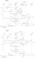
- the user equipment UE transmits (step D102) to the AMF node, which receives it, a request aimed at obtaining the cred UE authentication data, here in the form of a network registration request, “REGISTER REQUEST” as defined in the TS 23.501 specification, containing an indication of the UE equipment's desire to obtain this data (step S101).
- a request aimed at obtaining the cred UE authentication data here in the form of a network registration request, “REGISTER REQUEST” as defined in the TS 23.501 specification, containing an indication of the UE equipment's desire to obtain this data (step S101).
- Such a request may in particular be a specific registration request, such as a REGISTER request containing an indication that this registration is a registration for provisioning ("Register request for Onboarding" in English).
- a request may also comprise an identifier of the UE equipment, for example its SUPI identifier or its PEI hardware identifier.
- the AMF entity When it receives this request and notes that the UE equipment is requesting the provisioning of authentication data, the AMF entity transmits to the provisioning server PS, possibly via an NEF entity, a notification message of the receipt of such a request (step D103), this notification message advantageously containing the SUPI UE identifier of the UE equipment in order to allow the PS server to identify the UE equipment requesting authentication data.
- the AMF node can be configured to spontaneously send this notification message to the PS server, after receiving the request and detecting in it the desire to obtain the authentication data.
- the PS server may transmit (step D101) beforehand to the AMF node, possibly via a NEF entity, a request for subscription to notification of an event corresponding to the reception of such a request, in order to trigger the sending of such a notification message when this event actually takes place.
- a subscription request may be implemented similarly to the subscription request illustrated in the 3GPP TS TR 23.700-07 (v.1.2.0), clause 6.30.3.2, step 0b, by subscribing to the AMF for notification of an event of the "register for onboarding" type, which then allows the AMF entity to notify the PS server as soon as it receives a registration request containing an indication that this registration is for provisioning.
- the PS server Upon receipt of this notification sent by the AMF, the PS server triggers a phase S of monitoring the establishment of a session with this UE equipment, which can be implemented by triggering (step S111) at an instant t0 of a time delay with expiration time d, which can advantageously be specifically associated with the UE equipment identifier received in the notification issued by the AMF node.
- the PS server monitors the application sessions that it establishes with user equipment, and in particular the identifiers of the user equipment provided during the procedure for establishing these application sessions, in order to detect whether one of these identifiers corresponds to an identifier already received in a request reception detection notification as described and associated with a timeout that has not yet expired.
- step S122 In a first case where an application session is actually established (step S122) between the PS server and a UE device having sent a request whose reception has been detected by the AMF entity, and this before the expiry of a period d starting with the reception by the PS server of the notification transmitted by the AMF node to alert it of the reception of this request concerning the same UE device, the PS server deduces therefrom that a transmission mode in the user plane (via the UPF entity), using this application session thus established, is to be used (step S131).
- the cred UE authentication data are then retrieved by the PS server (possibly by means of the SUPI UE identifier) then transmitted to the UE device via the UPF entity (steps A121 and A131). Once received by the UE device, the latter stores this cred UE authentication data (step M101).
- the UE equipment seeks to access a device or a network requiring authentication before access, it can transmit this UE cred data to obtain access authorization.
- the PS server deduces that a transmission mode in the control plane is to be used (step S171).
- the PS server transmits the cred UE authentication data to the AMF node (step B121), possibly via a UDM entity (as well as via a NEF entity in particular when the PS server is external to the network 100), the node AMF inserting these cred UE authentication data into one or more signaling message(s) before transmitting it (step 8131) to the UE.
- These may be in particular signaling messages according to the UE Parameters Update procedure as described in clause 4.20 of 3GPP TS 23.502 (v16.7.1).
- the UE equipment can proceed to extract this cred UE authentication data in order to store it (step M101) for later use.
- This first embodiment is advantageous in that it is mainly implemented at the provisioning server level, and therefore requires minimal modification of the 5G core network entities, in particular in its implementation using a subscription to an event with the AMF, which can reuse an already existing protocol.
- the network entities 10-40 and the network equipment 60 are implemented similarly to the first embodiment mentioned above.
- This second embodiment is distinguished, however, in that it further involves a session management entity 50, here implemented by an SMF entity of the 5G core network, and the detection of the establishment of a PDU session by means of this SMF entity.
- the first steps D101 to D103 and S111 are identical to those of the first embodiment.
- the PS server monitors whether a PDU session is established with the UE by means of the SMF entity, within a certain time period d after the AMF node receives the request issued by the UE.
- the SMF node having managed the establishment of this session can trigger the transmission to the PS server of a notification message alerting it of the establishment of a PDU session with the UE equipment (step S127), this notification advantageously including an identifier of this UE equipment (such as its SUPI identifier or its PEI hardware identifier), so that the PS server can associate this session establishment with a timer triggered in association with the same identifier.
- This notification can advantageously also contain the IP address allocated to the UE equipment, which can then be used by the PS server to establish a connection with the UE equipment via the PDU session.
- the SMF node may spontaneously issue this notification message directly to the PS server, or instruct a UDM entity to do so, after establishing a PDU session with the UE.
- the SMF node may store a lookup table storing a UE identifier (typically SUPI or PEI) and the PS server to be used for that UE, which allows the SMF node to retrieve the PS server to be notified by means of that UE identifier.
- a UE identifier typically SUPI or PEI
- the SMF entity sends such a notification message only for UE equipments that have previously transmitted a specific request to obtain UE data (step D101), in particular a request for registration for provisioning ("for onboarding") as described above.
- the AMF entity can transmit to a UDM entity an information message as to the fact that the UE equipment is registered for provisioning, the SMF entity then retrieving this information from the UDM entity when establishing a PDU session with this same UE equipment.
- the AMF entity can store this information in the context that it keeps of the UE equipment, and transmit it directly to the SMF entity when establishing the PDU session.
- the PS server can transmit beforehand, to the SMF node (when there is a single SMF node in the network 100) or to a UDM node (when there are one or more SMF nodes in the network 100) a request for subscription to notification of an event corresponding to the establishment of such a PDU session (step S124), in order to trigger the sending of such a notification message. notification when this event actually takes place.
- This subscription request can in particular advantageously be sent after the PS server has received the notification from the AMF entity (and therefore triggered the monitoring phase) and contain the identifier of the UE equipment received in this notification from the AMF, in order to subscribe to the SMF (or the UDM) for a PDU session establishment event specifically associated with a UE equipment having requested the provision of the authentication data useful to it.
- this SMF node when one of the SMF nodes of the network participates in the establishment of a PDU session with a UE equipment, this SMF node then sends the UDM node a message (according to the Nudm_UECM_Registration service for example) to inform it of the establishment of this PDU session with a UE equipment, the UDM node then being able to transmit the notification message to the PS server as indicated previously.
- Sending this message can be done only for UE equipments registered, by the AMF, as having issued a request specifically to obtain data (eg “Onboarding Request”), as described previously.
- a PDU session is actually established with the UE equipment having sent a request received by the AMF (step S126), and where this event is notified by the SMF network (or the UDM node) to the PS server by means of a notification message advantageously containing the IP address allocated to the UE equipment, and this before the expiry of a period d starting with the reception by this same PS server of the notification transmitted by the AMF node to alert it of the reception of this request, the PS server then deduces that a transmission mode in the user plane, using this PDU session thus established, is to be used (step S131).
- the PS server can establish a connection with the UE equipment by means of the IP address allocated to this equipment, via the PDU session managed by the SMF node and retrieve the cred UE authentication data (possibly by means of the SUPI UE identifier when it is transmitted). These data are then transmitted to the UE equipment via the UPF entity (steps A121 and 131), which can store them for later use (step M101), similarly to what is described for the first embodiment.
- the PS server deduces that a transmission mode in the control plane is to be used (step S171).
- the PS server transmits the cred UE authentication data to the AMF node (step 8121), possibly via an NEF entity (in particular when the PS server is external to the network 100) and/or a UDM entity as indicated previously, the AMF node inserting this data into signaling messages before transmitting it to the UE equipment (step 8131), which can extract it after reception and store it (step M101) for later use, similarly to what is described for the first embodiment.
- This second embodiment is advantageous in that the UE equipment does not need to indicate to the PS server its SUPI or PEI identifier, which simplifies the implementation when the communication with the PS server and the registration in the network are carried out by separate components.
- the network entities 10, 20 and 30 are implemented by an AMF entity of a 5G core network, the network entity 40 and the network equipment 60 still being implemented respectively by a UPF entity and an external PS provisioning server, similarly to the first two embodiments.
- This third embodiment is thus distinguished in that it is the AMF node that is responsible for monitoring whether a session is established with the UE equipment before the expiration of a time period d after receiving a request from the UE to obtain data usable by this UE equipment. It is also distinguished in that a session management entity, implemented by an SMF entity of this same 5G core network, is directly involved in the method.
- the AMF entity first receives a request sent by the UE equipment similar to that already described in the first embodiment (step D102).
- the AMF entity starts monitoring, for a certain time delay d, whether a PDU session is established with the UE equipment by means of the SMF entity, typically by triggering a timer expiring once this time delay d has elapsed (step S111)
- this monitoring by the AMF entity may be indirect, when it is based on the reception from the SMF entity of a notification alerting it of the establishment of a PDU session with the PDU equipment.
- the AMF entity may transmit (step S125) to the SMF node a request including a SUPI UE identifier of this UE equipment (for example its SUPI identifier or its PEI hardware identifier), this request inviting the SMF node to transmit (step S128) to the AMF entity a notification message when a PDU session is established, by means of this SMF node, with a user equipment identified by this same SUPI UE identifier.
- This notification message may in particular contain the IP address of the UE equipment, which could be communicated subsequently to the PS server to establish a connection with the UE equipment to provide it with data in the user plane.
- the AMF entity may send this subscription request to the UDM entity, which is then responsible for informing the AMF when a PDU session is established with this same user equipment UE, following the reception by the UDM entity of a notification message of the establishment of a PDU session emanating from the SMF node having participated in this establishment.
- This request may be a subscription request using a protocol for subscribing to event notifications from the SMF entity (and/or from the UDM entity when there are several SMFs) to the AMF entity, and in particular take the form of an "Nsmf_EventExposure_Suscribe” message for the SMF or "Nudm_EventExposure_Suscribe” message for the UDM as defined in the 3GPP specifications.
- this monitoring by the AMF may be direct: rather than waiting to receive a notification from the SMF entity alerting it of a possible establishment of a PDU session, the AMF entity may also monitor the messages exchanged between the UE and the SMF entity, so as to detect a possible confirmation message of the establishment of a PDU session, and this for a certain period of time after receipt of the registration request from the UE (typically by triggering a timer expiring once this period has elapsed).
- the AMF entity can here advantageously identify the UE equipment that it is monitoring, by detecting a user equipment identifier extracted from the possible confirmation message that it would intercept before the expiry of the time limit d, the AMF entity then being able to compare this extracted identifier with the SUPI UE identifier advantageously associated with the time delay triggered after receipt of the registration request from which this SUPI UE identifier is extracted.
- a PDU session is actually established with the UE equipment having previously sent to the AMF entity a registration request to obtain usable data, and where this event is either notified by the SMF node (or by a UDM node, as explained for the second embodiment) to the AMF node, or directly detected by the AMF before the expiration of a time period d after the reception by this same AMF node of this registration request, the AMF node then deduces that a transmission mode in the user plane, using this PDU session thus established, is to be used (step S131).
- the UE equipment can connect to the PS server by means of the IP address of the PS server (either because it knows it, or because it received it during its registration).
- the PS server can then retrieve the cred UE authentication data associated with this UE equipment, then transmit them to the UE equipment through the UPF entity, by means of the connection established via the PDU session managed by the SMF node (steps A121 and A131).
- the UE equipment can then store them for later use (step M101), similarly to what is described for the first embodiment.
- the UE may wait to receive a connection from the PS server, by means of the IP address of the UE, transmitted by the SMF or the UDM to the AMF in the PDU session establishment notification (step S128).
- the AMF entity then transmits (step A111) to the PS server (possibly via the NEF entity) a request for an instruction to transmit the cred UE authentication data, advantageously including the IP address allocated to the UE, as well as possibly its SUPI UE identifier.
- the PS server may then connect to the UE by means of the latter's IP address, via the PDU session managed by the SMF node, and retrieve the cred UE authentication data associated with this UE equipment (for example by means of its SUPI UE identifier or any other information that it could have obtained from the UE equipment). This data is then transmitted to the UE equipment by means of this connection, through the UPF entity (steps A121 and A131). The UE equipment can then store it for later use (step M101), similarly to what is described for the first embodiment.
- the AMF entity deduces that a transmission mode in the control plane is to be used.
- the AMF entity transmits (step B111) to the PS server, possibly via a NEF entity, a request to obtain the cred UE authentication data, possibly including the SUPI UE identifier of the UE equipment.
- the PS server can then retrieve the cred UE authentication data possibly associated with this UE equipment, then transmit them in a message to the AMF entity (step B121), possibly via a NEF entity (in particular when the PS server is external to the network) as well as a UDM entity as indicated previously (in which case the message from the UDM to the AMF can be a message of the type "Nudm_SDM_Notification" as defined in the 3GPP standard on 5G).
- the AMF entity then inserts these cred UE authentication data in one or more signaling messages before transmitting them to the UE equipment (step B131), which can extract them after reception and store them (step M101) for later use, similarly to what is described for the first embodiment.
- This third embodiment is advantageous in that the management of the selection of the transmission mode is entrusted to a single entity of the 5G core network, namely the AMF.
- This makes it possible to minimize the exchanges of signaling messages in the network, and therefore to control the volume of messages exchanged within the network, which can be significant when a very large number of user equipments seek to obtain authentication data.
- This also allows easy application of the invention to third-party provisioning servers that do not have the resources to implement session monitoring in the communications network, nor the requirement to take into account the constraints of this communications network.
- the network entities 10-40 and the network equipment 60 are implemented similarly to the third embodiment.
- This fourth embodiment is distinguished however in that the AMF entity is responsible for indirectly detecting the establishment of an application session between the user equipment UE and the network equipment 60.
- the first steps D102 and S111, respectively last steps from step S151, are similar to the first, respectively last, steps of the third embodiment.
- the AMF monitors whether it receives a notification message from the PS server (step S123) informing it that the UE data has already been transmitted by an application session established between the PS server and the user equipment (step S122), in which case it concludes that a transmission mode in the user plane has already been used successfully (step S131).
- the PS server may spontaneously emit such a notification message once the transmission of the data has succeeded or do so only after the AMF has previously transmitted to it a request to subscribe to such a notification (step S121), advantageously including the SUPI UE identifier of the user equipment (typically extracted from the request to obtain data) so that the PS server notifies the AMF only when an application session is established with the UE equipment identified with this identifier.
- This fourth embodiment is advantageous in that it minimizes the number of network entities involved in the method, the AMF entity being responsible for both detecting the reception of a request from the UE equipment and monitoring and detecting itself the possible establishment of a PDU session with this UE equipment, and possibly transmitting the authentication data in signaling messages, which makes it possible to minimize the exchanges of signaling messages in the network, and therefore to control the volume of messages exchanged within the network.
- network which can be important when a very large number of user equipments are seeking authentication data.
- this avoids the need for the AMF to intercept messages between the UE and the SMF to detect the PDU session, as proposed in the third embodiment, and thus maintains the functional separation between the AMF and the SMF.
- This fourth embodiment is also advantageous in that it allows, when a PDU session is established but the provision of authentication data is not successful (e.g. insufficient throughput due to poor radio conditions or network saturation), to switch to a transmission mode in the control plane, which is more likely to operate in degraded conditions.
- FIG. 1 illustrates a network entity 10 responsible for detecting the reception of a request from a user equipment to obtain data usable by this same user equipment.
- This network entity 10 comprises a communication module 11, allowing it to exchange messages with other network entities of a communication network as well as with the user equipment, a processing module 13 (comprising one or more processors capable of executing computer program instructions) and a storage module 25 (which may comprise a random access memory and a read only memory for storing computer program instructions).
- a communication module 11 allowing it to exchange messages with other network entities of a communication network as well as with the user equipment
- a processing module 13 comprising one or more processors capable of executing computer program instructions
- a storage module 25 which may comprise a random access memory and a read only memory for storing computer program instructions.
- FIG. 8 illustrates a network entity 20 responsible for monitoring the establishment of a session with a user equipment according to the present invention.
- This network entity 20 already introduced with reference to the figure 1 , comprises a communication module 21, allowing it to exchange messages with other network entities of a communication network, a processing module 23 (comprising one or more processors) and a storage module 25 (which may comprise a random access memory and a read-only memory).
- the processing module 23 is notably configured to, following the detection of the reception of a request sent by a user equipment to obtain data usable by this user equipment (by the reception of this request, or of a notification alerting of the reception of this request, by the communication module 21), trigger a monitoring phase S of the establishment of a session with this user equipment, involving the communication network.
- this network entity 20 comprises a timing module 27 configured to trigger one (or more) timings which, once triggered, expire after a certain duration d, which may be predetermined, fixed or configurable by the operator of the network entity 20.
- This timing module 27 may be a timer or a chronometer (“timer” in English) implemented in software or hardware form (for example in the form of a separate chronometer).
- This timing module 27 can in particular trigger several distinct timers, at different trigger times t 0 , each of these timers being able to advantageously be associated, when they are triggered, with a user equipment identifier received in a notification of detection of receipt of a request to obtain data sent by this user equipment. This allows the processing module 23 to easily find the timer specifically associated with a user equipment with which the establishment of a session is detected, by comparison with the user equipment identifier retrieved when detecting the establishment of the session.
- the processing module 23 is thus configured to: Either, when informed of the establishment of a session before the expiration of the temporary monitoring phase, prepare an instruction message and instruct the module 21 to transmit it to a network equipment, to trigger the transmission of the required usable data to the user equipment in the user plane by means of this session.
- the processing module 23 can be configured to extract an identifier of the user equipment (for example in SUPI or PEI format) in the request, or the notification of the reception of this request by another network entity, received by the module 21, store it in the module 25 and insert it in one of the instruction messages above.
- an identifier of the user equipment for example in SUPI or PEI format
- FIG. 9 illustrates a user equipment 1 according to the present invention.
- This user equipment comprises a communication module 11 , allowing it to exchange messages with network entities of a communication network (for example messages in radio form when it is a mobile network, in which case the module 11 comprises at least one radio antenna), a processing module 13 (comprising one or more processors) and a storage module 15 (which may comprise a random access memory and a read-only memory).
- a communication network for example messages in radio form when it is a mobile network, in which case the module 11 comprises at least one radio antenna
- a processing module 13 comprising one or more processors
- a storage module 15 which may comprise a random access memory and a read-only memory.
- the processing module 13 is notably configured to, when the user equipment 1 (or a software application installed on this equipment) wishes to retrieve UE data as previously described, prepare a request to obtain this data (for example by inserting an indication that this data is required in a network registration request) and instruct the module 11 to transmit this request to a network entity 10 of the network 100 capable of receiving this request (i.e. the AMF entity for a 5G network).
- the communication module 11 is able to receive, in return for this request, at least one signaling message containing said UE data required in this request, coming from a network entity 30 of the network 100. It can alternatively be able to receive these UE data transmitted in the user plane (i.e., by the interface N3 illustrated in figure 1 for a 5G network), or even be able to receive this UE data according to any of these two alternative transmission modes.
- the processing module 13 can advantageously be configured to insert an identifier of said user equipment (for example its SUPI or PEI identifier) in a connection request intended for the network equipment 60 from which said UE data is available (eg a PS provisioning server, in particular for authentication data to be retrieved) and transmit said connection request to this network equipment 60.
- the processing module 13 comprises a first signaling processing sub-module, communicating with the AMF entity, and a second application processing sub-module, communicating with the network entity 60
- the application processing module requests the identifier of the user equipment from the signaling processing module before inserting it in the connection request.
- the user equipment 1 also comprises a timer module 17 which, once triggered, expires after a certain duration d, which may be predetermined, fixed or configurable by the user of this user equipment or by a software application running on this equipment.
- This timer module 17 may be a timer or a chronometer (“timer” in English) implemented in software or hardware form.
- Such a time delay can be used, by the user equipment 1, to influence the transmission mode selected by the network to transmit the UE data to it.
- this time delay can be triggered by sending the request to obtain the UE data and block until its expiration the sending of a session establishment request to the network 100, whether it is a data session establishment request to a network entity of the network 100 (PDU session type for 5G) and/or an application session establishment request to the network equipment 50 having this data.
- PDU session type for 5G a network entity of the network 100
- an application session establishment request to the network equipment 50 having this data.
- the invention can also be applied to a fourth generation mobile network (in which case, the network entities 10, 20, 30 could be implemented by a mobility management entity), or to later generation mobile networks.
- the various network entities mentioned illustrated by the figure 1 may be distinct from each other, but it is also possible that some of them are combined within the same network entity, depending on the architecture of the network in which the invention is applied.
Landscapes
- Engineering & Computer Science (AREA)
- Computer Networks & Wireless Communication (AREA)
- Signal Processing (AREA)
- Mobile Radio Communication Systems (AREA)
- Maintenance And Management Of Digital Transmission (AREA)
Claims (15)
- Verfahren zur Übertragung von Daten von einem Kommunikationsnetzwerk an eine Benutzerausrüstung (1), das die folgenden Schritte enthält:Erkennen (D) des Empfangs eines Antrags zur Beschaffung von Daten (dUE), gesendet von der Benutzerausrüstung;Überwachen (S), ob nach der Erkennung des Empfangs des Antrags eine Sitzung mit der Benutzerausrüstung über das Kommunikationsnetzwerk aufgebaut wird; undwenn vor dem Ablauf einer Frist (d) nach der Erkennung des Empfangs des Antrags kein Aufbau einer Sitzung mit der Benutzerausrüstung erkannt wird, Übertragen (B) mindestens einer die Daten (dUE) enthaltenden Signalisierungsnachricht (Sig_Msg(dUE)) an die Benutzerausrüstung.
- Verfahren nach Anspruch 1, das außerdem, wenn der Aufbau einer Sitzung mit der Benutzerausrüstung vor dem Ablauf der Frist (d) erkannt wird, die Übertragung (A) der Daten (dUE) mittels der Sitzung an die Benutzerausrüstung enthält.
- Verfahren nach einem der Ansprüche 1 oder 2, wobei die Daten von der Benutzerausrüstung nutzbare Daten sind, verfügbar bei einer die Überwachung (S) des Aufbaus einer Sitzung mit der Benutzerausrüstung durchführenden Netzwerkausrüstung (60), die sich von einer den von der Benutzerausrüstung gesendeten Antrag empfangenden (D102) ersten Netzwerkentität (10) unterscheidet, wobei die Erkennung des Empfangs des Antrags außerdem die Übertragung (D103) einer Benachrichtigungsmeldung über den Empfang des Antrags durch die erste Netzwerkentität (10) von der ersten Netzwerkentität an die Netzwerkausrüstung (60) enthält, wobei die Überwachung (S) durch den Empfang der Benachrichtigungsmeldung durch die Netzwerkausrüstung (60) ausgelöst wird.
- Verfahren nach Anspruch 3, wobei die Sitzung eine zwischen der Netzwerkausrüstung (60) und der Benutzerausrüstung aufgebaute Anwendungssitzung ist (S122).
- Verfahren nach Anspruch 3, wobei die Sitzung eine Datenaustauschsitzung ist, die mittels einer Sitzungsverwaltungsentität (50) aufgebaut wird, wobei die Überwachung des Aufbaus einer Sitzung die Überwachung des Empfangs einer Benachrichtigungsmeldung über den Aufbau einer Datenaustauschsitzung (S127) durch die Netzwerkausrüstung (60) enthält, deren Senden von der Sitzungsverwaltungsentität nach dem Aufbau einer Datenaustauschsitzung mittels der Sitzungsverwaltungsentität ausgelöst wird.
- Verfahren nach einem der Ansprüche 1 oder 2, wobei die Daten über eine Netzwerkausrüstung (60) verfügbar sind, die sich von einer die Überwachung (S) des Aufbaus einer Sitzung mit der Benutzerausrüstung durchführenden zweiten Netzwerkentität (20) unterscheidet, wobei die Übertragung (B) der die Daten enthaltenden Signalisierungsnachrichten (Sig_Msg(dUE)) an die Benutzerausrüstung enthält:die Übertragung (B11) eines Antrags von der zweiten Netzwerkentität an die Netzwerkausrüstung (60), der die Netzwerkausrüstung (60) anweist, die Daten an eine dritte Netzwerkentität (30) zu übertragen (B12); unddie Übertragung (B13) mindestens einer die Daten enthaltenden Signalisierungsnachricht von der dritten Netzwerkentität an die Benutzerausrüstung.
- Verfahren nach Anspruch 6, wobei die zweite Netzwerkentität (20) den Antrag empfängt (D102), wobei der Empfang des Antrags die Überwachung (S) des Aufbaus einer Sitzung mit der Benutzerausrüstung auslöst.
- Verfahren nach Anspruch 6 oder 7, wobei die Sitzung eine mittels einer Sitzungsverwaltungsentität (50) aufgebaute Sitzung ist, wobei die Überwachung des Aufbaus einer Sitzung die Überwachung des Empfangs einer Benachrichtigungsmeldung (S128) durch die zweite Netzwerkentität (20) enthält, deren Senden nach dem Aufbau einer mittels der Sitzungsverwaltungsentität aufgebauten Sitzung von der Sitzungsverwaltungsentität ausgelöst wird (S126).
- Verfahren nach Anspruch 6 oder 7, wobei die Sitzung eine mittels einer Sitzungsverwaltungsentität (50) aufgebaute Datenaustauschsitzung ist, wobei die Überwachung des Aufbaus einer Sitzung die Überwachung, durch die zweite Netzwerkentität, der Übertragung einer Bestätigungsnachricht des Aufbaus einer Datenaustauschsitzung mit der Benutzerausrüstung (S126) zwischen der Sitzungsverwaltungsentität und der Benutzerausrüstung enthält.
- Verfahren nach Anspruch 6 oder 7, wobei die Sitzung eine zwischen der Netzwerkausrüstung (60) und der Benutzerausrüstung aufgebaute Anwendungssitzung ist, wobei die Netzwerkausrüstung (60) nach dem Aufbau der Anwendungssitzung (S122) eine Benachrichtigungsmeldung über den Aufbau einer Datenaustauschsitzung (S123) an die zweite Netzwerkentität (20) überträgt.
- Netzwerkentität (20), die geeignet ist, in einem Kommunikationsnetzwerk (100) verwendet zu werden, wobei die Netzwerkentität konfiguriert ist:zu überwachen (S), ob nach der Erkennung des Empfangs eines von der Benutzerausrüstung gesendeten Antrags zur Beschaffung von Daten (dUE) eine Sitzung mit einer Benutzerausrüstung über das Kommunikationsnetzwerk aufgebaut wird; undwenn vor dem Ablauf einer Frist (d) nach der Erkennung des Empfangs des Antrags kein Aufbau einer Sitzung mit der Benutzerausrüstung erkannt wird, die Übertragung (B) mindestens einer die Daten (dUE) enthaltenden Signalisierungsnachricht (Sig_Msg(dUE)) an die Benutzerausrüstung auszulösen.
- System, das eine erste Netzwerkentität (20) nach Anspruch 11 und eine zweite Netzwerkentität (10) enthält, die geeignet ist, in einem Kommunikationsnetzwerk (100) verwendet zu werden, wobei die zweite Netzwerkentität konfiguriert ist:den Empfang eines von der Benutzerausrüstung gesendeten Antrags zur Beschaffung von Daten (dUE) zu erkennen (D); undnach der Erkennung des Empfangs des Antrags die Überwachung (S) des Aufbaus einer Sitzung mit der Benutzerausrüstung über das Kommunikationsnetzwerk (100) während einer vorbestimmten Dauer (d) auszulösen.
- Benutzerausrüstung (1), die geeignet ist, mit einem Kommunikationsnetzwerk (100) verwendet zu werden, wobei die Benutzerausrüstung konfiguriert ist:einen Antrag zur Beschaffung von Daten (dUE) an eine Netzwerkentität (10) des Kommunikationsnetzwerks zu übertragen; undals Gegenleistung mindestens eine die Daten (dUE) enthaltende Signalisierungsnachricht (Sig_Msg(dUE)) von einer Netzwerkentität (30) des Kommunikationsnetzwerks zu empfangen, die nach dem Ablauf einer Frist (d) nach dem Empfang des Antrags übertragen wird, ohne dass eine Sitzung mit der Benutzerausrüstung über das Netzwerk aufgebaut wird.
- Benutzerausrüstung (1) nach Anspruch 13, die außerdem ein Verzögerungsmodul (17) enthält, das konfiguriert ist, durch die Übertragung des Antrags zur Beschaffung von Daten ausgelöst zu werden, und das Senden eines Sitzungsaufbauantrags an das Netzwerk bis zum Ablauf einer vorbestimmten Dauer (d') nach dem Auslösen des Verzögerungsmoduls blockiert.
- Benutzerausrüstung (1) nach Anspruch 13 oder 14, die außerdem konfiguriert ist, eine Kennung der Benutzerausrüstung in einen für eine Netzwerkausrüstung bestimmten Verbindungsantrag einzufügen, bei der die Daten (dUE) verfügbar sind, und den Verbindungsantrag an die Netzwerkausrüstung (60) zu übertragen, um die Wiedergewinnung der Daten durch die Netzwerkausrüstung mittels der Kennung und den Empfang der Daten (dUE) mittels einer Verbindung mit der Netzwerkausrüstung (60) auszulösen.
Applications Claiming Priority (2)
| Application Number | Priority Date | Filing Date | Title |
|---|---|---|---|
| FR2101333A FR3119962A1 (fr) | 2021-02-12 | 2021-02-12 | Transmission de données d’un réseau de communication vers un équipement utilisateur |
| PCT/FR2022/050218 WO2022171952A1 (fr) | 2021-02-12 | 2022-02-04 | Transmission de donnees d'un reseau de communication vers un equipement utilisateur |
Publications (3)
| Publication Number | Publication Date |
|---|---|
| EP4292380A1 EP4292380A1 (de) | 2023-12-20 |
| EP4292380C0 EP4292380C0 (de) | 2024-12-04 |
| EP4292380B1 true EP4292380B1 (de) | 2024-12-04 |
Family
ID=75439018
Family Applications (1)
| Application Number | Title | Priority Date | Filing Date |
|---|---|---|---|
| EP22708586.7A Active EP4292380B1 (de) | 2021-02-12 | 2022-02-04 | Übertragung von daten von einem kommunikationsnetz zu einem teilnehmergerät |
Country Status (7)
| Country | Link |
|---|---|
| US (1) | US12532201B2 (de) |
| EP (1) | EP4292380B1 (de) |
| CN (1) | CN116830769A (de) |
| ES (1) | ES3013107T3 (de) |
| FR (1) | FR3119962A1 (de) |
| PL (1) | PL4292380T3 (de) |
| WO (1) | WO2022171952A1 (de) |
Cited By (1)
| Publication number | Priority date | Publication date | Assignee | Title |
|---|---|---|---|---|
| US20240121645A1 (en) * | 2021-02-12 | 2024-04-11 | Orange | Transmission of Data from a Communication Network to a User Equipment |
Family Cites Families (18)
| Publication number | Priority date | Publication date | Assignee | Title |
|---|---|---|---|---|
| US6389420B1 (en) * | 1999-09-30 | 2002-05-14 | Emc Corporation | File manager providing distributed locking and metadata management for shared data access by clients relinquishing locks after time period expiration |
| US7315926B2 (en) * | 2004-09-21 | 2008-01-01 | Emc Corporation | Lock management for concurrent access to a single file from multiple data mover computers |
| US20100235376A1 (en) * | 2009-03-10 | 2010-09-16 | Nokia Corporation | Method and apparatus for on-demand content mapping |
| US8260816B1 (en) * | 2010-05-20 | 2012-09-04 | Vmware, Inc. | Providing limited access to a file system on shared storage |
| FR3043522A1 (fr) | 2015-11-10 | 2017-05-12 | Orange | Transmission de donnees de volume variable dans un reseau mobile de communication |
| US10505741B1 (en) * | 2016-09-29 | 2019-12-10 | Amazon Technologies, Inc. | Cryptographically provable data certification and provenance |
| CN109548137B (zh) * | 2017-08-11 | 2022-04-22 | 华为技术有限公司 | 会话信息管理方法和装置 |
| US11330642B2 (en) * | 2017-11-15 | 2022-05-10 | Lg Electronics Inc. | Method for supporting and providing LADN service in wireless communication system and apparatus therefor |
| CN109982383B (zh) * | 2017-12-28 | 2020-10-09 | 华为技术有限公司 | 数据发送方法、装置及设备 |
| US20190313311A1 (en) * | 2018-04-09 | 2019-10-10 | Mediatek Inc. | Apparatuses, service networks, and methods for handling plmn-specific parameters for an inter-plmn handover |
| CN110557846B (zh) * | 2018-05-31 | 2021-06-29 | 华为技术有限公司 | 一种数据传输方法、终端设备及网络设备 |
| JP2020061609A (ja) * | 2018-10-05 | 2020-04-16 | シャープ株式会社 | Ue、制御装置、及び通信制御方法 |
| JP2020088452A (ja) * | 2018-11-16 | 2020-06-04 | シャープ株式会社 | Ue、制御装置、及び通信制御方法 |
| JP7216553B2 (ja) * | 2019-01-11 | 2023-02-01 | シャープ株式会社 | Ue、コアネットワーク装置、及び通信制御方法 |
| FR3119962A1 (fr) * | 2021-02-12 | 2022-08-19 | Orange | Transmission de données d’un réseau de communication vers un équipement utilisateur |
| CN117041964A (zh) * | 2023-05-18 | 2023-11-10 | 中国船舶集团有限公司第七一六研究所 | 一种5g融合网络的边缘区块链系统与交易处理方法 |
| CN119729470A (zh) * | 2023-09-26 | 2025-03-28 | 华为技术有限公司 | 通信方法、装置和系统 |
| WO2025164490A1 (ja) * | 2024-01-30 | 2025-08-07 | ソニーグループ株式会社 | 情報処理装置、基地局、及び情報処理方法 |
-
2021
- 2021-02-12 FR FR2101333A patent/FR3119962A1/fr not_active Withdrawn
-
2022
- 2022-02-04 CN CN202280014383.0A patent/CN116830769A/zh active Pending
- 2022-02-04 WO PCT/FR2022/050218 patent/WO2022171952A1/fr not_active Ceased
- 2022-02-04 PL PL22708586.7T patent/PL4292380T3/pl unknown
- 2022-02-04 EP EP22708586.7A patent/EP4292380B1/de active Active
- 2022-02-04 US US18/546,181 patent/US12532201B2/en active Active
- 2022-02-04 ES ES22708586T patent/ES3013107T3/es active Active
Cited By (2)
| Publication number | Priority date | Publication date | Assignee | Title |
|---|---|---|---|---|
| US20240121645A1 (en) * | 2021-02-12 | 2024-04-11 | Orange | Transmission of Data from a Communication Network to a User Equipment |
| US12532201B2 (en) * | 2021-02-12 | 2026-01-20 | Orange | Transmission of data from a communication network to a user equipment |
Also Published As
| Publication number | Publication date |
|---|---|
| FR3119962A1 (fr) | 2022-08-19 |
| US20240121645A1 (en) | 2024-04-11 |
| PL4292380T3 (pl) | 2025-04-28 |
| EP4292380A1 (de) | 2023-12-20 |
| CN116830769A (zh) | 2023-09-29 |
| EP4292380C0 (de) | 2024-12-04 |
| ES3013107T3 (en) | 2025-04-11 |
| US12532201B2 (en) | 2026-01-20 |
| WO2022171952A1 (fr) | 2022-08-18 |
Similar Documents
| Publication | Publication Date | Title |
|---|---|---|
| EP3709664B1 (de) | Verfahren, system und server zum stream-pushing | |
| EP2415294B1 (de) | Verfahren und einrichtung zur verwaltung der authentifikation eines benutzers | |
| EP2044797B1 (de) | Wechsel von multimediasitzungen eines mobilen endgeräts zu einem gerät eines lokalen heimnetzes | |
| EP2412141B1 (de) | Verfahren und einrichtung zum verarbeiten eines informationselements, das den wunsch angibt, an mindestens einer benutzeranwendungssitzung beteiligt zu sein | |
| EP2727414B1 (de) | Erlangen von dienstzugangsinformationen durch ein endgerät | |
| CN116057924A (zh) | 用于提供网络功能发现服务增强的方法、系统和计算机可读介质 | |
| EP2647243B1 (de) | Verfahren zur kommunikation zwischen einem benutzergerät und einem datennetz in einem kommunikationsnetz | |
| FR2959372A1 (fr) | Procede et systeme de gestion d'une session de diffusion en continu d'un flux video affiche en direct | |
| FR2868643A1 (fr) | Methode de decouverte d'appareils connectes a un reseau ip et appareil implementant la methode | |
| WO2017168078A1 (fr) | Procédé de notification de l'indisponibilité d'un terminal | |
| CN113424577B (zh) | 用于业务检测的方法和装置 | |
| EP2797285B1 (de) | Verfahren und vorrichtung für netzkommunikation | |
| EP2196003B1 (de) | Datenbank und verfahren für den erhalt der adresse einer einheit zur steuerung der dienst- und abrechnungsqualität in einem ims-netz anhand einer derartigen datenbank | |
| US11496528B2 (en) | P-CSCF discovery through NRF | |
| CN101558601B (zh) | 用于处理客户端数据的方法和设备 | |
| US12267793B2 (en) | Methods, systems, and computer readable media for synchronization of policy data between network functions in telecommunications networks | |
| WO2022171952A1 (fr) | Transmission de donnees d'un reseau de communication vers un equipement utilisateur | |
| EP2353278B1 (de) | Verfahren zur verwaltung eines benutzers in einem telekommunikationsnetzwerk und entsprechende vorrichtung. | |
| FR2968155A1 (fr) | Technique de communication entre un equipement utilisateur et un reseau de donnees dans un reseau de communication | |
| WO2009007624A1 (fr) | Procédé et dispositif de gestion d'accès à un réseau mobile de télécommunication via un réseau d'accès | |
| EP3391615B1 (de) | Verfahren zur kommunikation zwischen einem anrufenden endgerät und einer vielzahl angerufener endgeräte | |
| FR3122544A1 (fr) | Procédé et dispositif de paramétrage d’un dispositif terminal | |
| FR3043522A1 (fr) | Transmission de donnees de volume variable dans un reseau mobile de communication | |
| EP2273774B1 (de) | Verbindungswunschbenachrichtigungsverfahren | |
| EP2469959B1 (de) | Verfahren und Vorrichtung für die Verwaltung einer Service-Sitzung zwischen einem Multi-Mode-Terminal und einem ANDSF Server |
Legal Events
| Date | Code | Title | Description |
|---|---|---|---|
| STAA | Information on the status of an ep patent application or granted ep patent |
Free format text: STATUS: UNKNOWN |
|
| STAA | Information on the status of an ep patent application or granted ep patent |
Free format text: STATUS: THE INTERNATIONAL PUBLICATION HAS BEEN MADE |
|
| PUAI | Public reference made under article 153(3) epc to a published international application that has entered the european phase |
Free format text: ORIGINAL CODE: 0009012 |
|
| STAA | Information on the status of an ep patent application or granted ep patent |
Free format text: STATUS: REQUEST FOR EXAMINATION WAS MADE |
|
| 17P | Request for examination filed |
Effective date: 20230908 |
|
| AK | Designated contracting states |
Kind code of ref document: A1 Designated state(s): AL AT BE BG CH CY CZ DE DK EE ES FI FR GB GR HR HU IE IS IT LI LT LU LV MC MK MT NL NO PL PT RO RS SE SI SK SM TR |
|
| RAP3 | Party data changed (applicant data changed or rights of an application transferred) |
Owner name: ORANGE |
|
| DAV | Request for validation of the european patent (deleted) | ||
| DAX | Request for extension of the european patent (deleted) | ||
| GRAP | Despatch of communication of intention to grant a patent |
Free format text: ORIGINAL CODE: EPIDOSNIGR1 |
|
| STAA | Information on the status of an ep patent application or granted ep patent |
Free format text: STATUS: GRANT OF PATENT IS INTENDED |
|
| INTG | Intention to grant announced |
Effective date: 20240809 |
|
| GRAS | Grant fee paid |
Free format text: ORIGINAL CODE: EPIDOSNIGR3 |
|
| GRAA | (expected) grant |
Free format text: ORIGINAL CODE: 0009210 |
|
| STAA | Information on the status of an ep patent application or granted ep patent |
Free format text: STATUS: THE PATENT HAS BEEN GRANTED |
|
| AK | Designated contracting states |
Kind code of ref document: B1 Designated state(s): AL AT BE BG CH CY CZ DE DK EE ES FI FR GB GR HR HU IE IS IT LI LT LU LV MC MK MT NL NO PL PT RO RS SE SI SK SM TR |
|
| REG | Reference to a national code |
Ref country code: CH Ref legal event code: EP |
|
| REG | Reference to a national code |
Ref country code: DE Ref legal event code: R096 Ref document number: 602022008424 Country of ref document: DE |
|
| REG | Reference to a national code |
Ref country code: IE Ref legal event code: FG4D Free format text: LANGUAGE OF EP DOCUMENT: FRENCH |
|
| U01 | Request for unitary effect filed |
Effective date: 20241218 |
|
| U07 | Unitary effect registered |
Designated state(s): AT BE BG DE DK EE FI FR IT LT LU LV MT NL PT RO SE SI Effective date: 20250110 |
|
| U20 | Renewal fee for the european patent with unitary effect paid |
Year of fee payment: 4 Effective date: 20250121 |
|
| PG25 | Lapsed in a contracting state [announced via postgrant information from national office to epo] |
Ref country code: HR Free format text: LAPSE BECAUSE OF FAILURE TO SUBMIT A TRANSLATION OF THE DESCRIPTION OR TO PAY THE FEE WITHIN THE PRESCRIBED TIME-LIMIT Effective date: 20241204 |
|
| REG | Reference to a national code |
Ref country code: ES Ref legal event code: FG2A Ref document number: 3013107 Country of ref document: ES Kind code of ref document: T3 Effective date: 20250411 |
|
| PG25 | Lapsed in a contracting state [announced via postgrant information from national office to epo] |
Ref country code: NO Free format text: LAPSE BECAUSE OF FAILURE TO SUBMIT A TRANSLATION OF THE DESCRIPTION OR TO PAY THE FEE WITHIN THE PRESCRIBED TIME-LIMIT Effective date: 20250304 |
|
| PG25 | Lapsed in a contracting state [announced via postgrant information from national office to epo] |
Ref country code: RS Free format text: LAPSE BECAUSE OF FAILURE TO SUBMIT A TRANSLATION OF THE DESCRIPTION OR TO PAY THE FEE WITHIN THE PRESCRIBED TIME-LIMIT Effective date: 20250304 |
|
| REG | Reference to a national code |
Ref country code: GR Ref legal event code: EP Ref document number: 20250400456 Country of ref document: GR Effective date: 20250409 |
|
| PG25 | Lapsed in a contracting state [announced via postgrant information from national office to epo] |
Ref country code: SM Free format text: LAPSE BECAUSE OF FAILURE TO SUBMIT A TRANSLATION OF THE DESCRIPTION OR TO PAY THE FEE WITHIN THE PRESCRIBED TIME-LIMIT Effective date: 20241204 |
|
| PG25 | Lapsed in a contracting state [announced via postgrant information from national office to epo] |
Ref country code: IS Free format text: LAPSE BECAUSE OF FAILURE TO SUBMIT A TRANSLATION OF THE DESCRIPTION OR TO PAY THE FEE WITHIN THE PRESCRIBED TIME-LIMIT Effective date: 20250404 |
|
| PG25 | Lapsed in a contracting state [announced via postgrant information from national office to epo] |
Ref country code: SK Free format text: LAPSE BECAUSE OF FAILURE TO SUBMIT A TRANSLATION OF THE DESCRIPTION OR TO PAY THE FEE WITHIN THE PRESCRIBED TIME-LIMIT Effective date: 20241204 |
|
| PLBE | No opposition filed within time limit |
Free format text: ORIGINAL CODE: 0009261 |
|
| STAA | Information on the status of an ep patent application or granted ep patent |
Free format text: STATUS: NO OPPOSITION FILED WITHIN TIME LIMIT |
|
| REG | Reference to a national code |
Ref country code: CH Ref legal event code: L10 Free format text: ST27 STATUS EVENT CODE: U-0-0-L10-L00 (AS PROVIDED BY THE NATIONAL OFFICE) Effective date: 20251015 |
|
| 26N | No opposition filed |
Effective date: 20250905 |
|
| U1N | Appointed representative for the unitary patent procedure changed after the registration of the unitary effect |
Representative=s name: KILBURN & STRODE LLP; GB |
|
| U20 | Renewal fee for the european patent with unitary effect paid |
Year of fee payment: 5 Effective date: 20260121 |
|
| REG | Reference to a national code |
Ref country code: CH Ref legal event code: U11 Free format text: ST27 STATUS EVENT CODE: U-0-0-U10-U11 (AS PROVIDED BY THE NATIONAL OFFICE) Effective date: 20260301 |
|
| PGFP | Annual fee paid to national office [announced via postgrant information from national office to epo] |
Ref country code: GB Payment date: 20260121 Year of fee payment: 5 |
|
| PGFP | Annual fee paid to national office [announced via postgrant information from national office to epo] |
Ref country code: ES Payment date: 20260302 Year of fee payment: 5 Ref country code: MC Payment date: 20260128 Year of fee payment: 5 |
|
| PGFP | Annual fee paid to national office [announced via postgrant information from national office to epo] |
Ref country code: IE Payment date: 20260123 Year of fee payment: 5 |
|
| PGFP | Annual fee paid to national office [announced via postgrant information from national office to epo] |
Ref country code: TR Payment date: 20260126 Year of fee payment: 5 |
|
| PGFP | Annual fee paid to national office [announced via postgrant information from national office to epo] |
Ref country code: CZ Payment date: 20260129 Year of fee payment: 5 Ref country code: CH Payment date: 20260301 Year of fee payment: 5 |
|
| PGFP | Annual fee paid to national office [announced via postgrant information from national office to epo] |
Ref country code: GR Payment date: 20260123 Year of fee payment: 5 Ref country code: PL Payment date: 20260126 Year of fee payment: 5 |
|
| PG25 | Lapsed in a contracting state [announced via postgrant information from national office to epo] |
Ref country code: CY Free format text: LAPSE BECAUSE OF FAILURE TO SUBMIT A TRANSLATION OF THE DESCRIPTION OR TO PAY THE FEE WITHIN THE PRESCRIBED TIME-LIMIT Effective date: 20241204 |