EP1106846A1 - Vorrichtung zum reversiblen Blockieren einer Welle anhand von einem tangentialen Verriegelungsstift - Google Patents
Vorrichtung zum reversiblen Blockieren einer Welle anhand von einem tangentialen Verriegelungsstift Download PDFInfo
- Publication number
- EP1106846A1 EP1106846A1 EP99403038A EP99403038A EP1106846A1 EP 1106846 A1 EP1106846 A1 EP 1106846A1 EP 99403038 A EP99403038 A EP 99403038A EP 99403038 A EP99403038 A EP 99403038A EP 1106846 A1 EP1106846 A1 EP 1106846A1
- Authority
- EP
- European Patent Office
- Prior art keywords
- key
- shaft
- groove
- cylindrical
- radius
- Prior art date
- Legal status (The legal status is an assumption and is not a legal conclusion. Google has not performed a legal analysis and makes no representation as to the accuracy of the status listed.)
- Withdrawn
Links
- 230000003100 immobilizing effect Effects 0.000 title 1
- 230000000903 blocking effect Effects 0.000 claims description 15
- 230000000750 progressive effect Effects 0.000 claims description 7
- 230000007423 decrease Effects 0.000 claims description 4
- 238000003801 milling Methods 0.000 claims description 2
- 230000002250 progressing effect Effects 0.000 claims description 2
- 230000000007 visual effect Effects 0.000 claims description 2
- 230000008901 benefit Effects 0.000 description 9
- 238000006073 displacement reaction Methods 0.000 description 3
- 229920000297 Rayon Polymers 0.000 description 2
- 230000000712 assembly Effects 0.000 description 2
- 238000000429 assembly Methods 0.000 description 2
- 230000003247 decreasing effect Effects 0.000 description 2
- 239000002964 rayon Substances 0.000 description 2
- 230000002441 reversible effect Effects 0.000 description 2
- 229920005372 Plexiglas® Polymers 0.000 description 1
- 238000003754 machining Methods 0.000 description 1
- 239000002184 metal Substances 0.000 description 1
- 230000004048 modification Effects 0.000 description 1
- 238000012986 modification Methods 0.000 description 1
- 210000000056 organ Anatomy 0.000 description 1
- 239000004033 plastic Substances 0.000 description 1
- 229920003023 plastic Polymers 0.000 description 1
- 239000004926 polymethyl methacrylate Substances 0.000 description 1
- 238000001959 radiotherapy Methods 0.000 description 1
- 239000007787 solid Substances 0.000 description 1
Images


Classifications
-
- F—MECHANICAL ENGINEERING; LIGHTING; HEATING; WEAPONS; BLASTING
- F16—ENGINEERING ELEMENTS AND UNITS; GENERAL MEASURES FOR PRODUCING AND MAINTAINING EFFECTIVE FUNCTIONING OF MACHINES OR INSTALLATIONS; THERMAL INSULATION IN GENERAL
- F16B—DEVICES FOR FASTENING OR SECURING CONSTRUCTIONAL ELEMENTS OR MACHINE PARTS TOGETHER, e.g. NAILS, BOLTS, CIRCLIPS, CLAMPS, CLIPS OR WEDGES; JOINTS OR JOINTING
- F16B21/00—Means for preventing relative axial movement of a pin, spigot, shaft or the like and a member surrounding it; Stud-and-socket releasable fastenings
- F16B21/10—Means for preventing relative axial movement of a pin, spigot, shaft or the like and a member surrounding it; Stud-and-socket releasable fastenings by separate parts
- F16B21/16—Means for preventing relative axial movement of a pin, spigot, shaft or the like and a member surrounding it; Stud-and-socket releasable fastenings by separate parts with grooves or notches in the pin or shaft
Definitions
- the invention relates to an immobilization device reversible from a sliding shaft just inside a bore using a partially hollowed key and can be swiveled or moved between two positions stable to leave the shaft free in its bore or at otherwise block it axially and if necessary, rotation.
- transverse keys are well known for provide immobilization in rotation and translation two coaxial parts; to do this we use conventionally either a round key of which the best known is the cotter pin.
- a round key of which the best known is the cotter pin.
- Tangential keys "round” or of the type "bicycle”, widely used for mounting cranks bicycle crankset, allow to assemble in rotation and in translation a shaft in a bore by introducing the key tangentially and perpendicular to the shaft in such a way that it plays the role of a corner thanks to a flat machined obliquely on the key which provides a tightening the more vigorous the deeper you push the key against the shaft.
- All these known devices are used to make final assemblies and in any case permanent, even if they are likely to disassembly by driving the key out of its housing. These devices are therefore unsuitable in all cases where one want an easily removable reversible assembly without that in addition it is not necessary to resort to a tool such as a keyhole.
- the keyed assembly transverse or tangential in no case allows limit assembly to only axial blocking of the shaft in its bore by giving it the advantageous possibility of turn on itself.
- the key is cylindrical and has a recess semi-cylindrical on either side of the point of tangency at the intersection of its longitudinal axis and a generator of the tree, over a length at least sufficient so that, when the solid semi-cylindrical part of the key is fully held above said generator, the shaft in its axial translational movement has no contact with said key.
- the throat circular of the tree has a hemitoric profile whose cross section is therefore semi-circular.
- the tree is effectively blocked in its axial movements; in however, if we leave sufficient functional clearance between the tangential key and the shaft groove, we can still rotate the tree on itself which, in many applications, constitutes a real advantage.
- the circular groove provided in the tree for cooperate with the tangential key has a profile whose cross section is a half-ellipse whose large diameter corresponds to the width of the groove which is equal the diameter of the cylindrical key, and the small radius coincides with the depth of the groove.
- the key can be either cylindrical or partially shaped advantageously regular straight prism; in contrast to the previous key, in this variant the key works according to a single translational movement in its bore which is arranged perpendicular to the axis of the tree you intend to block or release; naturally, as in the first variant, the key cooperates with a circular throat of the tree it comes totally invade in blocking position and on the contrary totally free by means of a suitable recess which comes by translation to marry the external shape of the diameter of the shaft which is therefore axially free in its bore.
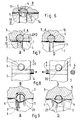
- the assembly according to a first variant of the invention comprises a shaft 1 capable of adjusting in a bore 2 of any part 3; the shaft 1 can thus slide axially from top to bottom (arrows A ) in FIG. 1 or else rotate (arrows B ), around its axis, to the left or to the right.
- the object of the invention is to immobilize the shaft 1 in its bore 2 relative to the part 3 either in rotation or axially or both.
- a cylindrical key 4 is used, mounted without play transversely with respect to the axis of the bore 2 in another bore 5 of the part 3.
- the axis of the key 4 and consequently of the bore 5 is located in a plane perpendicular to the axis of the shaft 1 and it is tangent to one of its generatrices L at a point of intersection 6 shown in FIGS. 1 and 2.
- the rotation of the key 4 for block and unblock shaft 1 in its bore 2 can be make by a knurled button 9 or by a split end 10 ( Figure 2) to cooperate with a screwdriver.
- the circular groove 7 of the shaft 1 is given a profile whose cross section is no longer a semicircle but a half-ellipse whose large diameter corresponds to the width of the groove 7 which is, as in the general variant, equal to the diameter R of the key 4 and whose the small radius r coincides with the depth of the same groove 7.
- the key 4 having its semi-cylindrical part 11 inside the groove 7, provides, as before, complete axial freedom of the shaft 1; conversely, a 180 ° rotation to the left or right of the key 4 causes its semi-cylindrical part 11 towards the inside of the groove 7 of semi-elliptical profile.
- the advantage of this embodiment is that it provides a blocking of the shaft 1 both in translation and in rotation; in addition, such a solution makes it possible to obtain the two blockages simultaneously without the need to act in a particular direction of rotation on the knurled button 9 of the key 4; on the other hand, such a solution only ensures relative blocking in rotation insofar as the contact between the key and the groove is theoretically punctual; this is why, with reference to FIGS. 5, it is proposed an execution of the assembly making it possible to obtain, in addition to the axial blocking of the shaft 1, but also its blocking in rotation by progressive tightening.
- the groove 7 will be machined according to an ovoid profile whose cross section is a continuous curve whose radius centered on the point of tangency 6 varies from one edge 13 of the groove to the other edge 14, between a first value R equal to the radius of the key 4 and a second value r less than R ; we then understand that in its movement, the semi-cylindrical part 11 of the key 4 necessarily driven in the direction of the arrow C in Figure 5b , comes by pivoting around the point of tangency 6 engage first in the groove 7 whose half entry width is equal to the radius R of the key 4; while continuing its movement, the part 11 comes progressively into contact with the wall of the groove 7, the radius of curvature of which decreases continuously up to a value r thus creating a tightening all the more important as the displacement in rotation along C is important .
- the tightening is progressive but requires a drive of the key 4 by its member 9 in one direction C ; drive in the opposite direction is also impossible the edge 14 of the groove 7 forming a
- such a device has the advantage over the previous embodiment of allowing the semi-cylindrical part 11 to slide over 90 ° inside the groove 7, already providing a minimum axial locking of the shaft in its bore. followed in a second step by an increasingly strong counter-tightening of the key 4 according to C (FIG. 6). It is thus possible to position the shaft in two stages, first axially then to make any desired adjustments in rotation and finally block this last movement by continuing the rotation of the key 4 in the same direction.
- any other execution aimed at reducing or enlarging the corner sector of the first blocking phase would not depart from the scope of the invention.
- the key 4 has a recess 8 obtained by a section along a plane parallel to its longitudinal axis which extends on either side of the axis of the shaft 1 over a length at least sufficient so that, when the planar part 15 of the recess 8 is tangent to a generator L of the shaft 1 the latter can be released from its bore 2 (FIG. 7 a ).
- the key 4 can be translated through the part 3 traversed orthogonally by a bore 2 in which comes the shaft 1 which should be left free or interlocked; by an axial movement to the right (FIG. 8 a ) the key (4) blocks the shaft (1) in that a part of said key is incorporated inside the groove 7 of the shaft 1, like what was said in the previous variant, and by an axial displacement to the left it brings a recess 20 opposite the shaft 1, the profile of which is able to match the external shape of said shaft releasing it thus from any contact with the key 4.
- the recess 20 has a shape which can result from a cylindrical milling of radius equal to that of the shaft 1 and of axis perpendicular to that of the key 4 progressing from its surface to a depth sufficient to be able to release said shaft 1 in translation, when the key 4 is in the correct position (FIG. 8 b ).
- the length of the key 4 is greater than the width of the part 3 in which it translates by a value such that, projecting from one side of said part 3 and flush with the other, the recess 20 is or is not in the locking position of the shaft 1 in its bore 2. It is thus possible to have at the projecting end of the key 4 a visual reference by example a color (green, red), or a marking for example a letter ( V , O ), indicating in which stable position is the shaft 1.
- This type of keying with mark on one side and on the other of the key allows a fast and very secure assembly since the colored or marked overflowing part makes it possible to attest that the result is achieved.
- edges 13, 14 of the groove 7 of the shaft 1 are connected to the generators L of the shaft 1 along a curve 21 whose radius or radii of curvature are chosen so that the connection is progressive and without break in continuity.
- the elements constituting the assemblies according to the invention can be made of plastic as well as Plexiglas or any metal allowing the machining to be carried out as described above.
- Assembly according to one or other of the variants or executions as described above is notably applicable to restraint equipment, for example intended for radiotherapy, which requires stalling axially and rotation of many accessories for positioning and repositioning a patient.
Priority Applications (2)
| Application Number | Priority Date | Filing Date | Title |
|---|---|---|---|
| FR9813130A FR2785341A1 (fr) | 1998-10-20 | 1998-10-20 | Dispositif pour l'immobilisation reversible d'un arbre par une clavette tangentielle. |
| EP99403038A EP1106846A1 (de) | 1998-10-20 | 1999-12-06 | Vorrichtung zum reversiblen Blockieren einer Welle anhand von einem tangentialen Verriegelungsstift |
Applications Claiming Priority (2)
| Application Number | Priority Date | Filing Date | Title |
|---|---|---|---|
| FR9813130A FR2785341A1 (fr) | 1998-10-20 | 1998-10-20 | Dispositif pour l'immobilisation reversible d'un arbre par une clavette tangentielle. |
| EP99403038A EP1106846A1 (de) | 1998-10-20 | 1999-12-06 | Vorrichtung zum reversiblen Blockieren einer Welle anhand von einem tangentialen Verriegelungsstift |
Publications (1)
| Publication Number | Publication Date |
|---|---|
| EP1106846A1 true EP1106846A1 (de) | 2001-06-13 |
Family
ID=26153700
Family Applications (1)
| Application Number | Title | Priority Date | Filing Date |
|---|---|---|---|
| EP99403038A Withdrawn EP1106846A1 (de) | 1998-10-20 | 1999-12-06 | Vorrichtung zum reversiblen Blockieren einer Welle anhand von einem tangentialen Verriegelungsstift |
Country Status (2)
| Country | Link |
|---|---|
| EP (1) | EP1106846A1 (de) |
| FR (1) | FR2785341A1 (de) |
Cited By (4)
| Publication number | Priority date | Publication date | Assignee | Title |
|---|---|---|---|---|
| EP1484515A1 (de) * | 2003-06-05 | 2004-12-08 | Maxx Worldwide | Methode zum Verbinden von Kunststoffteilen mit Stabelementen |
| CN101224756B (zh) * | 2008-02-03 | 2010-06-09 | 隆鑫工业有限公司 | 沙滩车的转向节结构 |
| WO2014034593A1 (ja) * | 2012-08-31 | 2014-03-06 | 株式会社ジェイテクト | ロックピン、ロックピン回動工具および連結開放構造 |
| CN105041815A (zh) * | 2014-04-24 | 2015-11-11 | 本田技研工业株式会社 | 无级变速器 |
Families Citing this family (1)
| Publication number | Priority date | Publication date | Assignee | Title |
|---|---|---|---|---|
| DE202007018232U1 (de) * | 2007-12-12 | 2008-03-20 | Terex-Demag Gmbh & Co. Kg | Bolzensicherung |
Citations (6)
| Publication number | Priority date | Publication date | Assignee | Title |
|---|---|---|---|---|
| US3490795A (en) * | 1966-10-15 | 1970-01-20 | Gunther Hennlich | Means for releasable and sealable joining pipes,particularly high pressure lines,with each other or with connector plugs |
| US4309780A (en) * | 1979-10-11 | 1982-01-12 | I.C.S. Cidneo S.P.A. | Toilet seat and cover therefor |
| US4339212A (en) * | 1980-08-25 | 1982-07-13 | Sauber Charles J | Positioning collar |
| EP0541363A1 (de) * | 1991-11-05 | 1993-05-12 | Petroleo Brasileiro S.A. - Petrobras | Durch ein ferngesteuertes Fahrzeug betätigte Einrichtung zum Auswechseln von Führungssäulen |
| CH681967A5 (de) * | 1990-08-21 | 1993-06-30 | Planetron Ag | |
| EP0709327A1 (de) * | 1994-10-28 | 1996-05-01 | Adelino Tomasi | Schnell-Löseendhalterung, insbesondere für Rollenabstützwellen |
Family Cites Families (2)
| Publication number | Priority date | Publication date | Assignee | Title |
|---|---|---|---|---|
| DE3130998C2 (de) * | 1981-08-05 | 1984-03-29 | Montan-Hydraulik GmbH, 4755 Holzwickede | Gewindesicherung |
| DE3706946C2 (de) * | 1987-03-04 | 1995-02-16 | Fraunhofer Ges Forschung | Wechselflansch-Einheit für ein Handhabungsgerät |
-
1998
- 1998-10-20 FR FR9813130A patent/FR2785341A1/fr not_active Withdrawn
-
1999
- 1999-12-06 EP EP99403038A patent/EP1106846A1/de not_active Withdrawn
Patent Citations (6)
| Publication number | Priority date | Publication date | Assignee | Title |
|---|---|---|---|---|
| US3490795A (en) * | 1966-10-15 | 1970-01-20 | Gunther Hennlich | Means for releasable and sealable joining pipes,particularly high pressure lines,with each other or with connector plugs |
| US4309780A (en) * | 1979-10-11 | 1982-01-12 | I.C.S. Cidneo S.P.A. | Toilet seat and cover therefor |
| US4339212A (en) * | 1980-08-25 | 1982-07-13 | Sauber Charles J | Positioning collar |
| CH681967A5 (de) * | 1990-08-21 | 1993-06-30 | Planetron Ag | |
| EP0541363A1 (de) * | 1991-11-05 | 1993-05-12 | Petroleo Brasileiro S.A. - Petrobras | Durch ein ferngesteuertes Fahrzeug betätigte Einrichtung zum Auswechseln von Führungssäulen |
| EP0709327A1 (de) * | 1994-10-28 | 1996-05-01 | Adelino Tomasi | Schnell-Löseendhalterung, insbesondere für Rollenabstützwellen |
Cited By (4)
| Publication number | Priority date | Publication date | Assignee | Title |
|---|---|---|---|---|
| EP1484515A1 (de) * | 2003-06-05 | 2004-12-08 | Maxx Worldwide | Methode zum Verbinden von Kunststoffteilen mit Stabelementen |
| CN101224756B (zh) * | 2008-02-03 | 2010-06-09 | 隆鑫工业有限公司 | 沙滩车的转向节结构 |
| WO2014034593A1 (ja) * | 2012-08-31 | 2014-03-06 | 株式会社ジェイテクト | ロックピン、ロックピン回動工具および連結開放構造 |
| CN105041815A (zh) * | 2014-04-24 | 2015-11-11 | 本田技研工业株式会社 | 无级变速器 |
Also Published As
| Publication number | Publication date |
|---|---|
| FR2785341A1 (fr) | 2000-05-05 |
Similar Documents
| Publication | Publication Date | Title |
|---|---|---|
| EP0963498B2 (de) | Verschlussvorrichtung für eine tür | |
| EP0712667B1 (de) | Zentrifuge mit abnehmbarem Rotor und einer Einrichtung zur axialen Verriegelung des Rotors auf der Antriebswelle | |
| EP0793024B1 (de) | Verbindungs- und Verriegelungsvorrichtung für teleskopische Rohre | |
| WO2007132133A1 (fr) | Système de verrouillage d'un premier arbre par rapport à un deuxième arbre supprimant les jeux entre lesdits arbres | |
| FR2748513A1 (fr) | Verrou a debrayage axial pour un mecanisme de serrure de vehicule automobile | |
| EP1896303A1 (de) | Mittel zur befestigung eines antriebsmechanismus einer wischervorrichtung an einem körpergehäuseelement | |
| FR2478227A1 (fr) | Dispositif d'assemblage de deux composants de meubles, appliques perpendiculairement l'un contre l'autre | |
| FR2487275A1 (fr) | Dispositif antivol pour vehicules automobiles | |
| EP0263769B1 (de) | Tür- oder Fensterscharnier mit axialer Blockierung des Bolzens | |
| WO2008053263A1 (fr) | Dispositif autobloquant et article de joaillerie comportant ledit dispositif | |
| FR3032756A1 (de) | ||
| EP1106846A1 (de) | Vorrichtung zum reversiblen Blockieren einer Welle anhand von einem tangentialen Verriegelungsstift | |
| FR3011195A3 (de) | ||
| EP1391361A1 (de) | Verbindungsvorrichtung für eine Betätigungsstange eines Bremskraftverstärkers | |
| EP0943758B1 (de) | Axial entkuppelndes Schloss für ein Schlossmechanismus eines Personenkraftwagens | |
| EP2173953B1 (de) | Verbindungsvorrichtung zur herstellung einer verbindung zwischen dem türriegel und dem türverschluss eines motorfahrzeugs | |
| EP2078806B1 (de) | Schliesszylinder mit zylindrischer Zuhaltescheibenanordnung | |
| FR2711221A1 (fr) | Dispositif pour immobiliser en rotation et sans jeu une vis de réglage d'un réflecteur de projecteur. | |
| FR2802234A1 (fr) | Barillet de surete muni d'un moyen anti-crochetage | |
| FR2802233A1 (fr) | Barillet de surete muni d'un moyen anti-vibreur | |
| FR2699969A1 (fr) | Dispositif de blocage. | |
| FR2886703A1 (fr) | Boite de vitesses comprenant une rondelle d'appui solidaire d'un arbre en rotation | |
| EP1722929B1 (de) | Greifklemmende für eine schraubvorrichtung | |
| FR2705077A1 (fr) | Dispositif antivol pour motocycle. | |
| EP1164236A1 (de) | Elektronischer Schlüssel mit herausklappbarem Einsatz |
Legal Events
| Date | Code | Title | Description |
|---|---|---|---|
| PUAI | Public reference made under article 153(3) epc to a published international application that has entered the european phase |
Free format text: ORIGINAL CODE: 0009012 |
|
| AK | Designated contracting states |
Kind code of ref document: A1 Designated state(s): AT BE CH CY DE DK ES FI FR GB GR IE IT LI LU MC NL PT SE |
|
| AX | Request for extension of the european patent |
Free format text: AL;LT;LV;MK;RO;SI |
|
| 17P | Request for examination filed |
Effective date: 20010625 |
|
| AKX | Designation fees paid |
Free format text: AT BE CH CY DE DK ES FI FR GB GR IE IT LI LU MC NL PT SE |
|
| STAA | Information on the status of an ep patent application or granted ep patent |
Free format text: STATUS: THE APPLICATION IS DEEMED TO BE WITHDRAWN |
|
| 18D | Application deemed to be withdrawn |
Effective date: 20060701 |