EP1722929B1 - Greifklemmende für eine schraubvorrichtung - Google Patents
Greifklemmende für eine schraubvorrichtung Download PDFInfo
- Publication number
- EP1722929B1 EP1722929B1 EP04718985A EP04718985A EP1722929B1 EP 1722929 B1 EP1722929 B1 EP 1722929B1 EP 04718985 A EP04718985 A EP 04718985A EP 04718985 A EP04718985 A EP 04718985A EP 1722929 B1 EP1722929 B1 EP 1722929B1
- Authority
- EP
- European Patent Office
- Prior art keywords
- jaws
- screw
- bushing
- head
- end fitting
- Prior art date
- Legal status (The legal status is an assumption and is not a legal conclusion. Google has not performed a legal analysis and makes no representation as to the accuracy of the status listed.)
- Expired - Lifetime
Links
- 230000000694 effects Effects 0.000 claims description 5
- 230000002093 peripheral effect Effects 0.000 claims description 5
- 230000000717 retained effect Effects 0.000 claims description 5
- 230000008878 coupling Effects 0.000 claims 1
- 238000010168 coupling process Methods 0.000 claims 1
- 238000005859 coupling reaction Methods 0.000 claims 1
- 230000003993 interaction Effects 0.000 abstract 1
- 241000735470 Juncus Species 0.000 description 3
- 230000005540 biological transmission Effects 0.000 description 2
- 230000000295 complement effect Effects 0.000 description 2
- 239000000243 solution Substances 0.000 description 2
- 241001417935 Platycephalidae Species 0.000 description 1
- 240000008042 Zea mays Species 0.000 description 1
- 210000000078 claw Anatomy 0.000 description 1
- 238000010273 cold forging Methods 0.000 description 1
- 238000006073 displacement reaction Methods 0.000 description 1
- 230000005489 elastic deformation Effects 0.000 description 1
- 239000011381 foam concrete Substances 0.000 description 1
- -1 for example Substances 0.000 description 1
- 238000007373 indentation Methods 0.000 description 1
- 238000002347 injection Methods 0.000 description 1
- 239000007924 injection Substances 0.000 description 1
- 230000014759 maintenance of location Effects 0.000 description 1
- 239000000463 material Substances 0.000 description 1
- 238000009527 percussion Methods 0.000 description 1
- 238000005096 rolling process Methods 0.000 description 1
- 238000010079 rubber tapping Methods 0.000 description 1
Images


Classifications
-
- B—PERFORMING OPERATIONS; TRANSPORTING
- B25—HAND TOOLS; PORTABLE POWER-DRIVEN TOOLS; MANIPULATORS
- B25B—TOOLS OR BENCH DEVICES NOT OTHERWISE PROVIDED FOR, FOR FASTENING, CONNECTING, DISENGAGING OR HOLDING
- B25B23/00—Details of, or accessories for, spanners, wrenches, screwdrivers
- B25B23/02—Arrangements for handling screws or nuts
- B25B23/08—Arrangements for handling screws or nuts for holding or positioning screw or nut prior to or during its rotation
- B25B23/10—Arrangements for handling screws or nuts for holding or positioning screw or nut prior to or during its rotation using mechanical gripping means
-
- B—PERFORMING OPERATIONS; TRANSPORTING
- B25—HAND TOOLS; PORTABLE POWER-DRIVEN TOOLS; MANIPULATORS
- B25B—TOOLS OR BENCH DEVICES NOT OTHERWISE PROVIDED FOR, FOR FASTENING, CONNECTING, DISENGAGING OR HOLDING
- B25B13/00—Spanners; Wrenches
- B25B13/44—Spanners; Wrenches of the chuck type
-
- F—MECHANICAL ENGINEERING; LIGHTING; HEATING; WEAPONS; BLASTING
- F16—ENGINEERING ELEMENTS AND UNITS; GENERAL MEASURES FOR PRODUCING AND MAINTAINING EFFECTIVE FUNCTIONING OF MACHINES OR INSTALLATIONS; THERMAL INSULATION IN GENERAL
- F16B—DEVICES FOR FASTENING OR SECURING CONSTRUCTIONAL ELEMENTS OR MACHINE PARTS TOGETHER, e.g. NAILS, BOLTS, CIRCLIPS, CLAMPS, CLIPS OR WEDGES; JOINTS OR JOINTING
- F16B23/00—Specially shaped nuts or heads of bolts or screws for rotations by a tool
- F16B23/0061—Specially shaped nuts or heads of bolts or screws for rotations by a tool with grooves, notches or splines on the external peripheral surface designed for tools engaging in radial direction
Definitions
- the present invention relates to a gripping and screwing end for fitting a screwing device such as, for example, a motorized screwdriver / unscrewer.
- a gripping and screwing tip as described in the preamble of claim 1 is known from the prior art for example by the document EP 1 382 418 .
- screws that can have multiple shapes and particularly, but not exclusively, to screws whose head has at its periphery conformations intended to cooperate with a screwing tool to exert on the screw a screwing torque and a cylindrical sub-head portion whose diameter is smaller than that of the head but greater than that of the threaded rod of the screw.
- This type of screw is specially designed for a screwdriver comprising a bush capable of being rotated and having, at one of its ends, a coaxial cavity opening outwardly so as to be able to receive the head of the opinion.
- the inner surface of the sleeve defining this cavity has conformations adapted to engage with that of the head of the screw, so as to ensure the transmission of the torque screw.
- This endpiece is provided with gripping means which engage in the space between the two shoulders, during the introduction of the head of the screw inside the end piece until it comes into abutment against the portion cylindrical sub-head at the end of engagement.
- the rotational drive function is provided separately from the gripping function.
- the gripping means which no longer have a rotational drive function can have reduced dimensions without losing efficiency.
- the centering means can be provided both by the bushing and by the gripping means: This arrangement makes it possible to use screws with relatively flat heads which might slightly swivel in a conventional screwdriver bit.
- the action of the gripping means on the cylindrical sub-head confirms this centering at the end of introduction of the screw into the socket.
- the core successively comprises a cylindrical front portion, a cylindrical central portion of smaller diameter and a rear portion flaring rearwardly so as to form a ramp.
- the jaws have, in the vicinity of their rear end, an outer face provided with a groove in which engages an elastic ring and an oblique inner face intended to cooperate with the rear part of the core of so as to provoke, during an axial displacement of the jaws towards the rear, a tilting of the jaws causing their closure.
- the invention therefore more particularly aims to overcome this disadvantage so as to ensure better retention of both small screws and screws having a significant length.
- a tip for gripping and screwing a screw comprising a socket having, at one of its ends, a coaxial cavity and a fixed coaxial core with respect to the socket which extends coaxially with said cavity by delimiting therewith a substantially cylindrical anterior volume within which the head of the screw can be introduced and an annular volume in which are mounted axially mobile jaws provided with elements of gripping which engage in the anterior volume of the socket.
- the jaws are pivotally mounted and retained axially on a tubular sleeve by means of articulation means, this tubular sleeve being axially movable on the core so as to be able to move from a forward end position in which the jaws are in the deployed state under the effect of elastic means at a rear end position in which the jaws are brought and held in closed position by the cooperation of a jaw conformation with a suitable conformation of the sleeve or the core which causes the jaws to tilt around the hinge means, the return to the end position of the front race of the sleeve then causing the passage of the jaws in the open position.
- the jaws may consist of rods having, in their front part, a notch in which the peripheral edge of the head of the screw can engage in the closed position and, in the vicinity of their rear end, an outer face provided with of a groove in which an elastic ring engages.
- the outer face of these jaws may comprise, preferably in its anterior part, an oblique portion relative to the longitudinal axis of the tip, this oblique portion constituting a ramp cooperating with the front edge of the orifice of the sleeve for cause the jaws to tilt in the closed position.
- the sleeve may advantageously comprise, in the bottom of the cavity, an annular flare in which the ring may partially engage after elastic deformation to lock the movable assembly constituted by the tubular sleeve and the jaws in the rear end position, the jaws then being in the closed position. Unlocking is then obtained only by exerting on the jaws an axial traction of sufficient amplitude so that the ring, by deforming elastically, can escape the flare.
- the core may, for its part, have a stepped cylindrical shape comprising a cylindrical portion on which the tubular sleeve slides, this cylindrical portion being limited, on one side, by a shoulder which constitutes the bottom of the cavity and, on the other side, by a cylindrical portion of larger diameter (which may consist of the head of a screw coming from screw into a tapped axial bore made in the core).
- the inner surface of the sleeve may comprise conformations capable of coming into contact with corresponding conformations of the head of the screw that is to be screwed.
- This surface may further comprise axial grooves for guiding the jaws.
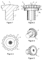
- This screw head 1 has a convex upper face 2 with the center of an injection bowl 3. The presence of this bowl exists only in the case where the head is overmolded. By cons, in the case of a cold forging (rolling), the upper face of the head will be continuously curved.
- the peripheral edge 4 of the head 1 is serrated and here comprises fifteen teeth 5 separated by notches 6 forming an angle of about 120 °.
- This head 1 is connected to a coaxial rod 7 via a cylindrical sub-head portion 8 whose diameter is substantially equal to the distance between the bottom of the notches and the axis X, X 'of the screw.
- the height of the cylindrical portion 8 is substantially equal to the height of the edge 4 device of the head 1.
- the diameter of the rod 7 of the screw, at its connection to the cylindrical portion 8, is much smaller than that of the head 1 (about 50%), the connection between the cylindrical portion 8 with the peripheral edge 4 of the head 1 and with the end of the rod 7, taking place by means of radial shoulders R 1 , R 2 .
- this screw can be screwed using a hand tool having a tubular nozzle whose inner profile corresponds to the outer serrated form of the head 1.
- the screwdriver tip illustrated on the Figures 6 to 14 which essentially comprises a tubular bushing 10 closed on one side by a circular base 11 integral with a coaxial rod 12 partially hexagonal in section, intended to engage in the mandrel of a screwdriver.
- the bottom 11 has a circular shape and comprises, at its periphery, three jaws 13 to 120 ° from one another which extend radially projecting.
- the outside diameter of the bottom 11 is substantially equal to the inside diameter of the sleeve 10.
- the bushing 10 comprises three axial grooves G 1 to G 3 at 120 ° to each other in which the claws 13 engage respectively.
- the core 15 has a cylindrical shape and is provided with a coaxial threaded bore in which a screw 26 is screwed in, the cylindrical head 27 of which has a diameter greater than that of the cylindrical shape of the core 15.
- the tubular sleeve 19 comprises, meanwhile, an inner surface having a stepped cylindrical shape, a first portion 28 (posterior) has a diameter substantially equal to that of the shape cylindrical core 15 while a second portion 29 (anterior) has a diameter substantially equal to the diameter of the head of the screw 26.
- this tubular sleeve 19 comprises, starting from its anterior face, a collar 30 followed by a first substantially cylindrical portion 31, a second cylindrical portion of smaller diameter than the first provided with an annular protrusion 33 and, finally, a posterior cylindrical portion 34 of larger diameter, provided with an annular groove 35 and divided into three sectors by three respective axial notches 36 with an oblique bottom converging towards the axis of the nozzle, in the direction of its posterior end.
- the jaws M 1 to M 3 engage the tubular sleeve, at 120 ° from each other, in a position in which their posterior parts engage in a respective notch 36 while the annular protrusion of the sleeve 33 engages in their notches 21 ( figure 10 ) thus producing a hinge allowing the jaws M 1 to M 3 to tilt in axial planes while being retained axially on the tubular sleeve 19. This tilting is authorized due to the clearances of the funds of the indentations 36.
- the inner face of the sleeve 10 comprises, in the vicinity of the bottom, an annular groove G into which the ring 24 engages when the tubular sleeve 19 is in the end position back stroke.
- the ends of the jaws M 1 to M 3 emerge from the sleeve 10 and are oriented radially outwardly so that the notches 20 are spaced apart sufficiently to receive the head 1 of the screw.
- the collar 30 located at the front end of the tubular sleeve 19 is then in front of the head 1 of the screw V.
- the traction exerted by the screw causes the moving assembly to move forward with simultaneous opening of the jaws M 1 to M 3 under the effect of the action of the elastic ring 24.
- the head 1 of the screw can be disengaged from the jaws M 1 to M 3 .
- this tip can be used in particular for screwing self-piercing percussion screws in a material such as, for example, cellular concrete.
- the tip can be easily adapted for screwing a screw 35, the head 36 has, at its periphery, a circular edge and, in its central portion, a recess 37 (for example cruciform) allowing its driving in rotation.
- the head 36 has, at its periphery, a circular edge and, in its central portion, a recess 37 (for example cruciform) allowing its driving in rotation.
- the screw 38 provided at the end of the core may comprise a head having a shape complementary to that of the convex footprint 37 of the screw 35; the sleeve 10 will present a smooth profile instead of the serrated profile and the notch of the jaws M 1 to M 3 will have a conical portion adapted to engage with the conical face sub-head of the screw 35 ( figure 15 ).
Landscapes
- Engineering & Computer Science (AREA)
- Mechanical Engineering (AREA)
- Dowels (AREA)
- Gripping Jigs, Holding Jigs, And Positioning Jigs (AREA)
- Hand Tools For Fitting Together And Separating, Or Other Hand Tools (AREA)
- Load-Engaging Elements For Cranes (AREA)
- Manipulator (AREA)
- Details Of Spanners, Wrenches, And Screw Drivers And Accessories (AREA)
- Clamps And Clips (AREA)
Claims (10)
- Greif- und Verschraubungsaufsatz für eine Schraube (1) umfassend eine Hülse (10), die, an einem ihrer Enden, einen koaxialen Hohlraum und einen bezüglich der Hülse (10) unbeweglichen koaxialen Kern (15) aufweist, der sich koaxial zu dem Hohlraum erstreckt und mit diesem ein vorausgehendes, im Wesentlichen zylindrisches Volumen (16) begrenzt, in dessen Inneres sich der Kopf der Schraube (1) einschieben kann, und ein ringförmiges Volumen (18), in dem axial bewegliche Backen (M1 bis M3) montiert sind, die mit Greifelementen versehen sind, die in das vorausgehende Volumen (16) der Hülse (10) eingreifen,
dadurch gekennzeichnet, dass die Backen (M1 bis M3) klappbar und axial aufgesetzt auf eine röhrenförmigen Manschette (19) mit Hilfe von Dreheinrichtungen (33) montiert sind, wobei diese röhrenförmige Manschette (19) auf dem Kern (15) axial beweglich ist, derart, dass sie von einer Vorwärtslauf-Endposition, in der sich die Backen (M1 bis M3) unter der Wirkung von elastischen Mitteln (24) im ausgefahrenen Zustand befinden, in eine Rückwärtslauf-Endposition übergehen können, in der die Backen (M1 bis M3) in Position gebracht sind und, mit Hilfe des Zusammenwirkens einer Ausgestaltung der Backen (M1 bis M3) mit einer geeigneten Ausgestaltung der Hülse (10) oder des Kerns (15), der das Ausklappen der Backen (M1 bis M3) um die Gelenkeinrichtungen (33) auslöst, in geschlossener Position gehalten werden, wobei die Rückkehr in die Vorwärtslauf-Endposition der Manschette (19) anschließend den Übergang der Backen in die geöffnete Position herbeiführt. - Aufsatz nach Anspruch 1,
dadurch gekennzeichnet, dass die Backen (M1 bis M3) aus Stiften bestehen, die in ihrem vorderen Teil eine Aussparung (20), in die der Umfangsrand des Kopfes der Schraube (1) in der geschlossenen Position zum Eingriff kommen kann, und nahe an ihrem rückwärtigen Ende eine Außenfläche, die mit einer Vertiefung (23) versehen ist, in die ein elastischer Ring (24) eingreift, aufweisen. - Aufsatz nach einem der Ansprüche 1 und 2,
dadurch gekennzeichnet, dass die Außenfläche der Backen (M1 bis M3) in ihrem vorderen Teil einen bezüglich der Längsachse des Kopfes schrägen Teil (22) umfasst, wobei dieser schräge Teil (22) eine Rampe aufbaut, die mit dem vorderen Rand der Öffnung der Hülse (10) zusammenwirken, um das Ausklappen der Backen (M1 bis M3) in die geschlossene Position herbeizuführen. - Aufsatz nach einem der vorhergehenden Ansprüche,
dadurch gekennzeichnet, dass die Hülse (10) im Boden des Hohlraums eine ringförmige Erweiterung (G) beinhaltet, in die der Ring (24) nach elastischer Verformung teilweise eingreifen kann, um die bewegliche Gesamtheit bestehend aus der röhrenförmigen Manschette (19) und den Backen (M1 bis M3) in der Rückwärtslauf-Endposition zu verriegeln, wobei die Backen (M1 bis M3) sich nun in der geschlossenen Position befinden, wobei die Entriegelung erst erhalten wird, wenn auf die Backen (M1 bis M3) ein axialer Zug mit einer Amplitude ausgeübt wird, die ausreicht, damit der Ring (24) unter elastischer Verformung aus der Aussparung G herausspringen kann. - Aufsatz nach einem der vorhergehenden Ansprüche,
dadurch gekennzeichnet, dass der Kern (15) eine abgestufte zylindrische Form aufweist, die einen zylindrischen Teil (31) beinhaltet, auf dem die röhrenförmige Manschette (19) gleitet, wobei dieser zylindrische Teil (31) von einer Seite durch eine Schulter, die den Boden (11) des Hohlraums aufbaut, und von der anderen Seite durch einen zylindrischen Teil von größerem Durchmesser (27) begrenzt ist. - Aufsatz nach Anspruch 5,
dadurch gekennzeichnet, dass der Teil von größerem Durchmesser (27) aus dem Kopf einer Schraube (26) besteht, die sich in die axiale Gewindebohrung schraubt, die in dem Kern (15) realisiert ist. - Aufsatz nach einem der vorhergehenden Ansprüche,
dadurch gekennzeichnet, dass die Innenfläche der Hülse (10) Ausgestaltungen (17) beinhaltet, die dazu geeignet sind, mit den entsprechenden Ausgestaltungen der Kopfes der Schraube (1), die man einzuschrauben wünscht, in Eingriff zu kommen. - Aufsatz nach einem der vorhergehenden Ansprüche,
dadurch gekennzeichnet, dass die Innenfläche der Hülse (10) axiale Rillen beinhaltet, die zur Führung der Backen (M1 bis M3) dienen. - Aufsatz nach Anspruch 8,
dadurch gekennzeichnet, dass die Hülse (10) von der einen Seite durch einen Boden (11) verschlossen ist, der mit einem koaxialen Stab (12) aus einem Stück besteht, der dazu bestimmt ist, in den Dorn eines Schraubers einzugreifen, wobei dieser Boden Klauen beinhaltet, die in die oben genannten Rillen eingreifen. - Aufsatz nach einem Anspruch 5,
dadurch gekennzeichnet, dass der Teil von größerem Durchmesser des Kerns (15) so ausgestaltet ist, dass er mit einem Stempel (37) in Eingriff kommt, der auf dem Kopf von Schraube (35) ausgebildet ist.
Applications Claiming Priority (1)
| Application Number | Priority Date | Filing Date | Title |
|---|---|---|---|
| PCT/FR2004/000566 WO2005097410A1 (fr) | 2004-03-10 | 2004-03-10 | Embout de prehension et de serrage destine a eouiper un appareil de vissage. |
Publications (2)
| Publication Number | Publication Date |
|---|---|
| EP1722929A1 EP1722929A1 (de) | 2006-11-22 |
| EP1722929B1 true EP1722929B1 (de) | 2009-04-29 |
Family
ID=34957646
Family Applications (1)
| Application Number | Title | Priority Date | Filing Date |
|---|---|---|---|
| EP04718985A Expired - Lifetime EP1722929B1 (de) | 2004-03-10 | 2004-03-10 | Greifklemmende für eine schraubvorrichtung |
Country Status (6)
| Country | Link |
|---|---|
| EP (1) | EP1722929B1 (de) |
| AT (1) | ATE429998T1 (de) |
| DE (1) | DE602004020929D1 (de) |
| ES (1) | ES2325262T3 (de) |
| PT (1) | PT1722929E (de) |
| WO (1) | WO2005097410A1 (de) |
Families Citing this family (2)
| Publication number | Priority date | Publication date | Assignee | Title |
|---|---|---|---|---|
| DE202014103714U1 (de) | 2014-08-11 | 2015-11-12 | Wera-Werk Hermann Werner Gmbh & Co. Kg | An einer Umfangsfläche eines Schraubenkopfes drehmomentübertragend angreifende Schraubvorrichtung |
| CN118436415B (zh) * | 2024-07-08 | 2024-09-10 | 泓欣科创生物科技(北京)有限公司 | 骨固定装置 |
Family Cites Families (5)
| Publication number | Priority date | Publication date | Assignee | Title |
|---|---|---|---|---|
| US3379231A (en) * | 1966-11-29 | 1968-04-23 | John Gallo Sr. | Fastener holder and driver |
| US3758938A (en) * | 1971-11-03 | 1973-09-18 | Cooper Ind Inc | Tool for applying and locking threaded fasteners and method |
| DE19650799C1 (de) * | 1996-12-06 | 1998-07-02 | Sfs Ind Holding Ag | Nuß zur Aufnahme eines oder zum Einsetzen in einen Befestigerkopf(es) |
| DE19712783C2 (de) * | 1997-03-26 | 2000-11-09 | Sfs Ind Holding Ag Heerbrugg | Schrauberelement |
| FR2842447B1 (fr) * | 2002-07-19 | 2005-02-25 | Etanco L R | Embout de prehension et de vissage pour vis a tete speciale. |
-
2004
- 2004-03-10 ES ES04718985T patent/ES2325262T3/es not_active Expired - Lifetime
- 2004-03-10 AT AT04718985T patent/ATE429998T1/de not_active IP Right Cessation
- 2004-03-10 PT PT04718985T patent/PT1722929E/pt unknown
- 2004-03-10 WO PCT/FR2004/000566 patent/WO2005097410A1/fr not_active Application Discontinuation
- 2004-03-10 EP EP04718985A patent/EP1722929B1/de not_active Expired - Lifetime
- 2004-03-10 DE DE602004020929T patent/DE602004020929D1/de not_active Expired - Lifetime
Also Published As
| Publication number | Publication date |
|---|---|
| EP1722929A1 (de) | 2006-11-22 |
| WO2005097410A1 (fr) | 2005-10-20 |
| ATE429998T1 (de) | 2009-05-15 |
| ES2325262T3 (es) | 2009-08-31 |
| PT1722929E (pt) | 2009-06-26 |
| DE602004020929D1 (de) | 2009-06-10 |
Similar Documents
| Publication | Publication Date | Title |
|---|---|---|
| EP3539685B1 (de) | Werkzeug und verfahren zum setzen einer blindbefestigung | |
| EP1419837B1 (de) | Werkzeughalter mit Verriegelungssystem | |
| FR2761127A1 (fr) | Article a fixer en aveugle et vehicule le comportant | |
| EP2389264B1 (de) | Werkzeugspannfutter zum vorsehen an einer rotierenden maschine | |
| EP1118401B1 (de) | Aufweitungsvorrichtung zum Formen von Muffen an Rohrenden | |
| FR2540772A1 (fr) | Outil automatique de vissage de goujons | |
| FR2465569A1 (fr) | Manche tubulaire rond pour outils domestiques | |
| EP1553310B1 (de) | Vorrichtung zur lösbaren Verriegelung eines Endstückes auf einer Struktur mit verstellbarer Position | |
| WO1995029041A1 (fr) | Outil de serrage, notamment tournevis | |
| EP1722929B1 (de) | Greifklemmende für eine schraubvorrichtung | |
| EP3471919B1 (de) | Verfahren und schnell lösbares einstellwerkzeug für ein zu crimpendes element | |
| EP2265411B1 (de) | Greif- und schraubeinsatz für eine schraubvorrichtung | |
| FR2975323A1 (fr) | Dispositif pour l'extraction de bague | |
| EP1382418A1 (de) | Screwing device including a screw with a special head and a socket adapted to this head | |
| EP1382863B1 (de) | Schraube mit einem insbesondere einem Einsatz zum Aufnehmen und Anziehen derselben geeigneten Kopfes | |
| EP0618045A1 (de) | Bandschlüssel, insbesondere für Fahrzeug-Ölfilter | |
| CA2075962C (fr) | Procede de rivetage de materiaux au moyen d'un rivet aveugle et rivets aveugles correspondants | |
| FR2843062A1 (fr) | Embout de prehension et de vissage utilisable sur un appareil de vissage. | |
| FR2785341A1 (fr) | Dispositif pour l'immobilisation reversible d'un arbre par une clavette tangentielle. | |
| FR3039448A1 (fr) | Douille de vissage magnetique. | |
| FR2946383A1 (fr) | Butee reglable. | |
| FR2883210A1 (fr) | Mandrin porte-outil pour l'equipement d'une machine tournante | |
| EP1873406A1 (de) | Bördelmutter | |
| WO2006030083A1 (fr) | Dispositif pour la pose et le vissage d'un element de fixation d’un revetement d'isolation thermique sur une structure support | |
| FR3039784A1 (fr) | Douille de vissage a billes. |
Legal Events
| Date | Code | Title | Description |
|---|---|---|---|
| PUAI | Public reference made under article 153(3) epc to a published international application that has entered the european phase |
Free format text: ORIGINAL CODE: 0009012 |
|
| 17P | Request for examination filed |
Effective date: 20060829 |
|
| AK | Designated contracting states |
Kind code of ref document: A1 Designated state(s): AT BE BG CH CY CZ DE DK EE ES FI FR GB GR HU IE IT LI LU MC NL PL PT RO SE SI SK TR |
|
| DAX | Request for extension of the european patent (deleted) | ||
| GRAP | Despatch of communication of intention to grant a patent |
Free format text: ORIGINAL CODE: EPIDOSNIGR1 |
|
| GRAP | Despatch of communication of intention to grant a patent |
Free format text: ORIGINAL CODE: EPIDOSNIGR1 |
|
| RAP1 | Party data changed (applicant data changed or rights of an application transferred) |
Owner name: LR ETANCO |
|
| GRAS | Grant fee paid |
Free format text: ORIGINAL CODE: EPIDOSNIGR3 |
|
| GRAA | (expected) grant |
Free format text: ORIGINAL CODE: 0009210 |
|
| RAP1 | Party data changed (applicant data changed or rights of an application transferred) |
Owner name: ATELIERS LR ETANCO |
|
| AK | Designated contracting states |
Kind code of ref document: B1 Designated state(s): AT BE BG CH CY CZ DE DK EE ES FI FR GB GR HU IE IT LI LU MC NL PL PT RO SE SI SK TR |
|
| REG | Reference to a national code |
Ref country code: GB Ref legal event code: FG4D Free format text: NOT ENGLISH |
|
| REG | Reference to a national code |
Ref country code: CH Ref legal event code: EP |
|
| REG | Reference to a national code |
Ref country code: RO Ref legal event code: EPE |
|
| REF | Corresponds to: |
Ref document number: 602004020929 Country of ref document: DE Date of ref document: 20090610 Kind code of ref document: P |
|
| REG | Reference to a national code |
Ref country code: IE Ref legal event code: FG4D |
|
| REG | Reference to a national code |
Ref country code: PT Ref legal event code: SC4A Free format text: AVAILABILITY OF NATIONAL TRANSLATION Effective date: 20090619 |
|
| REG | Reference to a national code |
Ref country code: CH Ref legal event code: NV Representative=s name: CABINET MOUTARD |
|
| REG | Reference to a national code |
Ref country code: ES Ref legal event code: FG2A Ref document number: 2325262 Country of ref document: ES Kind code of ref document: T3 |
|
| PG25 | Lapsed in a contracting state [announced via postgrant information from national office to epo] |
Ref country code: FI Free format text: LAPSE BECAUSE OF FAILURE TO SUBMIT A TRANSLATION OF THE DESCRIPTION OR TO PAY THE FEE WITHIN THE PRESCRIBED TIME-LIMIT Effective date: 20090429 Ref country code: AT Free format text: LAPSE BECAUSE OF FAILURE TO SUBMIT A TRANSLATION OF THE DESCRIPTION OR TO PAY THE FEE WITHIN THE PRESCRIBED TIME-LIMIT Effective date: 20090429 |
|
| PG25 | Lapsed in a contracting state [announced via postgrant information from national office to epo] |
Ref country code: SE Free format text: LAPSE BECAUSE OF FAILURE TO SUBMIT A TRANSLATION OF THE DESCRIPTION OR TO PAY THE FEE WITHIN THE PRESCRIBED TIME-LIMIT Effective date: 20090729 Ref country code: SI Free format text: LAPSE BECAUSE OF FAILURE TO SUBMIT A TRANSLATION OF THE DESCRIPTION OR TO PAY THE FEE WITHIN THE PRESCRIBED TIME-LIMIT Effective date: 20090429 Ref country code: PL Free format text: LAPSE BECAUSE OF FAILURE TO SUBMIT A TRANSLATION OF THE DESCRIPTION OR TO PAY THE FEE WITHIN THE PRESCRIBED TIME-LIMIT Effective date: 20090429 |
|
| REG | Reference to a national code |
Ref country code: IE Ref legal event code: FD4D |
|
| PG25 | Lapsed in a contracting state [announced via postgrant information from national office to epo] |
Ref country code: DK Free format text: LAPSE BECAUSE OF FAILURE TO SUBMIT A TRANSLATION OF THE DESCRIPTION OR TO PAY THE FEE WITHIN THE PRESCRIBED TIME-LIMIT Effective date: 20090429 Ref country code: EE Free format text: LAPSE BECAUSE OF FAILURE TO SUBMIT A TRANSLATION OF THE DESCRIPTION OR TO PAY THE FEE WITHIN THE PRESCRIBED TIME-LIMIT Effective date: 20090429 Ref country code: IE Free format text: LAPSE BECAUSE OF FAILURE TO SUBMIT A TRANSLATION OF THE DESCRIPTION OR TO PAY THE FEE WITHIN THE PRESCRIBED TIME-LIMIT Effective date: 20090429 |
|
| PLBE | No opposition filed within time limit |
Free format text: ORIGINAL CODE: 0009261 |
|
| STAA | Information on the status of an ep patent application or granted ep patent |
Free format text: STATUS: NO OPPOSITION FILED WITHIN TIME LIMIT |
|
| PG25 | Lapsed in a contracting state [announced via postgrant information from national office to epo] |
Ref country code: BG Free format text: LAPSE BECAUSE OF FAILURE TO SUBMIT A TRANSLATION OF THE DESCRIPTION OR TO PAY THE FEE WITHIN THE PRESCRIBED TIME-LIMIT Effective date: 20090729 |
|
| 26N | No opposition filed |
Effective date: 20100201 |
|
| PG25 | Lapsed in a contracting state [announced via postgrant information from national office to epo] |
Ref country code: GR Free format text: LAPSE BECAUSE OF FAILURE TO SUBMIT A TRANSLATION OF THE DESCRIPTION OR TO PAY THE FEE WITHIN THE PRESCRIBED TIME-LIMIT Effective date: 20090730 Ref country code: MC Free format text: LAPSE BECAUSE OF NON-PAYMENT OF DUE FEES Effective date: 20100331 |
|
| GBPC | Gb: european patent ceased through non-payment of renewal fee |
Effective date: 20100310 |
|
| PG25 | Lapsed in a contracting state [announced via postgrant information from national office to epo] |
Ref country code: GB Free format text: LAPSE BECAUSE OF NON-PAYMENT OF DUE FEES Effective date: 20100310 |
|
| REG | Reference to a national code |
Ref country code: CH Ref legal event code: PFA Owner name: ATELIERS LR ETANCO Free format text: ATELIERS LR ETANCO#PARC LES ERABLES - BATIMENT 1 66 ROUTE DE SARTROUVILLE#78230 LE PECQ (FR) -TRANSFER TO- ATELIERS LR ETANCO#PARC LES ERABLES - BATIMENT 1 66 ROUTE DE SARTROUVILLE#78230 LE PECQ (FR) |
|
| PG25 | Lapsed in a contracting state [announced via postgrant information from national office to epo] |
Ref country code: CY Free format text: LAPSE BECAUSE OF FAILURE TO SUBMIT A TRANSLATION OF THE DESCRIPTION OR TO PAY THE FEE WITHIN THE PRESCRIBED TIME-LIMIT Effective date: 20090429 |
|
| PG25 | Lapsed in a contracting state [announced via postgrant information from national office to epo] |
Ref country code: HU Free format text: LAPSE BECAUSE OF FAILURE TO SUBMIT A TRANSLATION OF THE DESCRIPTION OR TO PAY THE FEE WITHIN THE PRESCRIBED TIME-LIMIT Effective date: 20091030 |
|
| PG25 | Lapsed in a contracting state [announced via postgrant information from national office to epo] |
Ref country code: TR Free format text: LAPSE BECAUSE OF FAILURE TO SUBMIT A TRANSLATION OF THE DESCRIPTION OR TO PAY THE FEE WITHIN THE PRESCRIBED TIME-LIMIT Effective date: 20090429 |
|
| REG | Reference to a national code |
Ref country code: CH Ref legal event code: PCAR Free format text: NEW ADDRESS: RUE DE LYON 75 - 4EME ETAGE, 1203 GENEVE (CH) |
|
| REG | Reference to a national code |
Ref country code: FR Ref legal event code: PLFP Year of fee payment: 13 |
|
| REG | Reference to a national code |
Ref country code: CH Ref legal event code: PCAR Free format text: NEW ADDRESS: BOULEVARD GEORGES-FAVON 3 (1ER ETAGE), 1204 GENEVE (CH) |
|
| REG | Reference to a national code |
Ref country code: FR Ref legal event code: PLFP Year of fee payment: 14 |
|
| REG | Reference to a national code |
Ref country code: FR Ref legal event code: PLFP Year of fee payment: 15 |
|
| PGFP | Annual fee paid to national office [announced via postgrant information from national office to epo] |
Ref country code: RO Payment date: 20230301 Year of fee payment: 20 Ref country code: LU Payment date: 20230330 Year of fee payment: 20 Ref country code: FR Payment date: 20230330 Year of fee payment: 20 Ref country code: CZ Payment date: 20230301 Year of fee payment: 20 |
|
| PGFP | Annual fee paid to national office [announced via postgrant information from national office to epo] |
Ref country code: SK Payment date: 20230228 Year of fee payment: 20 Ref country code: PT Payment date: 20230306 Year of fee payment: 20 Ref country code: IT Payment date: 20230330 Year of fee payment: 20 Ref country code: DE Payment date: 20230330 Year of fee payment: 20 Ref country code: BE Payment date: 20230330 Year of fee payment: 20 |
|
| PGFP | Annual fee paid to national office [announced via postgrant information from national office to epo] |
Ref country code: NL Payment date: 20230330 Year of fee payment: 20 |
|
| P01 | Opt-out of the competence of the unified patent court (upc) registered |
Effective date: 20230526 |
|
| PGFP | Annual fee paid to national office [announced via postgrant information from national office to epo] |
Ref country code: ES Payment date: 20230504 Year of fee payment: 20 Ref country code: CH Payment date: 20230404 Year of fee payment: 20 |
|
| REG | Reference to a national code |
Ref country code: DE Ref legal event code: R071 Ref document number: 602004020929 Country of ref document: DE |
|
| REG | Reference to a national code |
Ref country code: NL Ref legal event code: MK Effective date: 20240309 |
|
| REG | Reference to a national code |
Ref country code: CH Ref legal event code: PL |
|
| REG | Reference to a national code |
Ref country code: BE Ref legal event code: MK Effective date: 20240310 |
|
| REG | Reference to a national code |
Ref country code: SK Ref legal event code: MK4A Ref document number: E 5739 Country of ref document: SK Expiry date: 20240310 Ref country code: ES Ref legal event code: FD2A Effective date: 20240327 |
|
| PG25 | Lapsed in a contracting state [announced via postgrant information from national office to epo] |
Ref country code: ES Free format text: LAPSE BECAUSE OF EXPIRATION OF PROTECTION Effective date: 20240311 |
|
| PG25 | Lapsed in a contracting state [announced via postgrant information from national office to epo] |
Ref country code: ES Free format text: LAPSE BECAUSE OF EXPIRATION OF PROTECTION Effective date: 20240311 Ref country code: CZ Free format text: LAPSE BECAUSE OF EXPIRATION OF PROTECTION Effective date: 20240310 Ref country code: SK Free format text: LAPSE BECAUSE OF EXPIRATION OF PROTECTION Effective date: 20240310 Ref country code: PT Free format text: LAPSE BECAUSE OF EXPIRATION OF PROTECTION Effective date: 20240320 |