EP1722929B1 - Grasping clamping end for a screwing device - Google Patents
Grasping clamping end for a screwing device Download PDFInfo
- Publication number
- EP1722929B1 EP1722929B1 EP04718985A EP04718985A EP1722929B1 EP 1722929 B1 EP1722929 B1 EP 1722929B1 EP 04718985 A EP04718985 A EP 04718985A EP 04718985 A EP04718985 A EP 04718985A EP 1722929 B1 EP1722929 B1 EP 1722929B1
- Authority
- EP
- European Patent Office
- Prior art keywords
- jaws
- screw
- bushing
- head
- end fitting
- Prior art date
- Legal status (The legal status is an assumption and is not a legal conclusion. Google has not performed a legal analysis and makes no representation as to the accuracy of the status listed.)
- Expired - Lifetime
Links
- 230000000694 effects Effects 0.000 claims description 5
- 230000002093 peripheral effect Effects 0.000 claims description 5
- 230000000717 retained effect Effects 0.000 claims description 5
- 230000008878 coupling Effects 0.000 claims 1
- 238000010168 coupling process Methods 0.000 claims 1
- 238000005859 coupling reaction Methods 0.000 claims 1
- 230000003993 interaction Effects 0.000 abstract 1
- 241000735470 Juncus Species 0.000 description 3
- 230000005540 biological transmission Effects 0.000 description 2
- 230000000295 complement effect Effects 0.000 description 2
- 239000000243 solution Substances 0.000 description 2
- 241001417935 Platycephalidae Species 0.000 description 1
- 240000008042 Zea mays Species 0.000 description 1
- 210000000078 claw Anatomy 0.000 description 1
- 238000010273 cold forging Methods 0.000 description 1
- 238000006073 displacement reaction Methods 0.000 description 1
- 230000005489 elastic deformation Effects 0.000 description 1
- 239000011381 foam concrete Substances 0.000 description 1
- -1 for example Substances 0.000 description 1
- 238000007373 indentation Methods 0.000 description 1
- 238000002347 injection Methods 0.000 description 1
- 239000007924 injection Substances 0.000 description 1
- 230000014759 maintenance of location Effects 0.000 description 1
- 239000000463 material Substances 0.000 description 1
- 238000009527 percussion Methods 0.000 description 1
- 238000005096 rolling process Methods 0.000 description 1
- 238000010079 rubber tapping Methods 0.000 description 1
Images


Classifications
-
- B—PERFORMING OPERATIONS; TRANSPORTING
- B25—HAND TOOLS; PORTABLE POWER-DRIVEN TOOLS; MANIPULATORS
- B25B—TOOLS OR BENCH DEVICES NOT OTHERWISE PROVIDED FOR, FOR FASTENING, CONNECTING, DISENGAGING OR HOLDING
- B25B23/00—Details of, or accessories for, spanners, wrenches, screwdrivers
- B25B23/02—Arrangements for handling screws or nuts
- B25B23/08—Arrangements for handling screws or nuts for holding or positioning screw or nut prior to or during its rotation
- B25B23/10—Arrangements for handling screws or nuts for holding or positioning screw or nut prior to or during its rotation using mechanical gripping means
-
- B—PERFORMING OPERATIONS; TRANSPORTING
- B25—HAND TOOLS; PORTABLE POWER-DRIVEN TOOLS; MANIPULATORS
- B25B—TOOLS OR BENCH DEVICES NOT OTHERWISE PROVIDED FOR, FOR FASTENING, CONNECTING, DISENGAGING OR HOLDING
- B25B13/00—Spanners; Wrenches
- B25B13/44—Spanners; Wrenches of the chuck type
-
- F—MECHANICAL ENGINEERING; LIGHTING; HEATING; WEAPONS; BLASTING
- F16—ENGINEERING ELEMENTS AND UNITS; GENERAL MEASURES FOR PRODUCING AND MAINTAINING EFFECTIVE FUNCTIONING OF MACHINES OR INSTALLATIONS; THERMAL INSULATION IN GENERAL
- F16B—DEVICES FOR FASTENING OR SECURING CONSTRUCTIONAL ELEMENTS OR MACHINE PARTS TOGETHER, e.g. NAILS, BOLTS, CIRCLIPS, CLAMPS, CLIPS OR WEDGES; JOINTS OR JOINTING
- F16B23/00—Specially shaped nuts or heads of bolts or screws for rotations by a tool
- F16B23/0061—Specially shaped nuts or heads of bolts or screws for rotations by a tool with grooves, notches or splines on the external peripheral surface designed for tools engaging in radial direction
Definitions
- the present invention relates to a gripping and screwing end for fitting a screwing device such as, for example, a motorized screwdriver / unscrewer.
- a gripping and screwing tip as described in the preamble of claim 1 is known from the prior art for example by the document EP 1 382 418 .
- screws that can have multiple shapes and particularly, but not exclusively, to screws whose head has at its periphery conformations intended to cooperate with a screwing tool to exert on the screw a screwing torque and a cylindrical sub-head portion whose diameter is smaller than that of the head but greater than that of the threaded rod of the screw.
- This type of screw is specially designed for a screwdriver comprising a bush capable of being rotated and having, at one of its ends, a coaxial cavity opening outwardly so as to be able to receive the head of the opinion.
- the inner surface of the sleeve defining this cavity has conformations adapted to engage with that of the head of the screw, so as to ensure the transmission of the torque screw.
- This endpiece is provided with gripping means which engage in the space between the two shoulders, during the introduction of the head of the screw inside the end piece until it comes into abutment against the portion cylindrical sub-head at the end of engagement.
- the rotational drive function is provided separately from the gripping function.
- the gripping means which no longer have a rotational drive function can have reduced dimensions without losing efficiency.
- the centering means can be provided both by the bushing and by the gripping means: This arrangement makes it possible to use screws with relatively flat heads which might slightly swivel in a conventional screwdriver bit.
- the action of the gripping means on the cylindrical sub-head confirms this centering at the end of introduction of the screw into the socket.
- the core successively comprises a cylindrical front portion, a cylindrical central portion of smaller diameter and a rear portion flaring rearwardly so as to form a ramp.
- the jaws have, in the vicinity of their rear end, an outer face provided with a groove in which engages an elastic ring and an oblique inner face intended to cooperate with the rear part of the core of so as to provoke, during an axial displacement of the jaws towards the rear, a tilting of the jaws causing their closure.
- the invention therefore more particularly aims to overcome this disadvantage so as to ensure better retention of both small screws and screws having a significant length.
- a tip for gripping and screwing a screw comprising a socket having, at one of its ends, a coaxial cavity and a fixed coaxial core with respect to the socket which extends coaxially with said cavity by delimiting therewith a substantially cylindrical anterior volume within which the head of the screw can be introduced and an annular volume in which are mounted axially mobile jaws provided with elements of gripping which engage in the anterior volume of the socket.
- the jaws are pivotally mounted and retained axially on a tubular sleeve by means of articulation means, this tubular sleeve being axially movable on the core so as to be able to move from a forward end position in which the jaws are in the deployed state under the effect of elastic means at a rear end position in which the jaws are brought and held in closed position by the cooperation of a jaw conformation with a suitable conformation of the sleeve or the core which causes the jaws to tilt around the hinge means, the return to the end position of the front race of the sleeve then causing the passage of the jaws in the open position.
- the jaws may consist of rods having, in their front part, a notch in which the peripheral edge of the head of the screw can engage in the closed position and, in the vicinity of their rear end, an outer face provided with of a groove in which an elastic ring engages.
- the outer face of these jaws may comprise, preferably in its anterior part, an oblique portion relative to the longitudinal axis of the tip, this oblique portion constituting a ramp cooperating with the front edge of the orifice of the sleeve for cause the jaws to tilt in the closed position.
- the sleeve may advantageously comprise, in the bottom of the cavity, an annular flare in which the ring may partially engage after elastic deformation to lock the movable assembly constituted by the tubular sleeve and the jaws in the rear end position, the jaws then being in the closed position. Unlocking is then obtained only by exerting on the jaws an axial traction of sufficient amplitude so that the ring, by deforming elastically, can escape the flare.
- the core may, for its part, have a stepped cylindrical shape comprising a cylindrical portion on which the tubular sleeve slides, this cylindrical portion being limited, on one side, by a shoulder which constitutes the bottom of the cavity and, on the other side, by a cylindrical portion of larger diameter (which may consist of the head of a screw coming from screw into a tapped axial bore made in the core).
- the inner surface of the sleeve may comprise conformations capable of coming into contact with corresponding conformations of the head of the screw that is to be screwed.
- This surface may further comprise axial grooves for guiding the jaws.
- This screw head 1 has a convex upper face 2 with the center of an injection bowl 3. The presence of this bowl exists only in the case where the head is overmolded. By cons, in the case of a cold forging (rolling), the upper face of the head will be continuously curved.
- the peripheral edge 4 of the head 1 is serrated and here comprises fifteen teeth 5 separated by notches 6 forming an angle of about 120 °.
- This head 1 is connected to a coaxial rod 7 via a cylindrical sub-head portion 8 whose diameter is substantially equal to the distance between the bottom of the notches and the axis X, X 'of the screw.
- the height of the cylindrical portion 8 is substantially equal to the height of the edge 4 device of the head 1.
- the diameter of the rod 7 of the screw, at its connection to the cylindrical portion 8, is much smaller than that of the head 1 (about 50%), the connection between the cylindrical portion 8 with the peripheral edge 4 of the head 1 and with the end of the rod 7, taking place by means of radial shoulders R 1 , R 2 .
- this screw can be screwed using a hand tool having a tubular nozzle whose inner profile corresponds to the outer serrated form of the head 1.
- the screwdriver tip illustrated on the Figures 6 to 14 which essentially comprises a tubular bushing 10 closed on one side by a circular base 11 integral with a coaxial rod 12 partially hexagonal in section, intended to engage in the mandrel of a screwdriver.
- the bottom 11 has a circular shape and comprises, at its periphery, three jaws 13 to 120 ° from one another which extend radially projecting.
- the outside diameter of the bottom 11 is substantially equal to the inside diameter of the sleeve 10.
- the bushing 10 comprises three axial grooves G 1 to G 3 at 120 ° to each other in which the claws 13 engage respectively.
- the core 15 has a cylindrical shape and is provided with a coaxial threaded bore in which a screw 26 is screwed in, the cylindrical head 27 of which has a diameter greater than that of the cylindrical shape of the core 15.
- the tubular sleeve 19 comprises, meanwhile, an inner surface having a stepped cylindrical shape, a first portion 28 (posterior) has a diameter substantially equal to that of the shape cylindrical core 15 while a second portion 29 (anterior) has a diameter substantially equal to the diameter of the head of the screw 26.
- this tubular sleeve 19 comprises, starting from its anterior face, a collar 30 followed by a first substantially cylindrical portion 31, a second cylindrical portion of smaller diameter than the first provided with an annular protrusion 33 and, finally, a posterior cylindrical portion 34 of larger diameter, provided with an annular groove 35 and divided into three sectors by three respective axial notches 36 with an oblique bottom converging towards the axis of the nozzle, in the direction of its posterior end.
- the jaws M 1 to M 3 engage the tubular sleeve, at 120 ° from each other, in a position in which their posterior parts engage in a respective notch 36 while the annular protrusion of the sleeve 33 engages in their notches 21 ( figure 10 ) thus producing a hinge allowing the jaws M 1 to M 3 to tilt in axial planes while being retained axially on the tubular sleeve 19. This tilting is authorized due to the clearances of the funds of the indentations 36.
- the inner face of the sleeve 10 comprises, in the vicinity of the bottom, an annular groove G into which the ring 24 engages when the tubular sleeve 19 is in the end position back stroke.
- the ends of the jaws M 1 to M 3 emerge from the sleeve 10 and are oriented radially outwardly so that the notches 20 are spaced apart sufficiently to receive the head 1 of the screw.
- the collar 30 located at the front end of the tubular sleeve 19 is then in front of the head 1 of the screw V.
- the traction exerted by the screw causes the moving assembly to move forward with simultaneous opening of the jaws M 1 to M 3 under the effect of the action of the elastic ring 24.
- the head 1 of the screw can be disengaged from the jaws M 1 to M 3 .
- this tip can be used in particular for screwing self-piercing percussion screws in a material such as, for example, cellular concrete.
- the tip can be easily adapted for screwing a screw 35, the head 36 has, at its periphery, a circular edge and, in its central portion, a recess 37 (for example cruciform) allowing its driving in rotation.
- the head 36 has, at its periphery, a circular edge and, in its central portion, a recess 37 (for example cruciform) allowing its driving in rotation.
- the screw 38 provided at the end of the core may comprise a head having a shape complementary to that of the convex footprint 37 of the screw 35; the sleeve 10 will present a smooth profile instead of the serrated profile and the notch of the jaws M 1 to M 3 will have a conical portion adapted to engage with the conical face sub-head of the screw 35 ( figure 15 ).
Abstract
Description
La présente invention concerne un embout de préhension et de vissage destiné à équiper un appareil de vissage tel que, par exemple, une visseuse/dévisseuse motorisée. Un embout de préhension et de vissage tel que décrit dans le préambule de la revendication 1 est connu de l'art antérieur par exemple par le document
Elle s'applique au vissage de vis pouvant présenter de multiples formes et tout particulièrement, mais non exclusivement, à des vis dont la tête présente à sa périphérie des conformations destinées à coopérer avec un outil de vissage pour exercer sur la vis un couple de vissage et une portion sous-tête cylindrique dont le diamètre est inférieur à celui de la tête mais supérieur à celui de la tige filetée de la vis.It applies to the screwing of screws that can have multiple shapes and particularly, but not exclusively, to screws whose head has at its periphery conformations intended to cooperate with a screwing tool to exert on the screw a screwing torque and a cylindrical sub-head portion whose diameter is smaller than that of the head but greater than that of the threaded rod of the screw.
Ce type de vis est spécialement conçu pour un embout de vissage comprenant une douille apte à être entraînée en rotation et présentant, à l'une de ses extrémités, une cavité coaxiale s'ouvrant à l'extérieur de manière à pouvoir recevoir la tête de la vis. La surface intérieure de la douille qui délimite cette cavité présente des conformations aptes à venir en prise avec celle de la tête de la vis, de manière à pouvoir assurer la transmission du couple de vissage. Cet embout est muni de moyens de préhension qui s'engagent dans l'espace compris entre les deux épaulements, lors de l'introduction de la tête de la vis à l'intérieur de l'embout jusqu'à venir en butée contre la portion cylindrique sous-tête en fin d'engagement.This type of screw is specially designed for a screwdriver comprising a bush capable of being rotated and having, at one of its ends, a coaxial cavity opening outwardly so as to be able to receive the head of the opinion. The inner surface of the sleeve defining this cavity has conformations adapted to engage with that of the head of the screw, so as to ensure the transmission of the torque screw. This endpiece is provided with gripping means which engage in the space between the two shoulders, during the introduction of the head of the screw inside the end piece until it comes into abutment against the portion cylindrical sub-head at the end of engagement.
Grâce à ces dispositions, la fonction d'entraînement en rotation est assurée séparément de la fonction de préhension.Thanks to these provisions, the rotational drive function is provided separately from the gripping function.
De ce fait, les moyens de préhension qui n'ont plus de fonction d'entraînement en rotation peuvent présenter des dimensions réduites sans pour autant perdre de l'efficacité.As a result, the gripping means which no longer have a rotational drive function can have reduced dimensions without losing efficiency.
Les moyens de centrage peuvent être assurés à la fois par la douille et par les moyens de préhension : Cette disposition permet d'utiliser des vis à têtes relativement plates qui risqueraient de rotuler légèrement dans un embout de vissage classique.The centering means can be provided both by the bushing and by the gripping means: This arrangement makes it possible to use screws with relatively flat heads which might slightly swivel in a conventional screwdriver bit.
Dans ce cas, l'action des moyens de préhension sur la partie cylindrique sous-tête vient confirmer ce centrage en fin d'introduction de la vis dans la douille.In this case, the action of the gripping means on the cylindrical sub-head confirms this centering at the end of introduction of the screw into the socket.
La Demanderesse a déjà proposé (demande de brevet
Le noyau comprend successivement une partie antérieure cylindrique, une partie centrale cylindrique de plus faible diamètre et une partie arrière allant en s'évasant vers l'arrière de manière à constituer une rampe.The core successively comprises a cylindrical front portion, a cylindrical central portion of smaller diameter and a rear portion flaring rearwardly so as to form a ramp.
Les mors présentent, au voisinage de leur extrémité arrière, une face extérieure munie d'une gorge dans laquelle s'engage un jonc élastique et une face intérieure oblique destinée à coopérer avec la partie arrière du noyau de manière à provoquer, lors d'un déplacement axial des mors vers l'arrière, un basculement des mors provoquant leur fermeture.The jaws have, in the vicinity of their rear end, an outer face provided with a groove in which engages an elastic ring and an oblique inner face intended to cooperate with the rear part of the core of so as to provoke, during an axial displacement of the jaws towards the rear, a tilting of the jaws causing their closure.
Il s'avère que cette solution qui convient bien pour des vis de faible longueur (quelques centimètres) n'est pas totalement efficace pour des vis de plus grande longueur (10 cm ou plus).It turns out that this solution which is suitable for screws of short length (a few centimeters) is not completely effective for screws of greater length (10 cm or more).
En effet, ces vis de plus grande longueur sont fréquemment soumises à des efforts transversaux qui, en raison de la longueur, engendrent des couples relativement importants au niveau de la tête de la vis.Indeed, these screws of greater length are frequently subjected to transverse forces which, because of the length, generate relatively large torques at the head of the screw.
Ces couples ont pour effet d'engendrer sur les mors opposés, d'un côté, un effort de traction axiale vers l'extérieur et, de l'autre côté, un effort de repoussement vers l'arrière de la douille. Compte tenu du fait que les mors ne sont solidarisés les uns aux autres que par un jonc élastique, ces efforts produiront, au-delà d'un certain seuil, un décalage axial des mors et un effet de rotule pouvant conduire jusqu'au désengagement de la tête de la vis.These couples have the effect of generating on the opposite jaws, on one side, an axial pulling force to the outside and, on the other hand, a pushing force towards the rear of the sleeve. Given that the jaws are secured to each other only by an elastic ring, these forces will produce, beyond a certain threshold, an axial offset of the jaws and a swivel effect that can lead to the disengagement of the head of the screw.
L'invention a donc plus particulièrement pour but de supprimer cet inconvénient de manière à assurer une meilleure rétention aussi bien des vis de petites dimensions que des vis présentant une longueur importante.The invention therefore more particularly aims to overcome this disadvantage so as to ensure better retention of both small screws and screws having a significant length.
L'invention parvient à ce résultat au moyen d'un embout de préhension et de vissage d'une vis comprenant une douille présentant, à l'une de ses extrémités, une cavité coaxiale et un noyau coaxial fixe par rapport à la douille qui s'étend coaxialement à ladite cavité en délimitant, avec celle-ci, un volume antérieur sensiblement cylindrique à l'intérieur duquel peut s'introduire la tête de la vis et un volume annulaire dans lequel sont montés des mors axialement mobiles munis d'éléments de préhension qui s'engagent dans le volume antérieur de la douille.The invention achieves this result by means of a tip for gripping and screwing a screw comprising a socket having, at one of its ends, a coaxial cavity and a fixed coaxial core with respect to the socket which extends coaxially with said cavity by delimiting therewith a substantially cylindrical anterior volume within which the head of the screw can be introduced and an annular volume in which are mounted axially mobile jaws provided with elements of gripping which engage in the anterior volume of the socket.
Selon l'invention, les mors sont montés basculants et retenus axialement sur un manchon tubulaire grâce à des moyens d'articulation, ce manchon tubulaire étant mobile axialement sur le noyau de manière à pouvoir passer d'une position fin de course avant dans laquelle les mors sont à l'état déployé sous l'effet de moyens élastiques à une position fin de course arrière dans laquelle les mors sont amenés et maintenus en position fermée grâce à la coopération d'une conformation des mors avec une conformation appropriée de la douille ou du noyau qui entraîne le basculement des mors autour des moyens d'articulation, le retour en position fin de course avant du manchon provoquant ensuite le passage des mors en position ouverte.According to the invention, the jaws are pivotally mounted and retained axially on a tubular sleeve by means of articulation means, this tubular sleeve being axially movable on the core so as to be able to move from a forward end position in which the jaws are in the deployed state under the effect of elastic means at a rear end position in which the jaws are brought and held in closed position by the cooperation of a jaw conformation with a suitable conformation of the sleeve or the core which causes the jaws to tilt around the hinge means, the return to the end position of the front race of the sleeve then causing the passage of the jaws in the open position.
Avantageusement, les mors pourront consister en des tiges présentant, dans leur partie antérieure, une encoche dans laquelle la bordure périphérique de la tête de la vis peut venir s'engager en position fermée et, au voisinage de leur extrémité arrière, une face extérieure munie d'une gorge dans laquelle s'engage un jonc élastique. La face extérieure de ces mors pourra comprendre, de préférence dans sa partie antérieure, une portion oblique par rapport à l'axe longitudinal de l'embout, cette portion oblique constituant une rampe coopérant avec le bord antérieur de l'orifice de la douille pour provoquer le basculement des mors en position fermée.Advantageously, the jaws may consist of rods having, in their front part, a notch in which the peripheral edge of the head of the screw can engage in the closed position and, in the vicinity of their rear end, an outer face provided with of a groove in which an elastic ring engages. The outer face of these jaws may comprise, preferably in its anterior part, an oblique portion relative to the longitudinal axis of the tip, this oblique portion constituting a ramp cooperating with the front edge of the orifice of the sleeve for cause the jaws to tilt in the closed position.
La douille pourra avantageusement comprendre, dans le fond de la cavité, un évasement annulaire dans lequel le jonc pourra partiellement s'engager après déformation élastique pour verrouiller l'ensemble mobile constitué par le manchon tubulaire et les mors en position fin de course arrière, les mors étant alors en position fermée. Le déverrouillage n'est ensuite obtenu qu'en exerçant sur les mors une traction axiale d'une amplitude suffisante pour que le jonc, en se déformant élastiquement, puisse échapper à l'évasement.The sleeve may advantageously comprise, in the bottom of the cavity, an annular flare in which the ring may partially engage after elastic deformation to lock the movable assembly constituted by the tubular sleeve and the jaws in the rear end position, the jaws then being in the closed position. Unlocking is then obtained only by exerting on the jaws an axial traction of sufficient amplitude so that the ring, by deforming elastically, can escape the flare.
Le noyau pourra, quant à lui, présenter une forme cylindrique étagée comportant une portion cylindrique sur laquelle coulisse le manchon tubulaire, cette portion cylindrique étant limitée, d'un côté, par un épaulement qui constitue le fond de la cavité et, de l'autre côté, par une portion cylindrique de plus grand diamètre (qui peut consister en la tête d'une vis venant se visser dans un perçage axial taraudé réalisé dans le noyau).The core may, for its part, have a stepped cylindrical shape comprising a cylindrical portion on which the tubular sleeve slides, this cylindrical portion being limited, on one side, by a shoulder which constitutes the bottom of the cavity and, on the other side, by a cylindrical portion of larger diameter (which may consist of the head of a screw coming from screw into a tapped axial bore made in the core).
Bien entendu, la surface intérieure de la douille pourra comprendre des conformations aptes à venir en prise avec des conformations correspondantes de la tête de la vis que l'on désire visser. Cette surface pourra en outre comprendre des gorges axiales servant au guidage des mors.Of course, the inner surface of the sleeve may comprise conformations capable of coming into contact with corresponding conformations of the head of the screw that is to be screwed. This surface may further comprise axial grooves for guiding the jaws.
Des modes d'exécution de l'invention seront décrits ci-après, à titre d'exemples non limitatifs, avec référence aux dessins annexés dans lesquels :
- Les
figures 1 à 3 sont des vues respectivement en coupe axiale, en vue de côté et en vue de dessus d'une tête de vis utilisable avec un embout de vissage selon l'invention ; - Les
figures 4 et 5 sont des vues en perspective de la vis illustrée sur lesfigures 1 à 3 ; - La
figure 6 est une vue en perspective d'un embout de vissage selon l'invention, en position de vissage ; - La
figure 7 est une coupe axiale de l'embout de vissage représentéfigure 6 ; - La
figure 8 est une vue de devant de la douille ; - La
figure 9 est une vue en demi-coupe partielle à plus grande échelle de l'embout représentéfigures 6 et 7 ; - La
figure 10 est une demi-coupe partielle analogue à celle de lafigure 9 mais en position ouverte des mors ; - La
figure 11 est une vue en élévation de l'ensemble tige/fond/noyau de l'embout représentéfigures 6 à 9 ; - Les
figures 12 et 13 montrent le tronçon tubulaire axialement mobile de la douille en perspective (figure 12 ) et en coupe axiale (figure 13 ) ; - La
figure 14 est une vue en perspective d'un mors ; - La
figure 15 est une coupe axiale d'une variante d'exécution de l'embout selon l'invention.
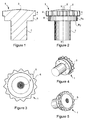
- The
Figures 1 to 3 are views respectively in axial section, in side view and in plan view of a screw head used with a screwdriver according to the invention; - The
Figures 4 and 5 are perspective views of the illustrated screw on theFigures 1 to 3 ; - The
figure 6 is a perspective view of a screw bit according to the invention, in the screwing position; - The
figure 7 is an axial section of the screwed end representedfigure 6 ; - The
figure 8 is a front view of the socket; - The
figure 9 is a partial half-section view on a larger scale of the tip shownFigures 6 and 7 ; - The
figure 10 is a partial half-section similar to that of thefigure 9 but in the open position of the jaws; - The
figure 11 is an elevational view of the rod / bottom / core assembly of the tip shownFigures 6 to 9 ; - The
Figures 12 and 13 show the axially movable tubular section of the sleeve in perspective (figure 12 ) and in axial section (figure 13 ); - The
figure 14 is a perspective view of a bit; - The
figure 15 is an axial section of an alternative embodiment of the nozzle according to the invention.
Dans l'exemple représenté sur les
Cette tête de vis 1 présente une face supérieure bombée 2 avec au centre une cuvette d'injection 3. La présence de cette cuvette n'existe que dans le cas où la tête est surmoulée. Par contre, dans le cas d'un forgeage à froid (roulage), la face supérieure de la tête sera continûment bombée. Le bord périphérique 4 de la tête 1 est dentelé et comprend ici quinze dents 5 séparées par des échancrures 6 formant un angle d'environ 120°.This
Cette tête 1 est reliée à une tige coaxiale 7 par l'intermédiaire d'une portion cylindrique sous-tête 8 dont le diamètre est sensiblement égal à la distance entre le fond des échancrures et l'axe X, X' de la vis. Dans cet exemple, la hauteur de la portion cylindrique 8 est sensiblement égale à la hauteur du bord périphérique 4 de la tête 1. Le diamètre de la tige 7 de la vis, au niveau de son raccordement à la portion cylindrique 8, est très inférieur à celui de la tête 1 (environ 50 %), le raccord entre la portion cylindrique 8 avec le bord périphérique 4 de la tête 1 et avec l'extrémité de la tige 7, s'effectuant grâce à des épaulements radiaux R1, R2.This
Bien entendu, cette vis pourra être vissée à l'aide d'un outil à main présentant un embout tubulaire dont le profil intérieur correspond à la forme extérieure dentelée de la tête 1.Of course, this screw can be screwed using a hand tool having a tubular nozzle whose inner profile corresponds to the outer serrated form of the
Néanmoins, elle convient tout particulièrement à l'embout de vissage illustré sur les
Le fond 11 présente une forme circulaire et comporte, à sa périphérie, trois crabots 13 à 120° l'un de l'autre qui s'étendent radialement en saillie.The
Le diamètre extérieur du fond 11 est sensiblement égal au diamètre intérieur de la douille 10.The outside diameter of the
La douille 10 comporte trois gorges axiales G1 à G3 à 120° l'une de l'autre dans lesquelles s'engagent respectivement les crabots 13.The
La fixation en position de la douille 10 et du fond 11 est assurée au moyen d'une goupille 14 qui s'engage dans un perçage radial passant au travers dudit fond 11 et de ladite douille 10.The fixing in position of the
La douille 10 présente, du côté opposé au fond, une cavité coaxiale dans laquelle s'étend un noyau cylindrique coaxial 15 qui délimite, dans cette cavité coaxiale, deux chambres successives, à savoir :
- une première chambre 16 destinée notamment à recevoir la tête 1 de la vis, cette chambre 16 présentant une section à profil dentelé (denture 17) sensiblement complémentaire à celui de la tête 1 de la vis,
- une chambre annulaire 18 dans laquelle sont disposés des mors axialement mobiles M1 - M3 munis d'éléments de préhension (mâchoires) qui s'engagent dans la chambre 16.
- a
first chamber 16 intended in particular to receive thehead 1 of the screw, thischamber 16 having a serrated profile section (toothing 17) substantially complementary to that of thehead 1 of the screw, - an
annular chamber 18 in which are disposed axially movable jaws M 1 - M 3 provided with gripping elements (jaws) which engage in thechamber 16.
Ces mors M1 - M3 sont montés basculants et sont retenus axialement sur un manchon tubulaire 19 grâce à des moyens d'articulation. Ils comprennent :
- d'une part, une face inférieure comprenant dans sa partie antérieure une encoche 20 dans laquelle la bordure périphérique de la vis 1 peut venir s'engager et, à une distance prédéterminée de leur extrémité postérieure, une encoche circulaire 21 constituant une première partie des moyens d'articulation et,
- d'autre part, une face supérieure dont la partie antérieure 22 est oblique et constitue un profil de came et une partie postérieure comprenant une encoche 23 par laquelle s'engage un jonc annulaire élastique 24 coaxial à l'embout.
- on the one hand, a lower face comprising in its front part a
notch 20 in which the peripheral edge of thescrew 1 can engage and, at a predetermined distance from their posterior end, acircular notch 21 constituting a first part of the articulation means and, - on the other hand, an upper face whose
anterior portion 22 is oblique and constitutes a cam profile and a rear portion comprising anotch 23 through which engages an annularresilient ring 24 coaxial with the tip.
Dans ces exemples, le noyau 15 présente une forme cylindrique et est muni d'un alésage taraudé coaxial dans lequel vient se visser une vis 26 dont la tête, cylindrique, 27, présente un diamètre supérieur à celui de la forme cylindrique du noyau 15.In these examples, the
Le manchon tubulaire 19 comprend, quant à lui, une surface intérieure présentant une forme cylindrique étagée dont une première partie 28 (postérieure) présente un diamètre sensiblement égal à celui de la forme cylindrique du noyau 15 tandis qu'une deuxième partie 29 (antérieure) présente un diamètre sensiblement égal au diamètre de la tête de la vis 26.The
Comme illustré
Grâce à ces dispositions, les mors M1 à M3 s'engagent sur le manchon tubulaire, à 120° les uns des autres, dans une position selon laquelle leurs parties postérieures s'engagent dans une échancrure respective 36 tandis que l'excroissance annulaire du manchon 33 s'engage dans leurs encoches 21 (
Compte tenu de cette structure, le manchon tubulaire 19 peut se déplacer entre :
- une position fin de course avant dans laquelle les mors M1 à M3 s'étendent au-delà de l'ouverture de la douille tubulaire 10, dans une position ouverte due à l'action du jonc annulaire élastique 24 et au profil de came de la
face extérieure 22 des mors, et - une position fin de course arrière dans laquelle les mors M1 à M3 sont sensiblement rentrés à l'intérieur de la douille 10 et se trouvent resserrés les uns vers les autres en raison de l'action de la douille 10 sur le profil de came 22 contre l'action engendrée par le jonc élastique 24.
- a forward end position in which the jaws M 1 to M 3 extend beyond the opening of the
tubular sleeve 10, in an open position due to the action of the elasticannular ring 24 and the cam profile theouter face 22 of the jaws, and - a rear end position in which the jaws M 1 to M 3 are substantially retracted inside the
sleeve 10 and are tightened the to each other because of the action of thesleeve 10 on thecam profile 22 against the action generated by theelastic ring 24.
Comme précédemment mentionné, la face intérieure de la douille 10 comprend, au voisinage du fond, une gorge annulaire G dans laquelle vient s'engager le jonc 24 lorsque le manchon tubulaire 19 se trouve en position fin de course arrière.As previously mentioned, the inner face of the
Grâce à ces dispositions, en position déployée, les extrémités des mors M1 à M3 ressortent de la douille 10 et sont orientées radialement vers l'extérieur de manière à ce que les encoches 20 soient suffisamment espacées les unes des autres pour recevoir la tête 1 de la vis. Le collet 30 situé à l'extrémité antérieure du manchon tubulaire 19 se trouve alors en avant de la tête 1 de la vis V.Thanks to these provisions, in the deployed position, the ends of the jaws M 1 to M 3 emerge from the
Ainsi, lors de l'introduction de la tête 1 de la vis V à l'intérieur de la cavité de la douille 10, les mors M1 à M3 étant en position ouverte, la face antérieure de la tête 1 vient porter sur le collet 30 et repousser vers l'arrière l'ensemble mobile comprenant le manchon tubulaire 19, les mors M1 à M3 et le jonc 24. Au cours de ce déplacement, les mors M1 à M3 se referment en raison de l'action de la bordure antérieure de la douille 10 sur les parties obliques 22 de la face supérieure desdits mors M1 à M3 en emprisonnant la tête 1 de la vis V.Thus, during the introduction of the
En fin de course, les extrémités arrière du manchon tubulaire 19 et des mors M1 à M3 viennent en butée contre le fond 11. Dans cette position, l'arête supérieure située à l'extrémité antérieure des mors M1 à M3 se trouve engagée en appui sur la face intérieure de la cavité de la douille 10 tandis que les extrémités inférieures des mors M1 à M3 viennent porter sur la partie cylindrique sous-tête 8 de la vis V. Le jonc 24 se trouve alors partiellement engagé dans la gorge G et assure un blocage axial temporaire de l'ensemble mobile dans la cavité du manchon tubulaire 10.At the end of the stroke, the rear ends of the
Dans cette position, un effort transversal appliqué sur la tige de la vis se trouve repris par la douille 10 par l'intermédiaire des extrémités des mors M1 à M3 tandis que ces derniers se trouvent axialement retenus sur le manchon tubulaire 19 grâce à l'engagement de la protubérance annulaire 33 dans l'encoche 21.In this position, a transverse force applied to the rod of the screw is taken up by the
Par ailleurs, compte tenu du fait que l'ensemble mobile se trouve en butée contre le fond 11, seul un déplacement vers l'avant est possible à condition toutefois que l'effort de traction exercé dépasse un seuil prédéterminé pour lequel le jonc élastique 24, en se comprimant, échappe à la gorge G.Moreover, taking into account the fact that the moving assembly is in abutment against the bottom 11, only a forward movement is possible provided however that the tensile force exerted exceeds a predetermined threshold for which the
Dans ce cas, la traction exercée par la vis provoque un déplacement de l'ensemble mobile vers l'avant avec ouverture simultanée des mors M1 à M3 sous l'effet de l'action du jonc élastique 24. En fin de course avant de l'ensemble mobile, la tête 1 de la vis peut être dégagée des mors M1 à M3.In this case, the traction exerted by the screw causes the moving assembly to move forward with simultaneous opening of the jaws M 1 to M 3 under the effect of the action of the
Bien entendu, lorsque la tête 1 de la vis se trouve emprisonnée à l'intérieur de la douille 10, le profil dentelé de la douille 10 est en prise avec celui de la tête 1 de manière à pouvoir lui transmettre un couple de vissage. L'entraînement en rotation de la vis est directement assuré par la douille 10. De ce fait, on utilise de façon optimale la forme tubulaire de cette douille pour assurer la transmission du couple de vissage.Of course, when the
Un autre avantage de cette solution consiste en ce que, lors du vissage de la vis, les efforts axiaux engendrés sur la tige 12, en direction de la vis, sont directement répercutés sur la tête de cette vis. Ainsi, cet embout est utilisable notamment pour le vissage de vis autoperforantes à percussion dans un matériau tel que, par exemple, du béton cellulaire.Another advantage of this solution is that, during the screwing of the screw, the axial forces generated on the
L'embout peut être facilement adapté pour le vissage d'une vis 35 dont la tête 36 présente, à sa périphérie, un bord circulaire et, dans sa partie centrale, une empreinte 37 (par exemple cruciforme) permettant son entraînement en rotation.The tip can be easily adapted for screwing a
Dans ce cas, la vis 38 prévue à l'extrémité du noyau pourra comprendre une tête présentant une forme complémentaire à celle de l'empreinte convexe 37 de la vis 35 ; la douille 10 présentera un profil lisse à la place du profil dentelé et l'encoche des mors M1 à M3 présentera une portion conique apte à venir en prise avec la face conique sous-tête de la vis 35 (
Claims (10)
- End fitting for gripping and screwing a screw (1) comprising a bushing (10) having, at one of the ends thereof, a coaxial cavity and a fixed coaxial core (15) with respect to the bushing (10) which extends coaxially to said cavity delimiting, therewith, a substantially cylindrical front volume (16) inside which the head of the screw (1) may be introduced and an annular volume (18) wherein axially mobile jaws (M1 to M3) equipped with gripping members which are engaged in the front volume (16) of the bushing (10) are mounted,
characterised in that the jaws (M1 to M3) are mounted tilting and retained axially on a tubular sleeve (19) by means of articulation means (33), said tubular sleeve (19) being axially mobile on the core (15) so as to be able to change from a front limit position wherein the jaws (M1 to M3) are in the deployed state under the effect of resilient means (24) to a rear limit position wherein the jaws (M1 to M3) are moved to and held in a closed position by means of the cooperation of a conformation of the jaws (M1 to M3) with a suitable conformation of the bushing (10) or the core (15) which causes the tilting of the jaws (M1 to M3) about the articulation means (33), the return to the front limit position of the sleeve (19) subsequently causing the jaws to change to the open position. - End fitting according to claim 1, characterised in that the jaws (M1 to M3) consist of rods having, in the front part thereof, a notch (20) wherein the peripheral edge of the head of the screw (1) may be engaged in the closed position and, in the vicinity of the rear end thereof, an outer face equipped with a groove (23) wherein a resilient ring (24) is engaged.
- End fitting according to any of claims 1 and 2, characterised in that the outer face of the jaws (M1 to M3) comprises in the front part thereof, an oblique portion (22) with respect to the longitudinal axis of the end fitting, said oblique portion (22) forming a ramp cooperating with the front edge of the orifice of the bushing (10) to cause the tilting of the jaws (M1 to M3) in the closed position.
- End fitting according to any of the above claims, characterised in that the bushing (10) comprises in the base of the cavity, an annular bell mouth (G) wherein the ring (24) may partially be engaged after resilient deformation to lock the mobile assembly consisting of the tubular sleeve (19) and the jaws (M1 to M3) in the rear limit position, the jaws (M1 to M3) being in this case in the closed position, unlocking only being obtained by applying on the jaws (M1 to M3) an axial traction of a sufficient amplitude so that the ring (24), being deformed resiliently, can escape the bell mouth (G).
- End fitting according to any of the above claims, characterised in that the core (15) has a staged cylindrical shape comprising a cylindrical portion (31) whereon the tubular sleeve (19) slides, said cylindrical portion (31) being limited, on one side, by a shoulder forming the base (11) of the cavity and, on the other, by a cylindrical portion of greater diameter (27).
- End fitting according to claim 5, characterised in that the portion of greater diameter (27) consists of the head of a screw (26) screwed into a threaded axial holes produced in the core (15).
- End fitting according to any of the above claims, characterised in that the inner surface of the bushing (10) comprises conformations (17) capable of engaging with the corresponding conformations of the head of the screw (1) to be screwed.
- End fitting according to any of the above claims, characterised in that the inner surface of the bushing (10) comprises axial grooves used to guide the jaws (M1 to M3).
- End fitting according to claim 8, characterised in that the bushing (10) is closed on one side by a base (11) attached to a coaxial rod (12) intended to be engaged in the chuck of a screw driving machine, said base comprising jaw couplings which are engaged in said grooves.
- End fitting according to claim 5, characterised in that the portion of greater diameter of the core (15) is conformed so as to engage with a recess (37) formed on the screw head (35).
Applications Claiming Priority (1)
| Application Number | Priority Date | Filing Date | Title |
|---|---|---|---|
| PCT/FR2004/000566 WO2005097410A1 (en) | 2004-03-10 | 2004-03-10 | Grasping clamping end for a screwing device |
Publications (2)
| Publication Number | Publication Date |
|---|---|
| EP1722929A1 EP1722929A1 (en) | 2006-11-22 |
| EP1722929B1 true EP1722929B1 (en) | 2009-04-29 |
Family
ID=34957646
Family Applications (1)
| Application Number | Title | Priority Date | Filing Date |
|---|---|---|---|
| EP04718985A Expired - Lifetime EP1722929B1 (en) | 2004-03-10 | 2004-03-10 | Grasping clamping end for a screwing device |
Country Status (6)
| Country | Link |
|---|---|
| EP (1) | EP1722929B1 (en) |
| AT (1) | ATE429998T1 (en) |
| DE (1) | DE602004020929D1 (en) |
| ES (1) | ES2325262T3 (en) |
| PT (1) | PT1722929E (en) |
| WO (1) | WO2005097410A1 (en) |
Families Citing this family (1)
| Publication number | Priority date | Publication date | Assignee | Title |
|---|---|---|---|---|
| DE202014103714U1 (en) | 2014-08-11 | 2015-11-12 | Wera-Werk Hermann Werner Gmbh & Co. Kg | On a peripheral surface of a screw head torque transmitting attacking screw |
Family Cites Families (5)
| Publication number | Priority date | Publication date | Assignee | Title |
|---|---|---|---|---|
| US3379231A (en) * | 1966-11-29 | 1968-04-23 | John Gallo Sr. | Fastener holder and driver |
| US3758938A (en) * | 1971-11-03 | 1973-09-18 | Cooper Ind Inc | Tool for applying and locking threaded fasteners and method |
| DE19650799C1 (en) * | 1996-12-06 | 1998-07-02 | Sfs Ind Holding Ag | Nut for receiving or inserting into a fastener head (es) |
| DE19712783C2 (en) * | 1997-03-26 | 2000-11-09 | Sfs Ind Holding Ag Heerbrugg | Screwdriver element |
| FR2842447B1 (en) * | 2002-07-19 | 2005-02-25 | Etanco L R | PRETENSION AND SCREW BIT FOR SPECIAL HEAD SCREWS. |
-
2004
- 2004-03-10 EP EP04718985A patent/EP1722929B1/en not_active Expired - Lifetime
- 2004-03-10 AT AT04718985T patent/ATE429998T1/en not_active IP Right Cessation
- 2004-03-10 PT PT04718985T patent/PT1722929E/en unknown
- 2004-03-10 WO PCT/FR2004/000566 patent/WO2005097410A1/en not_active Application Discontinuation
- 2004-03-10 DE DE602004020929T patent/DE602004020929D1/en not_active Expired - Lifetime
- 2004-03-10 ES ES04718985T patent/ES2325262T3/en not_active Expired - Lifetime
Also Published As
| Publication number | Publication date |
|---|---|
| ATE429998T1 (en) | 2009-05-15 |
| ES2325262T3 (en) | 2009-08-31 |
| WO2005097410A1 (en) | 2005-10-20 |
| DE602004020929D1 (en) | 2009-06-10 |
| EP1722929A1 (en) | 2006-11-22 |
| PT1722929E (en) | 2009-06-26 |
Similar Documents
| Publication | Publication Date | Title |
|---|---|---|
| EP3539685B1 (en) | Tool and method for installing a blind fastener | |
| EP1419837B1 (en) | Tool holder with locking system | |
| FR2761127A1 (en) | Insert for fixing articles on surfaces, e.g. blind holes, on motor vehicles, in vehicle assembly lines | |
| EP2389264B1 (en) | Tool holder mandrel for equipping a rotating machine | |
| EP1118401B1 (en) | Expanding device for forming bells at tube ends | |
| FR2540772A1 (en) | AUTOMATIC TOOL FOR STUDDING | |
| FR2465569A1 (en) | ROUND TUBULAR HANDLE FOR DOMESTIC TOOLS | |
| EP1553310B1 (en) | A reversible device for locking an end piece on a structure with adjustable position | |
| EP0706442A1 (en) | Tightening tool such as a screwdriver | |
| EP1722929B1 (en) | Grasping clamping end for a screwing device | |
| EP2265411B1 (en) | Gripping and screwing bit intended to equip a screwing device | |
| FR2975323A1 (en) | Device for extracting self lubricating ring fixed in bore of landing gear box of aircraft, has expandable member comprising bits, where each of bits has transom forming axial stop for side face of ring when member is in deployed position | |
| EP1382418A1 (en) | Schraubvorrichtung bestehend aus einer Schraube mit Spezialkopf und einem für diesen Kopf geeigneten Steckschlüssel | |
| EP1382863B1 (en) | Screw with a head specially adapted to a tool bit for holding and screwing it | |
| EP0618045A1 (en) | Strap wrench, especially for vehicle oil filters | |
| CA2075962C (en) | Method of riveting materials using a blind rivet, and corresponding blind rivets | |
| FR2843062A1 (en) | Gripper sleeve for fastener driver has shaft with movable jaw mounted in end bore and O-ring to retain jaw | |
| WO2017216504A1 (en) | Quick-release setting tool for an element to be crimped | |
| FR2785341A1 (en) | Releasable shaft lock for drive transmission has recessed key fitting in hole in component to be mounted on shaft to releasable lock them together | |
| WO2000047904A1 (en) | Device for connecting profiled sections | |
| FR3039448A1 (en) | MAGNETIC SCREW SLEEVE. | |
| FR2883210A1 (en) | Mandrel for holding tool, e.g. drill bit, for turning machine, includes central piece having holding jaws and rear operating collar with blocked relative rotation and axial translation | |
| WO2006030083A1 (en) | Device for setting and screwing an element for fixing a thermal insulation coating on a support structure | |
| FR3039784A1 (en) | BUSHING BUSH WITH BALLS. | |
| FR2946383A1 (en) | Adjustable stopper for use in motor vehicle, has blocking member provided in retainer in locked position, where retainer includes external tube and inner rod, and bush section surrounds rod and surrounded by tubular section |
Legal Events
| Date | Code | Title | Description |
|---|---|---|---|
| PUAI | Public reference made under article 153(3) epc to a published international application that has entered the european phase |
Free format text: ORIGINAL CODE: 0009012 |
|
| 17P | Request for examination filed |
Effective date: 20060829 |
|
| AK | Designated contracting states |
Kind code of ref document: A1 Designated state(s): AT BE BG CH CY CZ DE DK EE ES FI FR GB GR HU IE IT LI LU MC NL PL PT RO SE SI SK TR |
|
| DAX | Request for extension of the european patent (deleted) | ||
| GRAP | Despatch of communication of intention to grant a patent |
Free format text: ORIGINAL CODE: EPIDOSNIGR1 |
|
| GRAP | Despatch of communication of intention to grant a patent |
Free format text: ORIGINAL CODE: EPIDOSNIGR1 |
|
| RAP1 | Party data changed (applicant data changed or rights of an application transferred) |
Owner name: LR ETANCO |
|
| GRAS | Grant fee paid |
Free format text: ORIGINAL CODE: EPIDOSNIGR3 |
|
| GRAA | (expected) grant |
Free format text: ORIGINAL CODE: 0009210 |
|
| RAP1 | Party data changed (applicant data changed or rights of an application transferred) |
Owner name: ATELIERS LR ETANCO |
|
| AK | Designated contracting states |
Kind code of ref document: B1 Designated state(s): AT BE BG CH CY CZ DE DK EE ES FI FR GB GR HU IE IT LI LU MC NL PL PT RO SE SI SK TR |
|
| REG | Reference to a national code |
Ref country code: GB Ref legal event code: FG4D Free format text: NOT ENGLISH |
|
| REG | Reference to a national code |
Ref country code: CH Ref legal event code: EP |
|
| REG | Reference to a national code |
Ref country code: RO Ref legal event code: EPE |
|
| REF | Corresponds to: |
Ref document number: 602004020929 Country of ref document: DE Date of ref document: 20090610 Kind code of ref document: P |
|
| REG | Reference to a national code |
Ref country code: IE Ref legal event code: FG4D |
|
| REG | Reference to a national code |
Ref country code: PT Ref legal event code: SC4A Free format text: AVAILABILITY OF NATIONAL TRANSLATION Effective date: 20090619 |
|
| REG | Reference to a national code |
Ref country code: CH Ref legal event code: NV Representative=s name: CABINET MOUTARD |
|
| REG | Reference to a national code |
Ref country code: ES Ref legal event code: FG2A Ref document number: 2325262 Country of ref document: ES Kind code of ref document: T3 |
|
| PG25 | Lapsed in a contracting state [announced via postgrant information from national office to epo] |
Ref country code: FI Free format text: LAPSE BECAUSE OF FAILURE TO SUBMIT A TRANSLATION OF THE DESCRIPTION OR TO PAY THE FEE WITHIN THE PRESCRIBED TIME-LIMIT Effective date: 20090429 Ref country code: AT Free format text: LAPSE BECAUSE OF FAILURE TO SUBMIT A TRANSLATION OF THE DESCRIPTION OR TO PAY THE FEE WITHIN THE PRESCRIBED TIME-LIMIT Effective date: 20090429 |
|
| PG25 | Lapsed in a contracting state [announced via postgrant information from national office to epo] |
Ref country code: SE Free format text: LAPSE BECAUSE OF FAILURE TO SUBMIT A TRANSLATION OF THE DESCRIPTION OR TO PAY THE FEE WITHIN THE PRESCRIBED TIME-LIMIT Effective date: 20090729 Ref country code: SI Free format text: LAPSE BECAUSE OF FAILURE TO SUBMIT A TRANSLATION OF THE DESCRIPTION OR TO PAY THE FEE WITHIN THE PRESCRIBED TIME-LIMIT Effective date: 20090429 Ref country code: PL Free format text: LAPSE BECAUSE OF FAILURE TO SUBMIT A TRANSLATION OF THE DESCRIPTION OR TO PAY THE FEE WITHIN THE PRESCRIBED TIME-LIMIT Effective date: 20090429 |
|
| REG | Reference to a national code |
Ref country code: IE Ref legal event code: FD4D |
|
| PG25 | Lapsed in a contracting state [announced via postgrant information from national office to epo] |
Ref country code: DK Free format text: LAPSE BECAUSE OF FAILURE TO SUBMIT A TRANSLATION OF THE DESCRIPTION OR TO PAY THE FEE WITHIN THE PRESCRIBED TIME-LIMIT Effective date: 20090429 Ref country code: EE Free format text: LAPSE BECAUSE OF FAILURE TO SUBMIT A TRANSLATION OF THE DESCRIPTION OR TO PAY THE FEE WITHIN THE PRESCRIBED TIME-LIMIT Effective date: 20090429 Ref country code: IE Free format text: LAPSE BECAUSE OF FAILURE TO SUBMIT A TRANSLATION OF THE DESCRIPTION OR TO PAY THE FEE WITHIN THE PRESCRIBED TIME-LIMIT Effective date: 20090429 |
|
| PLBE | No opposition filed within time limit |
Free format text: ORIGINAL CODE: 0009261 |
|
| STAA | Information on the status of an ep patent application or granted ep patent |
Free format text: STATUS: NO OPPOSITION FILED WITHIN TIME LIMIT |
|
| PG25 | Lapsed in a contracting state [announced via postgrant information from national office to epo] |
Ref country code: BG Free format text: LAPSE BECAUSE OF FAILURE TO SUBMIT A TRANSLATION OF THE DESCRIPTION OR TO PAY THE FEE WITHIN THE PRESCRIBED TIME-LIMIT Effective date: 20090729 |
|
| 26N | No opposition filed |
Effective date: 20100201 |
|
| PG25 | Lapsed in a contracting state [announced via postgrant information from national office to epo] |
Ref country code: GR Free format text: LAPSE BECAUSE OF FAILURE TO SUBMIT A TRANSLATION OF THE DESCRIPTION OR TO PAY THE FEE WITHIN THE PRESCRIBED TIME-LIMIT Effective date: 20090730 Ref country code: MC Free format text: LAPSE BECAUSE OF NON-PAYMENT OF DUE FEES Effective date: 20100331 |
|
| GBPC | Gb: european patent ceased through non-payment of renewal fee |
Effective date: 20100310 |
|
| PG25 | Lapsed in a contracting state [announced via postgrant information from national office to epo] |
Ref country code: GB Free format text: LAPSE BECAUSE OF NON-PAYMENT OF DUE FEES Effective date: 20100310 |
|
| REG | Reference to a national code |
Ref country code: CH Ref legal event code: PFA Owner name: ATELIERS LR ETANCO Free format text: ATELIERS LR ETANCO#PARC LES ERABLES - BATIMENT 1 66 ROUTE DE SARTROUVILLE#78230 LE PECQ (FR) -TRANSFER TO- ATELIERS LR ETANCO#PARC LES ERABLES - BATIMENT 1 66 ROUTE DE SARTROUVILLE#78230 LE PECQ (FR) |
|
| PG25 | Lapsed in a contracting state [announced via postgrant information from national office to epo] |
Ref country code: CY Free format text: LAPSE BECAUSE OF FAILURE TO SUBMIT A TRANSLATION OF THE DESCRIPTION OR TO PAY THE FEE WITHIN THE PRESCRIBED TIME-LIMIT Effective date: 20090429 |
|
| PG25 | Lapsed in a contracting state [announced via postgrant information from national office to epo] |
Ref country code: HU Free format text: LAPSE BECAUSE OF FAILURE TO SUBMIT A TRANSLATION OF THE DESCRIPTION OR TO PAY THE FEE WITHIN THE PRESCRIBED TIME-LIMIT Effective date: 20091030 |
|
| PG25 | Lapsed in a contracting state [announced via postgrant information from national office to epo] |
Ref country code: TR Free format text: LAPSE BECAUSE OF FAILURE TO SUBMIT A TRANSLATION OF THE DESCRIPTION OR TO PAY THE FEE WITHIN THE PRESCRIBED TIME-LIMIT Effective date: 20090429 |
|
| REG | Reference to a national code |
Ref country code: CH Ref legal event code: PCAR Free format text: NEW ADDRESS: RUE DE LYON 75 - 4EME ETAGE, 1203 GENEVE (CH) |
|
| REG | Reference to a national code |
Ref country code: FR Ref legal event code: PLFP Year of fee payment: 13 |
|
| REG | Reference to a national code |
Ref country code: CH Ref legal event code: PCAR Free format text: NEW ADDRESS: BOULEVARD GEORGES-FAVON 3 (1ER ETAGE), 1204 GENEVE (CH) |
|
| REG | Reference to a national code |
Ref country code: FR Ref legal event code: PLFP Year of fee payment: 14 |
|
| REG | Reference to a national code |
Ref country code: FR Ref legal event code: PLFP Year of fee payment: 15 |
|
| PGFP | Annual fee paid to national office [announced via postgrant information from national office to epo] |
Ref country code: RO Payment date: 20230301 Year of fee payment: 20 Ref country code: LU Payment date: 20230330 Year of fee payment: 20 Ref country code: FR Payment date: 20230330 Year of fee payment: 20 Ref country code: CZ Payment date: 20230301 Year of fee payment: 20 |
|
| PGFP | Annual fee paid to national office [announced via postgrant information from national office to epo] |
Ref country code: SK Payment date: 20230228 Year of fee payment: 20 Ref country code: PT Payment date: 20230306 Year of fee payment: 20 Ref country code: IT Payment date: 20230330 Year of fee payment: 20 Ref country code: DE Payment date: 20230330 Year of fee payment: 20 Ref country code: BE Payment date: 20230330 Year of fee payment: 20 |
|
| PGFP | Annual fee paid to national office [announced via postgrant information from national office to epo] |
Ref country code: NL Payment date: 20230330 Year of fee payment: 20 |
|
| P01 | Opt-out of the competence of the unified patent court (upc) registered |
Effective date: 20230526 |
|
| PGFP | Annual fee paid to national office [announced via postgrant information from national office to epo] |
Ref country code: ES Payment date: 20230504 Year of fee payment: 20 Ref country code: CH Payment date: 20230404 Year of fee payment: 20 |
|
| REG | Reference to a national code |
Ref country code: DE Ref legal event code: R071 Ref document number: 602004020929 Country of ref document: DE |
|
| REG | Reference to a national code |
Ref country code: NL Ref legal event code: MK Effective date: 20240309 |
|
| REG | Reference to a national code |
Ref country code: CH Ref legal event code: PL |
|
| REG | Reference to a national code |
Ref country code: SK Ref legal event code: MK4A Ref document number: E 5739 Country of ref document: SK Expiry date: 20240310 Ref country code: ES Ref legal event code: FD2A Effective date: 20240327 |
|
| PG25 | Lapsed in a contracting state [announced via postgrant information from national office to epo] |
Ref country code: ES Free format text: LAPSE BECAUSE OF EXPIRATION OF PROTECTION Effective date: 20240311 |