EP2265411B1 - Gripping and screwing bit intended to equip a screwing device - Google Patents
Gripping and screwing bit intended to equip a screwing device Download PDFInfo
- Publication number
- EP2265411B1 EP2265411B1 EP09728518A EP09728518A EP2265411B1 EP 2265411 B1 EP2265411 B1 EP 2265411B1 EP 09728518 A EP09728518 A EP 09728518A EP 09728518 A EP09728518 A EP 09728518A EP 2265411 B1 EP2265411 B1 EP 2265411B1
- Authority
- EP
- European Patent Office
- Prior art keywords
- jaws
- head
- screw
- sleeve
- bit according
- Prior art date
- Legal status (The legal status is an assumption and is not a legal conclusion. Google has not performed a legal analysis and makes no representation as to the accuracy of the status listed.)
- Active
Links
Images

Classifications
-
- B—PERFORMING OPERATIONS; TRANSPORTING
- B25—HAND TOOLS; PORTABLE POWER-DRIVEN TOOLS; MANIPULATORS
- B25B—TOOLS OR BENCH DEVICES NOT OTHERWISE PROVIDED FOR, FOR FASTENING, CONNECTING, DISENGAGING OR HOLDING
- B25B13/00—Spanners; Wrenches
- B25B13/44—Spanners; Wrenches of the chuck type
-
- B—PERFORMING OPERATIONS; TRANSPORTING
- B25—HAND TOOLS; PORTABLE POWER-DRIVEN TOOLS; MANIPULATORS
- B25B—TOOLS OR BENCH DEVICES NOT OTHERWISE PROVIDED FOR, FOR FASTENING, CONNECTING, DISENGAGING OR HOLDING
- B25B23/00—Details of, or accessories for, spanners, wrenches, screwdrivers
- B25B23/02—Arrangements for handling screws or nuts
- B25B23/08—Arrangements for handling screws or nuts for holding or positioning screw or nut prior to or during its rotation
- B25B23/10—Arrangements for handling screws or nuts for holding or positioning screw or nut prior to or during its rotation using mechanical gripping means
Definitions
- This head 1 is connected to a coaxial rod 7 via a cylindrical portion under head 8 whose diameter is substantially equal to the distance between the bottom of the notches and the axis XX 'of the screw.
- This screw can be screwed using a hand tool having a tubular nozzle whose inner profile corresponds to the outer serrated shape of the head 1.
Abstract
Description
La présente invention concerne un embout de préhension et de vissage destiné à équiper un appareil de vissage tel que, par exemple, une visseuse/dévisseuse motorisée.The present invention relates to a gripping and screwing end for fitting a screwing device such as, for example, a motorized screwdriver / unscrewer.
Elle s'applique notamment, à des vis dont la tête présente à sa périphérie des conformations destinées à coopérer avec un outil de vissage, d'une part, pour assurer une solidarisation axiale entre l'outil et la vis et, d'autre part, pour permettre à l'outil d'exercer sur la vis un couple de vissage. Un embout tel que définit dans le préambule de la revendication 1 est connu de l'art antérieur, par example par le document
Par le brevet
Cette solution présente l'avantage de dissocier la fonction d'entraînement en rotation de la fonction de préhension. De ce fait, les moyens de préhension qui n'ont plus de fonction d'entraînement en rotation, peuvent présenter des dimensions réduites. L'efficacité du vissage demeure garantie du fait que la douille de vissage se comporte comme une clé à douille classique de section indéformable.This solution has the advantage of separating the rotational drive function from the gripping function. As a result, the gripping means, which no longer have a rotational drive function, may have reduced dimensions. The effectiveness of the screwing remains guaranteed by the fact that the screwing bush behaves like a conventional socket wrench of indeformable section.
Néanmoins, cette solution présente un inconvénient dû au fait que, compte tenu de l'indéformabilité de la douille, elle ne convient bien que pour des vis dont les têtes présentent une précision relativement élevée.However, this solution has a drawback due to the fact that, given the indeformability of the sleeve, it is only suitable for screws whose heads have a relatively high accuracy.
Si la section extérieure de la tête ne correspond pas exactement à la section intérieure de la douille, on observe :
- soit une impossibilité d'engager la tête dans la douille,
- soit un jeu entre la tête et la douille, ce jeu s'avérant nuisible du fait qu'il conduit à un effet de rotule de la tête à l'intérieur de la douille.
- either an impossibility to engage the head in the socket,
- or a game between the head and the socket, this game proving harmful because it leads to a head effect of the ball inside the socket.
Il est clair qu'un renforcement des moyens de préhension pour réduire cet effet de rotule irait à l'encontre du but recherché dans cette solution, qui vise au contraire à profiter de la séparation des fonctions de préhension et d'entraînement pour diminuer les dimensions des moyens de préhension.It is clear that a reinforcement of the gripping means to reduce this kneecap effect would be counter to the purpose sought in this solution, which aims on the contrary to take advantage of the separation of the gripping and driving functions to reduce the dimensions gripping means.
Or, il s'avère que les techniques de production à cadence élevée ne permettent pas toujours de garantir une précision suffisante des têtes de vis pour éviter les inconvénients précédemment évoqués. Ceci est plus particulièrement le cas lorsqu'en fin du cycle de fabrication, les têtes de vis subissent un traitement de surface se traduisant par un dépôt de matière d'épaisseur mal contrôlée (dépôt de métal, d'oxyde métallique, de peinture, etc...).However, it turns out that high-speed production techniques do not always make it possible to guarantee sufficient precision of the screw heads to avoid the disadvantages mentioned above. This is particularly the case when, at the end of the manufacturing cycle, the screw heads undergo a surface treatment resulting in a deposit of material of poorly controlled thickness (deposition of metal, metal oxide, paint, etc. ...).
En outre, la solution précédemment décrite prévoit une coopération d'une conformation des mors avec une conformation appropriée de la douille pour provoquer un basculement des mors autour de moyens d'articulation, lorsque les mors passent d'une position fin de course avant où ils sont ouverts, à une position fin de course arrière dans laquelle les mors sont rentrés dans la douille en position fermée. En fait, ces conformations font intervenir des rampes qui s'étendent obliquement par rapport à l'axe longitudinal de la douille.In addition, the previously described solution provides a cooperation of a conformation of the jaws with an appropriate conformation of the sleeve to cause a tilting of the jaws around articulation means, when the jaws move from a forward end position where they are open to a rear end position in which the jaws are retracted into the socket in the closed position. In fact, these conformations involve ramps that extend obliquely with respect to the longitudinal axis of the bushing.
La présence de ces rampes et le basculement des mors impliquent la présence d'un espace annulaire important entre la douille et les mors et donc un accroissement du diamètre de la douille.The presence of these ramps and tilting of the jaws imply the presence of a large annular space between the sleeve and the jaws and therefore an increase in the diameter of the sleeve.
Cette augmentation de volume se trouve amplifiée du fait de la présence, à l'intérieur de la douille, d'un noyau central coaxial permettant d'assurer le coulissement axial des mors (la présence des rampes empêche que ce coulissement puisse être assuré par la surface extérieure de la douille).This increase in volume is amplified because of the presence, inside the sleeve, of a coaxial central core for ensuring the axial sliding of the jaws (the presence of the ramps prevents this sliding can be ensured by the outer surface of the socket).
L'invention a donc plus particulièrement pour but de supprimer ces inconvénients.The object of the invention is therefore more particularly to eliminate these disadvantages.
A cet effet, elle propose un embout de préhension et de vissage comportant les caractéristiques de la revendication 1,For this purpose, it proposes a gripping and screwing tip comprising the features of
Avantageusement, les deux mors pourront présenter un corps allongé terminé, d'un côté, par une fraction de collerette circulaire présentant les susdites conformations.Advantageously, the two jaws may have an elongated body terminated, on one side, by a circular collar portion having the aforesaid conformations.
L'un des deux mors, de type femelle, pourra comprendre un corps de forme cylindrique muni d'une cavité axiale de section rectangulaire.One of the two jaws, female type, may include a cylindrical body with an axial cavity of rectangular section.
L'autre mors, de type mâle, pourra alors comprendre un corps de forme parallélépipédique de section sensiblement complémentaire de celle de la cavité axiale dans laquelle il vient s'engager et peut coulisser radialement. Ce corps présente également une fraction de collerette circulaire qui s'étend dans le prolongement de celle du mors de type femelle lorsque les deux mors sont en position rétractée.The other jaw, of male type, may then comprise a body of parallelepipedal shape of section substantially complementary to that of the axial cavity in which it engages and can slide radially. This body also has a circular flange fraction which extends in line with that of the female-type jaw when the two jaws are in the retracted position.
Par ailleurs, les deux mors pourront également comprendre au moins deux perçages radiaux coaxiaux axés perpendiculairement auxdites broches et dans lesquels s'engage un axe de guidage autorisant un déplacement radial en translation des deux mors.Furthermore, the two jaws may also comprise at least two coaxial radial bores oriented perpendicular to said pins and in which engages a guide axis allowing a radial displacement in translation of the two jaws.
Un ressort pourra en outre être prévu, coaxialement à cet axe pour engendrer sur les deux mors un effort tendant à les écarter l'un de l'autre.A spring may also be provided, coaxially with this axis to generate on the two jaws a force tending to separate them from one another.
Avantageusement, le diamètre extérieur des fractions de collerette des mors pourra être égal au diamètre intérieur de la douille de manière à ce qu'en position rentrée des mors, les fractions de collerette se trouvent, au moins partiellement, étroitement engagées dans la douille.Advantageously, the outer diameter of the collar portions of the jaws may be equal to the inside diameter of the sleeve so that in the retracted position of the jaws, the flange portions are at least partially tightly engaged in the sleeve.
Des modes d'exécution de l'invention seront décrits ci-après, à titre d'exemples non limitatifs, avec référence aux dessins annexés dans lesquels :
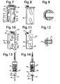
- Les
figures 1 et 2 sont deux vues en élévation, à 90° l'une de l'autre, d'un embout de préhension et de vissage selon l'invention dans lequel les mors sont en position déployée ; - La
figure 3 est une coupe selon AA' de lafigure 2 ; - Les
figures 4 à 6 sont des vues analogues à celles desfigures 1 à 3 , mais dans lesquelles les mors sont en position rétractée ; - La
figure 7 est une vue en perspective d'un mors femelle ; - La
figure 8 est une vue de côté du mors représentéfigure 7 ; - La
figure 9 est une vue d'extrémité, côté collerette du mors femelle ; - Les
figures 10 à 12 représentent un mors mâle respectivement en perspective (figure 10 ), en élévation (figure 11 ) et en vue d'extrémité côté collerette (figure 12 ) ; - Les
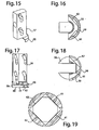
figures 13 et 14 sont des vues respectivement en élévation (figure 13 ) et en coupe axiale selon BB' de lafigure 13 (figure 14 ) d'une variante d'exécution d'un embout de préhension et de vissage selon l'invention. - Les
figures 15 et 16 représentent en perspective (figure 15 ) et en vue d'extrémité (figure 16 ) un mors de type mâle de l'embout illustré sur lesfigures 13 et 14 ; - Les
figures 17 et 18 représentent en perspective (figure 17 ) et en vue d'extrémité (figure 18 ) un mors de type femelle de l'embout illustré sur lesfigures 13 et 14 ; - La
figure 19 est une représentation schématique montrant la position de la section polygonale de la tête de la vis dans les empreintes des mors de l'embout représenté sur lesfigures 13 à 18 .
- The
Figures 1 and 2 are two views in elevation, at 90 ° from each other, of a gripping and screwing tip according to the invention in which the jaws are in the deployed position; - The
figure 3 is a cup according to AA 'of thefigure 2 ; - The
Figures 4 to 6 are views similar to those ofFigures 1 to 3 but in which the jaws are in the retracted position; - The
figure 7 is a perspective view of a female jaw; - The
figure 8 is a side view of the bit shownfigure 7 ; - The
figure 9 is an end view, flange side of the female jaw; - The
Figures 10 to 12 represent a male jaw respectively in perspective (figure 10 ), in elevation (figure 11 ) and end view flange side (figure 12 ); - The
Figures 13 and 14 are respectively elevation views (figure 13 ) and in axial section along BB 'of theFigure 13 (Figure 14 ) of an alternative embodiment of a gripping and screwing tip according to the invention. - The
Figures 15 and 16 represent in perspective (figure 15 ) and in end view (figure 16 ) a male-type jaw of the tip shown on theFigures 13 and 14 ; - The
Figures 17 and 18 represent in perspective (figure 17 ) and in end view (figure 18 ) a female type jaw of the tip shown on theFigures 13 and 14 ; - The
figure 19 is a schematic representation showing the position of the polygonal section of the screw head in the fingerprints of the jaw of the tip shown in FIGS.Figures 13 to 18 .
Dans l'exemple représenté sur les
Cette tête 1 est reliée à une tige coaxiale 7 par l'intermédiaire d'une portion cylindrique sous tête 8 dont le diamètre est sensiblement égal à la distance entre le fond des échancrures et l'axe XX' de la vis.This
Dans cet exemple, la hauteur de la portion cylindrique 8 est sensiblement égale à la hauteur du bord périphérique 3 de la tête 1. Le diamètre de la tige 7 de la vis au niveau de son raccordement à la portion cylindrique 8 est très inférieur à celui de la tête 1 (environ 50%), le raccord entre la portion cylindrique 8 avec le bord périphérique 3 de la tête 1 et avec l'extrémité de la tige 7 s'effectuant grâce à des épaulements radiaux.In this example, the height of the
Dans cet exemple, la tige 7 de la vis présente un filet auto taraudeur 4 terminé par une pointe auto perforante 5.In this example, the rod 7 of the screw has a self-tapping thread 4 terminated by a self-piercing tip 5.
Bien entendu, l'invention ne se limite pas à un type de filet ou de pointe particulier.Of course, the invention is not limited to a particular type of net or tip.
Cette vis peut être vissée à l'aide d'un outil à main présentant un embout tubulaire dont le profil intérieur correspond à la forme extérieure dentelée de la tête 1.This screw can be screwed using a hand tool having a tubular nozzle whose inner profile corresponds to the outer serrated shape of the
Néanmoins, elle convient tout particulièrement à l'embout de vissage illustré sur les
Cette douille 10 délimite une cavité cylindrique coaxiale 13 débouchant à l'extérieur à l'opposé du fond 11. La paroi cylindrique de cette cavité 13 est lisse et ne comprend aucun élément en saillie tel que par exemple, une rampe.This
A l'intérieur de cette douille 10, est disposé un mécanisme de préhension 14 mobile axialement, qui comprend deux mors 15, 16 dont l'un 15 est de type mâle, tandis que l'autre 16 est de type femelle.Inside this
Le mors 15 de type mâle présente un corps parallélépipédique 17, axialement allongé comprenant un côté latéral cylindrique 18.The male-
Ce corps 17 est prolongé, à l'une de ses extrémités, par une fraction de collerette 19 qui s'étend coaxialement au côté latéral 18 en saillie relativement à celui-ci et qui présente un diamètre extérieur sensiblement égal au diamètre intérieur de la douille 10.This
La surface intérieure de cette fraction de collerette 19 comprend successivement, en partant du corps 17, dans le sens axial :
une portion dentelée 20 en forme de secteur de couronne, cette portion dentelée étant sensiblement complémentaire au bord périphérique dentelé de la tête 1 de la vis, et- une portion lisse cylindrique de diamètre inférieur à celui de la
portion dentelée 20 et de préférence égal au diamètre de la portion cylindrique 7 sous tête de la vis.
- a
toothed portion 20 in the form of a sector of crown, this serrated portion being substantially complementary to the serrated peripheral edge of thehead 1 of the screw, and - a smooth cylindrical portion of smaller diameter than the
toothed portion 20 and preferably equal to the diameter of the cylindrical portion 7 under the head of the screw.
La face du corps 17 adjacente à la collerette 19 présente un étagement 22 formant un décrochement à profil circulaire.The face of the
Le mors de type femelle 16 (
Ce corps 23 est muni d'une cavité axiale parallélépipédique 24 sensiblement complémentaire au corps 17 du mors 15 de type mâle qui est destiné à venir s'y loger.This
Le corps 23 est prolongé, d'un côté par un évasement 25 en forme de congé, lui-même axialement prolongé sur une partie de sa périphérie par une fraction de collerette 26 similaire à celle du mors 15 de type mâle et comprenant d'une façon analogue une portion dentelée 20' et une portion lisse cylindrique 21'. Cette fraction de collerette 26 est centrée à l'opposé de l'ouverture axiale de la cavité 24 de sorte que lorsque le corps 17 du mors 15 de type mâle est engagé dans la cavité 24 du corps 23 du mors 16 de type femelle, les deux fractions de collerette 19, 26 se font face et se trouvent inscrites dans un même cercle extérieur.The
Le volume intérieur de la douille 10 est traversé par deux broches radiales 30, 31 axialement décalées dont les extrémités s'engagent dans des perçages correspondants prévus dans la douille 10.The internal volume of the
Ces deux broches sont destinées à passer au travers de perçages oblongs traversants 32, 33 - 34,35 - 34', 35' réalisés dans le corps des mors 15, 16 de type mâle et femelle.These two pins are intended to pass through oblong through
A cet effet, le mors de type mâle 15 comprend deux perçages oblongs traversants 32, 33 réalisés entre les deux faces principales du corps 17.For this purpose, the male-
Par contre, le mors 16 de type femelle comprend deux couples de perçages oblongs coaxiaux 34, 34' - 35, 35', radialement traversants débouchant dans les deux faces opposées de la cavité axiale 24.On the other hand, the
Ces deux couples de perçages oblongs 34, 34' - 35, 35' sont disposés de manière à ce que, lorsque le corps 17 du mors 15 de type mâle est engagé dans la cavité axiale 24 du corps 23 du mors 16 de type femelle, les perçages oblongs coaxiaux de chaque couple 34, 34' - 35, 35' se trouvent alignés localement avec un perçage oblong 32, 33 du corps 17 du mors 15 de type mâle en délimitant un passage dans lequel s'engage l'une desdites broches 30, 31.These two pairs of
Les perçages oblongs 32 à 35 et 34', 35' comprennent chacun une portion P1 qui s'étend axialement et une portion P2 qui s'étend obliquement par rapport à l'axe longitudinal de la douille 10.The oblong holes 32 to 35 and 34 ', 35' each comprise a portion P 1 which extends axially and a portion P 2 which extends obliquely with respect to the longitudinal axis of the
Les portions obliques P2 des perçages oblongs d'un même mors s'étendent parallèlement les unes des autres.The oblique portions P 2 oblong holes of the same jaw extend parallel to each other.
Par contre, les portions obliques P2 des perçages oblongs 32, 33 du mors 15 de type mâle sont orientées à l'opposé des portions obliques P2 des perçages oblongs 34, 35 - 34', 35' du mors 16 de type femelle.On the other hand, the oblique portions P 2 of the oblong holes 32, 33 of the
Par ailleurs, les corps 17, 23 des mors 15, 16 de type mâle et femelle présentent deux perçages radiaux traversants 40, 41 axés perpendiculairement aux broches et dans lesquels s'engage un axe servant à solidariser axialement les deux mors 15, 16 tout en autorisant leur translation radiale.Furthermore, the
Un ressort 42 disposé coaxialement à l'axe exerce alors sur les mors un effort tendant à les ouvrir.A
Grâce à ces dispositions, un déplacement axial des mors de type mâle 15 et femelle 16 depuis la position déployée des mors (
- une rétraction progressive des deux mors provoquée par l'action des deux broches 30, 31 sur les portions obliques P2 des perçages oblongs 32 à 35 - 34', 35' ; cette rétraction s'effectue par une double translation axiale et radiale sans qu'il n'y ait une quelconque rotation ou basculement (la géométrie du dispositif ne le permet pas) ;
- une fois que les deux mors 15, 16 sont totalement engagés l'un dans l'autre, la collerette se trouvant encore à l'extérieur de la cavité de la douille, une translation axiale des mors 15, 16 jusqu'à ce que les fractions de collerette 19, 26 se trouvent au moins en partie engagées dans la cavité de la douille 10 ; dans cette position, les fractions de collerette 19, 26 se trouvent radialement verrouillées par la douille 10.
- a progressive retraction of the two jaws caused by the action of the two
pins oblong holes 32 to 35 - 34 ', 35'; this retraction is effected by a double axial and radial translation without there being any rotation or tilting (the geometry of the device does not allow it); - once the two
jaws jaws flange fractions sleeve 10; in this position, theflange fractions sleeve 10.
Grâce à ces dispositions, à partir de la disposition de l'embout illustré sur les
Cette poussée provoque un déplacement en translation des mors 15, 16 qui passent à l'état rétracté, tandis que les fractions de collerette 19, 26 viennent emprisonner la bordure de la tête 1 de la vis en deux zones diamétralement opposées. Parallèlement, les dentures des fractions de collerette 19, 26 s'engagent entre les dentures de la tête 1 de la vis en assurant une solidarisation en rotation par complémentarité de forme.This thrust causes a translational movement of the
En fin de translation axiale, les fractions de collerette 19, 26 s'engagent étroitement à l'intérieur de la douille 10 et se trouvent donc radialement verrouillées.At the end of axial translation, the
L'opérateur peut alors procéder au vissage de la vis. En fin de vissage, l'opérateur exerce une traction axiale sur l'embout, ce qui provoque un déplacement des mors 15, 16 en sens inverse et leur passage en position déployée avec désengagement de la tête 1 de la vis.The operator can then proceed to screw the screw. At the end of screwing, the operator exerts an axial traction on the tip, which causes a displacement of the
Cette solution s'avère particulièrement efficace et permet de réaliser des embouts de préhension présentant une grande compacité.This solution is particularly effective and allows for gripping tips with a high compactness.
En outre, en position verrouillée, les broches ne coopèrent qu'avec les portions axiales des perçages oblongs, de sorte qu'un processus de déploiement intempestif des mors (dû à la réversibilité d'un montage à rampe) ne peut pas se produire.In addition, in the locked position, the pins cooperate only with the axial portions of the oblong holes, so that a process of inadvertent deployment of the jaws (due to the reversibility of a ramp assembly) can not occur.
Par ailleurs, la transmission du couple entre la douille 10 et les mors 15, 16, qui est assurée par les deux broches (30,31), s'effectue dans des conditions optimales.Furthermore, the transmission of the torque between the
Les
Dans cet exemple, les éléments de l'embout 54 sont strictement identiques à ceux de l'embout précédemment décrit, à l'exception des fractions de collerette 55, 56 qui, dans ce cas, s'étendent sur près de 180° (environ 170°) et qui comprennent chacune, successivement, à partir du corps 57, 58 des mors :
- une cavité annulaire 59 (
figure 17 ) qui s'étend sur une fraction de circonférence de diamètre sensiblement égal au diamètre de la calotte 52 de la tête 51 de la vis 50 ; cette cavité annulaire pourra comprendre une forme conique sensiblement complémentaire de la couronne conique de la calotte 52 de la tête 51 de la vis 50, et une empreinte 60 comportant deux facettes 61, 62 s'étendant à 90° l'une de l'autre et disposées symétriquement par rapport à un plan bissecteur passant par l'axe de l'embout, ce plan bissecteur constituant un plan de symétrie également pour la cavité annulaire 59.
- an annular cavity 59 (
figure 17 ) which extends over a fraction of circumference of diameter substantially equal to the diameter of thecap 52 of thehead 51 of thescrew 50; this annular cavity may comprise a conical shape substantially complementary to the conical crown of thecap 52 of thehead 51 of thescrew 50, and - an
impression 60 comprising twofacets annular cavity 59.
Le fonctionnement de cette douille est similaire à celui de la douille précédemment décrite.The operation of this socket is similar to that of the sleeve described above.
Ainsi, à partir de la position déployée illustrée sur la
Une fois en position rétractée, les fractions de collerette 55, 56 s'engagent au moins partiellement à l'intérieur de la douille 62 et se trouvent alors verrouillées radialement.Once in the retracted position, the
L'avantage de cette solution (de même que dans la précédente) consiste en ce qu'elle autorise de légères variations dimensionnelles des têtes des vis sans que cela nuise au bon fonctionnement de la douille. En effet, selon ces variations dimensionnelles, la tête 51 de la vis 50 s'engagera plus ou moins profondément dans les empreintes 60 et la cavité annulaire 59 des mors, tout en étant correctement centrée. Bien entendu, il conviendra à cet effet de prévoir un léger jeu entre la surface extérieure des fractions de collerette 55, 56 et la surface intérieure de la douille 63.The advantage of this solution (as in the previous one) is that it allows slight dimensional variations of the screw heads without affecting the proper operation of the socket. Indeed, according to these dimensional variations, the
Ce léger jeu n'aura aucune incidence sur le fonctionnement de l'embout puisque, lors de la rotation de l'embout, le couple résistant exercé par la vis provoquera sur les fractions de collerette des mors, un effort tendant à les appliquer fermement sur la surface intérieure de la douille en assurant ainsi un rattrapage automatique de jeu.This slight clearance will have no effect on the operation of the tip since, during the rotation of the tip, the resistant torque exerted by the screw will cause the collet fractions of the jaws, a force tending to apply firmly on the inner surface of the socket thus ensuring an automatic adjustment of play.
Claims (11)
- Gripping and screwing bit for a screw of which the head (1) has on its periphery structures intended to cooperate with a screwing tool, on the one hand, in order to provide an axial securing between the tool and the screw and, on the other hand, in order to allow the tool to exert on the screw a screwing torque, comprising- a sleeve (10) having, on one side, means for driving in rotation (12) and, on the other side, a coaxial cavity (13) exiting outside via a circular orifice,- a gripping mechanism (14) which can move axially inside said cavity (13), this mechanism comprising two jaws (15, 16) which can move translationally with respect to one another, according to a radial plane,- structures (20, 20') provided at the end of the jaws (15, 16) to allow for an engagement of the head (1) of the screw, in the separated position of the jaws (15, 16), then the grasping of said head (1) by its peripheral edge with securing in rotation of said head (1) and of said jaws (15, 16), by shape complementarity, when said jaws (15, 16) are in retracted position, returned at least partially inside said sleeve (10),- conversion means able to control the radial translation of the two jaws (15, 16) following an axial movement of the gripping mechanism (14), in such a way as to change from an open position, in which the two jaws (15, 16) are separated from one another and extend outside the sleeve (10), to a closed position in which the two jaws (15, 16) are retracted and are returned inside the sleeve (10),
characterised in that- the aforementioned conversion means cause to intervene:- on the one hand, two radial parallel axially offset pins (30, 31) passing through the cavity of the sleeve (10) and engaging respectively into two pairs of coaxial perforations provided in the sleeve (10),- on the other hand, at least two oblong perforations radially passing (32, 33 - 34, 35 - 34', 35'), respectively provided in each jaw (15, 16), these oblong perforations (32, 33 - 34, 35 - 34', 35') arranged in such a way as to be two by two in coincidence and to delimit two radial passages through which the two pins (30, 31) engage respectively.- each of the oblong perforations (32, 33 - 34, 35 - 34', 35') comprises an axial portion (P1) followed by an oblique portion (P2), the oblique portions (P2) of two oblong perforations in coincidence through which passes the same pin being oriented opposite from one another,- the transmission of the torque between the sleeve (10) and the jaws (15, 16) is provided by the two pins (3 0, 31). - Bit according to claim 1,
characterised in that the two jaws (15, 16) each have an extended body terminated, on one side, by a fraction of a circular skirt (19, 26) having the aforementioned structures (20, 20'). - Bit according to claim 2,
characterised in that one of the jaws (16) is of the female type, and in that the other jaw (15) is of the male type and is engaged slidingly in the jaw (16) of the female type. - Bit according to claim 3,
characterised in that the jaw (16) of the female type comprises a cylindrically-shaped body (23) provided with an axial cavity (24) of rectangular section, and in that the jaw (15) of the male type comprises a body (17) of parallelepiped shape with a section substantially complementary with that of the axial cavity (24) wherein it becomes engaged and can slide radially. - Bit according to claim 2,
characterised in that in the retracted position of the jaws (15, 16), the aforementioned fractions of circular skirt (19, 26) extend in the extension one in relation to the other. - Bit according to one of the preceding claims,
characterised in that the two jaws (15, 16) include at least two coaxial radial perforations (40, 41) on axes perpendicular to said pins (30, 31) and wherein is engaged a guide axis allowing for a radial displacement in translation of the two jaws (15, 16). - Bit according to claim 6,
characterised in that it comprises a spring (42) generating on the two jaws, a force tending to separate one from the other. - Bit according to claim 2,
characterised in that, in the returned position of the jaws (15, 16), the fractions of skirt (19, 26) are at least partially engaged in the sleeve (10). - Bit according to claim 3,
characterised in that the fractions of skirt (19, 26) of the jaws of the male and female type (15, 16) include successively, starting from the body (17, 23), a toothed portion (20, 20') in the shape of a crown sector, this toothed portion being substantially complementary with the peripheral edge of the head (1) of the screw and a smooth cylindrical portion of a diameter less than that of the toothed portion (20) and more preferably equal to the diameter of the cylindrical portion (7) under the head of the screw. - Bit according to claim 2, intended for a screw (50) of which the head has a dome followed by a portion under the head (53) of polygonal section which extends coaxially to the screw,
characterised in that the fractions of skirt (55, 56) each include, successively starting from the body of said jaws:- an annular cavity (59) which extends over a fraction of the circumference of a diameter substantially equal to the diameter of the dome (52) of the head (51) of the screw (50) and,- an imprint (60) comprising two faces (61, 62) extending 90° in relation to one another and arranged symmetrically in relation to a bisecting plane passing through the axis of the bit. - Bit according to claim 10,
characterised in that the dome (52) of the head (51) of the screw (50) is terminated by a tapered crown, and in that the aforementioned annular cavity comprises a tapered shape that is substantially complementary with the tapered crown of the dome (52) of the head (51) of the screw (50).
Priority Applications (1)
| Application Number | Priority Date | Filing Date | Title |
|---|---|---|---|
| PL09728518T PL2265411T3 (en) | 2008-03-13 | 2009-02-26 | Gripping and screwing bit intended to equip a screwing device |
Applications Claiming Priority (2)
| Application Number | Priority Date | Filing Date | Title |
|---|---|---|---|
| FR0801371A FR2928574B1 (en) | 2008-03-13 | 2008-03-13 | PRETENSION AND SCREWING BIT FOR EQUIPPING A SCREWDRIVER. |
| PCT/FR2009/000219 WO2009122025A1 (en) | 2008-03-13 | 2009-02-26 | Gripping and screwing bit intended to equip a screwing device |
Publications (2)
| Publication Number | Publication Date |
|---|---|
| EP2265411A1 EP2265411A1 (en) | 2010-12-29 |
| EP2265411B1 true EP2265411B1 (en) | 2011-06-29 |
Family
ID=39874052
Family Applications (1)
| Application Number | Title | Priority Date | Filing Date |
|---|---|---|---|
| EP09728518A Active EP2265411B1 (en) | 2008-03-13 | 2009-02-26 | Gripping and screwing bit intended to equip a screwing device |
Country Status (6)
| Country | Link |
|---|---|
| EP (1) | EP2265411B1 (en) |
| AT (1) | ATE514529T1 (en) |
| ES (1) | ES2369067T3 (en) |
| FR (1) | FR2928574B1 (en) |
| PL (1) | PL2265411T3 (en) |
| WO (1) | WO2009122025A1 (en) |
Families Citing this family (2)
| Publication number | Priority date | Publication date | Assignee | Title |
|---|---|---|---|---|
| US11203228B2 (en) | 2020-03-15 | 2021-12-21 | Robotire, Inc. | Lug nut holder and method of use |
| CN114310759A (en) * | 2020-10-12 | 2022-04-12 | 许纮佾 | Locking sleeve with auxiliary locking |
Family Cites Families (5)
| Publication number | Priority date | Publication date | Assignee | Title |
|---|---|---|---|---|
| US1155662A (en) * | 1914-08-10 | 1915-10-05 | William J Kleinsteuber | Clamping device. |
| US2850931A (en) * | 1957-01-03 | 1958-09-09 | Conway James | Cam-closed, slidable jaw wrench |
| US4520698A (en) * | 1984-01-18 | 1985-06-04 | Martinmaas Werner W | Adjustable socket for socket wrenches |
| US5375489A (en) * | 1992-12-11 | 1994-12-27 | Mcclure; Travis | Self-locking universal socket tool |
| US7261021B1 (en) * | 2006-02-18 | 2007-08-28 | Thomas Carnesi | Adjustable socket |
-
2008
- 2008-03-13 FR FR0801371A patent/FR2928574B1/en active Active
-
2009
- 2009-02-26 ES ES09728518T patent/ES2369067T3/en active Active
- 2009-02-26 AT AT09728518T patent/ATE514529T1/en not_active IP Right Cessation
- 2009-02-26 WO PCT/FR2009/000219 patent/WO2009122025A1/en active Application Filing
- 2009-02-26 EP EP09728518A patent/EP2265411B1/en active Active
- 2009-02-26 PL PL09728518T patent/PL2265411T3/en unknown
Also Published As
| Publication number | Publication date |
|---|---|
| FR2928574B1 (en) | 2012-03-09 |
| PL2265411T3 (en) | 2012-03-30 |
| ATE514529T1 (en) | 2011-07-15 |
| WO2009122025A1 (en) | 2009-10-08 |
| ES2369067T3 (en) | 2011-11-25 |
| EP2265411A1 (en) | 2010-12-29 |
| FR2928574A1 (en) | 2009-09-18 |
Similar Documents
| Publication | Publication Date | Title |
|---|---|---|
| CA2830575C (en) | Shut-off device with automatically activatable locking | |
| EP1961531B1 (en) | Tightening device with a retractable manoeuvring arm and apparatus including such a device | |
| FR2847180A1 (en) | TOOL HOLDER CHUCK WITH LOCKING SYSTEM | |
| EP2389264B1 (en) | Tool holder mandrel for equipping a rotating machine | |
| EP0723086A1 (en) | Screw with a separable head and screwing tool for such a screw | |
| FR2857080A1 (en) | Locking device for channel connector, has ratchet type teeth permitting rotation of male and female units with respect to one another relative to unscrewing direction when predetermined elastic resistance of compression spring is overcome | |
| EP1118401A1 (en) | Expanding device for forming bells at tube ends | |
| EP2265411B1 (en) | Gripping and screwing bit intended to equip a screwing device | |
| EP1292527B1 (en) | Screwing spindle | |
| EP1553310B1 (en) | A reversible device for locking an end piece on a structure with adjustable position | |
| EP1540229A1 (en) | Clamping ring | |
| EP1722929B1 (en) | Grasping clamping end for a screwing device | |
| EP0268510B1 (en) | Blind-fastening device for the assembly of at least two pieces such as sheets of metal | |
| EP1382863B1 (en) | Screw with a head specially adapted to a tool bit for holding and screwing it | |
| EP1382418A1 (en) | Schraubvorrichtung bestehend aus einer Schraube mit Spezialkopf und einem für diesen Kopf geeigneten Steckschlüssel | |
| WO2017216504A1 (en) | Quick-release setting tool for an element to be crimped | |
| FR2626187A1 (en) | Method and device for assembling the end of a tubular shaft of a golf club and a neck integral with the head of this club, and golf club obtained by this method | |
| FR2925627A1 (en) | FIXING DEVICE AND METHOD FOR CLAMPING A WORKPIECE. | |
| EP2922664A2 (en) | Device for facilitating the insertion of a piston with the segments thereof into a cylinder of a vehicle engine | |
| FR2843062A1 (en) | Gripper sleeve for fastener driver has shaft with movable jaw mounted in end bore and O-ring to retain jaw | |
| FR2533158A1 (en) | Mechanism for driving a tool in rotation step by step, in particular for nut spanners | |
| WO2001023145A1 (en) | Rotational driving tool for screwing member | |
| FR2648381A1 (en) | Tool for fitting and removing pinning clamps | |
| EP0782950A1 (en) | Steering wheel and column adapted for mounting such a wheel | |
| FR2883210A1 (en) | Mandrel for holding tool, e.g. drill bit, for turning machine, includes central piece having holding jaws and rear operating collar with blocked relative rotation and axial translation |
Legal Events
| Date | Code | Title | Description |
|---|---|---|---|
| PUAI | Public reference made under article 153(3) epc to a published international application that has entered the european phase |
Free format text: ORIGINAL CODE: 0009012 |
|
| 17P | Request for examination filed |
Effective date: 20100831 |
|
| AK | Designated contracting states |
Kind code of ref document: A1 Designated state(s): AT BE BG CH CY CZ DE DK EE ES FI FR GB GR HR HU IE IS IT LI LT LU LV MC MK MT NL NO PL PT RO SE SI SK TR |
|
| AX | Request for extension of the european patent |
Extension state: AL BA RS |
|
| GRAP | Despatch of communication of intention to grant a patent |
Free format text: ORIGINAL CODE: EPIDOSNIGR1 |
|
| DAX | Request for extension of the european patent (deleted) | ||
| GRAS | Grant fee paid |
Free format text: ORIGINAL CODE: EPIDOSNIGR3 |
|
| GRAA | (expected) grant |
Free format text: ORIGINAL CODE: 0009210 |
|
| AK | Designated contracting states |
Kind code of ref document: B1 Designated state(s): AT BE BG CH CY CZ DE DK EE ES FI FR GB GR HR HU IE IS IT LI LT LU LV MC MK MT NL NO PL PT RO SE SI SK TR |
|
| REG | Reference to a national code |
Ref country code: GB Ref legal event code: FG4D Free format text: NOT ENGLISH |
|
| REG | Reference to a national code |
Ref country code: CH Ref legal event code: EP |
|
| REG | Reference to a national code |
Ref country code: IE Ref legal event code: FG4D Free format text: LANGUAGE OF EP DOCUMENT: FRENCH |
|
| REG | Reference to a national code |
Ref country code: RO Ref legal event code: EPE |
|
| REG | Reference to a national code |
Ref country code: DE Ref legal event code: R096 Ref document number: 602009001700 Country of ref document: DE Effective date: 20110908 |
|
| REG | Reference to a national code |
Ref country code: NL Ref legal event code: T3 |
|
| PG25 | Lapsed in a contracting state [announced via postgrant information from national office to epo] |
Ref country code: SE Free format text: LAPSE BECAUSE OF FAILURE TO SUBMIT A TRANSLATION OF THE DESCRIPTION OR TO PAY THE FEE WITHIN THE PRESCRIBED TIME-LIMIT Effective date: 20110629 Ref country code: NO Free format text: LAPSE BECAUSE OF FAILURE TO SUBMIT A TRANSLATION OF THE DESCRIPTION OR TO PAY THE FEE WITHIN THE PRESCRIBED TIME-LIMIT Effective date: 20110929 Ref country code: HR Free format text: LAPSE BECAUSE OF FAILURE TO SUBMIT A TRANSLATION OF THE DESCRIPTION OR TO PAY THE FEE WITHIN THE PRESCRIBED TIME-LIMIT Effective date: 20110629 Ref country code: LT Free format text: LAPSE BECAUSE OF FAILURE TO SUBMIT A TRANSLATION OF THE DESCRIPTION OR TO PAY THE FEE WITHIN THE PRESCRIBED TIME-LIMIT Effective date: 20110629 |
|
| REG | Reference to a national code |
Ref country code: ES Ref legal event code: FG2A Ref document number: 2369067 Country of ref document: ES Kind code of ref document: T3 Effective date: 20111125 |
|
| PG25 | Lapsed in a contracting state [announced via postgrant information from national office to epo] |
Ref country code: LV Free format text: LAPSE BECAUSE OF FAILURE TO SUBMIT A TRANSLATION OF THE DESCRIPTION OR TO PAY THE FEE WITHIN THE PRESCRIBED TIME-LIMIT Effective date: 20110629 Ref country code: FI Free format text: LAPSE BECAUSE OF FAILURE TO SUBMIT A TRANSLATION OF THE DESCRIPTION OR TO PAY THE FEE WITHIN THE PRESCRIBED TIME-LIMIT Effective date: 20110629 Ref country code: AT Free format text: LAPSE BECAUSE OF FAILURE TO SUBMIT A TRANSLATION OF THE DESCRIPTION OR TO PAY THE FEE WITHIN THE PRESCRIBED TIME-LIMIT Effective date: 20110629 Ref country code: GR Free format text: LAPSE BECAUSE OF FAILURE TO SUBMIT A TRANSLATION OF THE DESCRIPTION OR TO PAY THE FEE WITHIN THE PRESCRIBED TIME-LIMIT Effective date: 20110930 Ref country code: SI Free format text: LAPSE BECAUSE OF FAILURE TO SUBMIT A TRANSLATION OF THE DESCRIPTION OR TO PAY THE FEE WITHIN THE PRESCRIBED TIME-LIMIT Effective date: 20110629 |
|
| REG | Reference to a national code |
Ref country code: IE Ref legal event code: FD4D |
|
| PG25 | Lapsed in a contracting state [announced via postgrant information from national office to epo] |
Ref country code: IE Free format text: LAPSE BECAUSE OF FAILURE TO SUBMIT A TRANSLATION OF THE DESCRIPTION OR TO PAY THE FEE WITHIN THE PRESCRIBED TIME-LIMIT Effective date: 20110629 Ref country code: PT Free format text: LAPSE BECAUSE OF FAILURE TO SUBMIT A TRANSLATION OF THE DESCRIPTION OR TO PAY THE FEE WITHIN THE PRESCRIBED TIME-LIMIT Effective date: 20111031 Ref country code: IS Free format text: LAPSE BECAUSE OF FAILURE TO SUBMIT A TRANSLATION OF THE DESCRIPTION OR TO PAY THE FEE WITHIN THE PRESCRIBED TIME-LIMIT Effective date: 20111029 Ref country code: EE Free format text: LAPSE BECAUSE OF FAILURE TO SUBMIT A TRANSLATION OF THE DESCRIPTION OR TO PAY THE FEE WITHIN THE PRESCRIBED TIME-LIMIT Effective date: 20110629 |
|
| PG25 | Lapsed in a contracting state [announced via postgrant information from national office to epo] |
Ref country code: SK Free format text: LAPSE BECAUSE OF FAILURE TO SUBMIT A TRANSLATION OF THE DESCRIPTION OR TO PAY THE FEE WITHIN THE PRESCRIBED TIME-LIMIT Effective date: 20110629 Ref country code: CY Free format text: LAPSE BECAUSE OF FAILURE TO SUBMIT A TRANSLATION OF THE DESCRIPTION OR TO PAY THE FEE WITHIN THE PRESCRIBED TIME-LIMIT Effective date: 20110629 |
|
| REG | Reference to a national code |
Ref country code: PL Ref legal event code: T3 |
|
| PLBE | No opposition filed within time limit |
Free format text: ORIGINAL CODE: 0009261 |
|
| STAA | Information on the status of an ep patent application or granted ep patent |
Free format text: STATUS: NO OPPOSITION FILED WITHIN TIME LIMIT |
|
| 26N | No opposition filed |
Effective date: 20120330 |
|
| PG25 | Lapsed in a contracting state [announced via postgrant information from national office to epo] |
Ref country code: DK Free format text: LAPSE BECAUSE OF FAILURE TO SUBMIT A TRANSLATION OF THE DESCRIPTION OR TO PAY THE FEE WITHIN THE PRESCRIBED TIME-LIMIT Effective date: 20110629 |
|
| REG | Reference to a national code |
Ref country code: DE Ref legal event code: R097 Ref document number: 602009001700 Country of ref document: DE Effective date: 20120330 |
|
| PG25 | Lapsed in a contracting state [announced via postgrant information from national office to epo] |
Ref country code: MC Free format text: LAPSE BECAUSE OF NON-PAYMENT OF DUE FEES Effective date: 20120229 |
|
| PG25 | Lapsed in a contracting state [announced via postgrant information from national office to epo] |
Ref country code: MK Free format text: LAPSE BECAUSE OF FAILURE TO SUBMIT A TRANSLATION OF THE DESCRIPTION OR TO PAY THE FEE WITHIN THE PRESCRIBED TIME-LIMIT Effective date: 20110629 |
|
| PG25 | Lapsed in a contracting state [announced via postgrant information from national office to epo] |
Ref country code: BG Free format text: LAPSE BECAUSE OF FAILURE TO SUBMIT A TRANSLATION OF THE DESCRIPTION OR TO PAY THE FEE WITHIN THE PRESCRIBED TIME-LIMIT Effective date: 20110929 |
|
| PG25 | Lapsed in a contracting state [announced via postgrant information from national office to epo] |
Ref country code: MT Free format text: LAPSE BECAUSE OF FAILURE TO SUBMIT A TRANSLATION OF THE DESCRIPTION OR TO PAY THE FEE WITHIN THE PRESCRIBED TIME-LIMIT Effective date: 20110629 |
|
| REG | Reference to a national code |
Ref country code: CH Ref legal event code: PL |
|
| GBPC | Gb: european patent ceased through non-payment of renewal fee |
Effective date: 20130226 |
|
| PG25 | Lapsed in a contracting state [announced via postgrant information from national office to epo] |
Ref country code: CH Free format text: LAPSE BECAUSE OF NON-PAYMENT OF DUE FEES Effective date: 20130228 Ref country code: LI Free format text: LAPSE BECAUSE OF NON-PAYMENT OF DUE FEES Effective date: 20130228 |
|
| PG25 | Lapsed in a contracting state [announced via postgrant information from national office to epo] |
Ref country code: GB Free format text: LAPSE BECAUSE OF NON-PAYMENT OF DUE FEES Effective date: 20130226 |
|
| PG25 | Lapsed in a contracting state [announced via postgrant information from national office to epo] |
Ref country code: TR Free format text: LAPSE BECAUSE OF FAILURE TO SUBMIT A TRANSLATION OF THE DESCRIPTION OR TO PAY THE FEE WITHIN THE PRESCRIBED TIME-LIMIT Effective date: 20110629 |
|
| PG25 | Lapsed in a contracting state [announced via postgrant information from national office to epo] |
Ref country code: LU Free format text: LAPSE BECAUSE OF NON-PAYMENT OF DUE FEES Effective date: 20120226 |
|
| PG25 | Lapsed in a contracting state [announced via postgrant information from national office to epo] |
Ref country code: HU Free format text: LAPSE BECAUSE OF FAILURE TO SUBMIT A TRANSLATION OF THE DESCRIPTION OR TO PAY THE FEE WITHIN THE PRESCRIBED TIME-LIMIT Effective date: 20090226 |
|
| REG | Reference to a national code |
Ref country code: FR Ref legal event code: PLFP Year of fee payment: 8 |
|
| REG | Reference to a national code |
Ref country code: FR Ref legal event code: PLFP Year of fee payment: 9 |
|
| REG | Reference to a national code |
Ref country code: FR Ref legal event code: PLFP Year of fee payment: 10 |
|
| PGFP | Annual fee paid to national office [announced via postgrant information from national office to epo] |
Ref country code: NL Payment date: 20230227 Year of fee payment: 15 |
|
| PGFP | Annual fee paid to national office [announced via postgrant information from national office to epo] |
Ref country code: RO Payment date: 20230214 Year of fee payment: 15 Ref country code: FR Payment date: 20230227 Year of fee payment: 15 Ref country code: CZ Payment date: 20230203 Year of fee payment: 15 |
|
| PGFP | Annual fee paid to national office [announced via postgrant information from national office to epo] |
Ref country code: PL Payment date: 20230203 Year of fee payment: 15 Ref country code: IT Payment date: 20230227 Year of fee payment: 15 Ref country code: DE Payment date: 20230227 Year of fee payment: 15 Ref country code: BE Payment date: 20230227 Year of fee payment: 15 |
|
| P01 | Opt-out of the competence of the unified patent court (upc) registered |
Effective date: 20230526 |
|
| PGFP | Annual fee paid to national office [announced via postgrant information from national office to epo] |
Ref country code: ES Payment date: 20230405 Year of fee payment: 15 |