EP1106737A2 - Quai - Google Patents
Quai Download PDFInfo
- Publication number
- EP1106737A2 EP1106737A2 EP00122625A EP00122625A EP1106737A2 EP 1106737 A2 EP1106737 A2 EP 1106737A2 EP 00122625 A EP00122625 A EP 00122625A EP 00122625 A EP00122625 A EP 00122625A EP 1106737 A2 EP1106737 A2 EP 1106737A2
- Authority
- EP
- European Patent Office
- Prior art keywords
- platform
- plates
- foundations
- foundation
- transverse
- Prior art date
- Legal status (The legal status is an assumption and is not a legal conclusion. Google has not performed a legal analysis and makes no representation as to the accuracy of the status listed.)
- Withdrawn
Links
Images


Classifications
-
- E—FIXED CONSTRUCTIONS
- E01—CONSTRUCTION OF ROADS, RAILWAYS, OR BRIDGES
- E01F—ADDITIONAL WORK, SUCH AS EQUIPPING ROADS OR THE CONSTRUCTION OF PLATFORMS, HELICOPTER LANDING STAGES, SIGNS, SNOW FENCES, OR THE LIKE
- E01F1/00—Construction of station or like platforms or refuge islands or like islands in traffic areas, e.g. intersection or filling-station islands; Kerbs specially adapted for islands in traffic areas
Definitions
- the invention is directed to a platform with a supporting structure placed, plate-shaped prefabricated components, the supporting structure on in The longitudinal foundations of the tracks, one behind the other, rest on which each has a cross member placed on it, which is designed as a prefabricated component.
- a generic arrangement is from German laid-open publication 43 16 203 known.
- There is a kit for creating a prefabricated platform discloses, on transversely to the longitudinal direction of the platform In-situ concrete foundations first each have a support beam and then the Platform plates with molded on their underside according to cassette type, box-shaped support beams are placed.
- This type may be the meet static requirements, but is also extremely massive, in particular due to the platform slabs, which are made of cassette are therefore difficult to transport. Because part of the support beams the underside of the platform slabs themselves can be the same can be subsequently lifted at best with the heaviest lifting equipment, if, for example, the platform height is to be changed. This construction is so particularly cumbersome and hardly leaves after completion of a platform Changes to the same more.
- the Cross foundations are designed as prefabricated components with at least one top, quiver-like recess, the cross member having a bridge-like shape (U turned inside out) and each with a free end of their side legs a quiver recess of the transverse foundations are used.
- the cross members are not as solid cuboids trained, which is not necessary for structural reasons, but they have a filigree, truss-like shape, with the volume of these elements on the dimension required for structural reasons is reduced.
- the neighboring platform in question Tracks always had to be blocked for several days, for example the transverse foundations are carried out during a night break in traffic, and the placement of the further prefabricated components can, for example, in the following or the following Nights take place so that rail traffic is hardly affected during the day.
- the FT platform slabs are one to the tracks parallel length between 2 m to 8 m.
- the invention provides for the FT platform slabs standardize and keep a range of four sizes ready Lengths of 3.0 m, 4.5 m, 6.0 m and 7.5 m, so that the desired Platform length can be realized with comparatively few modules.
- a modular system can also be provided for the width of the platform slabs be, for example, platform slabs with widths of 2.5 m and 3.0 m for the construction of a Outside platform, and possibly one or more other module sizes for construction of a central platform, depending on the width of such a central platform two to four platform slabs can be arranged side by side.
- the sand between the FT transverse foundations is about a foundation width smaller than the length of an FT platform slab. Remains between the individual, adjacent platform slabs in each case only a very small gap of, for example, 1 cm, which as a space gap with a permanently elastic mass can be cast. On the other hand, there are two neighboring platform slabs with their mutually facing end faces in each case about up to the vertical center plane of the cross-foundation in question the same or on the relevant cross member. This material-saving Construction is achieved by the above distance requirement.
- the invention is characterized in that the platform to the track side and / or to the outside by elongated, in the longitudinal direction of the platform running FT plates is completed. Because of the bridge-like Supporting elements are the platform slabs of both the foundation and lifted off the terrain. On the one hand, there could be waste under this cavity accumulate, on the other hand, nest various individuals, and therefore this space is largely closed off by pre-faded panels. Because then the substructure of the platform according to the invention is hidden from view For example, even an original platform cannot be completely demolished, but can remain hidden in the platform according to the invention, whereby the Construction costs can also be reduced.
- the FT adjusting plates have approximately the same length as the FT platform slabs.
- each have a platform plate with one or two assigned positioning plates as a set are made and transported.
- the transverse foundations preferably radial be arranged with respect to the track arch, so that the platform slabs a Trapezoidal shape obtained with a longer and a shorter longitudinal edge.
- the shelves must correspond to the relevant edge length of the Be dimensioned for the platform slab.
- the FT plates on the FT foundations are particularly advantageous put on. Since the shelves do not have a supporting function, they can be realized with a small strength, so that caused by them Additional weight only moderately loaded the foundations and the same without problems can be included.
- the FT platform plates preferably protrude above the FT positioning plates. This is ensures that even in heavy rain hardly any moisture in the area can penetrate under the platform according to the invention, so that in particular Winter avoided the potentially harmful effects of heavy frost can be.
- each FT transverse foundation is a cuboid Has shape.
- Such cuboids can be built on the appropriately prepared and leveled floor of a foundation pit be, and the foundation in question is then of vertically extending Mantle surfaces surround the terrain, so that moisture penetration as difficult as possible in the foundation body.
- the Quiver recesses on the top side have a relatively wide rim, which in is able to grasp the crossmember used stably and therefore reliably to keep in an exactly upright position.
- one gets such a massive one Foundation sufficient weight so that of passing trains triggered vibrations no displacement of the foundation and / or the can bring about the load on the structure.
- the Length of the FT transverse foundations approximately the width of the FT platform slab to be accommodated minus the area overhanging the FT positioning plate (s) corresponds.
- the in one and the same foundation component top quiver recesses for both legs of the bridge-like Cross member be incorporated so that no further adjustment is necessary on site is to be an exact with the dimensions of the cross member to be placed corresponding distance between the two quiver recesses to adhere to.
- the adjustment work on site when creating a The platform according to the invention reduced to a minimum, since only one per foundation only component has to be aligned.
- the length of the FT transverse foundations smaller than half the width of the FT platform slab to be placed.
- two cross foundations are placed next to one another for each crossbeam used, each only a top quiver recess for inserting one Have side legs of the relevant cross member.
- This arrangement has the Advantage that the mass increases for the creation of a platform according to the invention moving foundation body is approximately halved, so that the adjustment work continues is relieved.
- the top quiver recess should be approximately in the middle the rectangular top of such a foundation body, so that Adequate stabilization of one used on all sides Support leg is given.
- the two cross foundations can be from each other be spaced, for example by a dimension of 0.5 to about 1.2 m, so that the Possibility arises between the foundation halves in the longitudinal direction of the platform to lay underground cable ducts, pipes or ducts.
- the invention further recommends that the height of the FT transverse foundations be approximately the same Soil frost depth (60 cm - 80 cm) corresponds. This means that subsequent relocations in particular, the platform cannot be lifted because the frost-protected one Contact surface of the transverse foundations ensures that the Quiver recesses on the top even in extreme climatic conditions.
- the arrangement according to the invention can also be optimized in that the Width of the FT transverse foundations corresponds approximately to their height. This is the Width extension of the transverse foundations in the longitudinal direction of the platform in such a way stipulated that the same on the one hand stable and tip-proof on the ground of a excavated foundation pit, which is indicated by a corresponding Dimensioning of the base area is achieved, while on the other hand the weight of the Foundation body remains reduced to the level required for stability purposes.
- the depth of the quiver recesses is approximately that of half the height of the FT transverse foundation in question. Is the depth of the Quiver recesses dimensioned too small, so the side legs of the crossmember used do not find sufficient support, so that the risk of Inclination of the cross member cannot be completely ruled out; on the other hand, a high depth of the quiver recesses means that the Area of the recess floor introduced into the relevant foundation cuboid Weight of the platform slabs not evenly distributed over the entire Base area of the foundation cuboid can be transferred, so that a maximum precise preparation of the subsurface would be required to make a partial Eliminate overloading of the foundation cuboid. All of these disadvantages can can be avoided by about half the height of the foundation cuboid in question is divided into a lower, the weight of the supporting structure and the weight Platform bearing area and in an upper, the legs of the used crossmember upright guide area.
- the arrangement according to the invention can be further developed such that the Bottom surface of the quiver recesses runs horizontally. This will result in a appropriate alignment of the foundation block a flat contact surface for created the end face of the free leg of a cross member to be used, so that it is in an indifferent balance and none at all Lateral forces are subject, which has a favorable effect on the adjustability of the same.
- An advantageous embodiment of the invention is that the Quiver recesses have a constant horizontal section. Hereby there are vertical boundary surfaces for the quiver recesses, which the inserted end of the side leg of a cross member is sufficient Can give hold.
- a particularly universal arrangement can be achieved by the Quiver recesses a rectangular, preferably square cross-section is granted.
- the cross member is about the longitudinal axis of the Torques tilting transverse foundations counteracting Boundary area on which the local Pressure load is reduced to a minimum, while that in the longitudinal direction of the Cross foundations outside or inside boundary surfaces of the Recesses remain almost force-free even with such tilting moments, so that the load on the foundations in their longitudinal direction can be neglected.
- Static tilting moments can possibly from an inclined position of the crossbeams and thus by one exact adjustment of the same can be avoided; dynamic tilting moments noteworthy amplitude could at most when bumping a rail vehicle occur, for example when derailing a train wagon.
- the forces involved will, however, predominantly run across the track direction, since the straight Track edge of the platform slabs no starting point for in the longitudinal direction of the Platform forces. Forces that occur nevertheless become sluggish The mass of the platform slabs lying one behind the other is considerably reduced and finally spread over a variety of cross foundations, so even for In the worst case, a derailed wagon is pushed while observing the Sufficient safety measures have been taken in the above dimensioning regulations are.
- the distance between the quiver recesses should be closer to each end face of the FT transverse foundation about the thickness of an FT base plate match or be larger than this.
- this rule takes into account the Inventive ideas already explained above, according to which the inventive The foundations also support the foundations at the same time, so that a separate foundation is unnecessary.
- realizing the cross foundation in two Separate blocks should use this rule as a definition of a lower limit are considered, since the requirements for a minimum weight of the Foundation cuboid requires an extension of the foundation body. In such a case, those that hit a derailed railroad car can also hit a platform plate occurring transverse forces from the cross foundation without Damage can be recorded.
- the balance of forces within the cross member can be optimized that the side legs have a constant at least in their lower area Have horizontal section.
- the pressure load on the side leg remains along its longitudinal axis approximately constant, also that Workers hovering on a crane at the start of the deployment phase Align the crossmember exactly so that it can be lowered afterwards no more sideways movements are required as a result of a comparative little space between the interlocking elements can be critical could.
- the side legs of an FT cross member at least in their lower Area have a rectangular, preferably square horizontal section.
- the entire FT cross member can be located within one plane Component can be realized, which has a constant strength, d. H. perpendicular to his Extension extending at the base plane. In such a case, it makes sense to use a to produce such a prefabricated component on a commercially available vibrating table.
- the horizontal section the side leg of an FT cross member is slightly smaller than the horizontal section of the Quiver recesses of the FT cross foundation in question. This results in a margin in the form of a circumferential gap between the interlocking parts of the support structure according to the invention, the one hand is necessary for a smooth assembly of these parts and on the other hand the Use of damping elements makes it possible to keep a minimal load To enable relative movement. Finally, in the gap thus formed, too wedge-shaped adjustment elements are used so that the side legs of the Cross beam can be set up exactly perpendicular.
- edges between the side legs and the central web of a FT cross member are reinforced by molded tendon areas.
- Form naturally Edges preferred starting points from, especially in the area of fillets Cracks that can significantly weaken a component over time.
- tendon-like Provides reinforcements, these critical areas are mitigated, and also is the resistance of the cross member according to the invention even for the extremely rare case of an impacting rail vehicle increased.
- the support structure experiences its upper conclusion in a flat as well perpendicular to the side legs of the top of the central web of an FT cross member.
- These surfaces of the supporting structure can be directly or under Interposition of damping elements as support surfaces for the Platform plates are used so that the setup work when placing the Platform plates in their exact position within the horizontal plane restrict.
- a defined drainage of rainwater from the top of the platform is indicated by a Incline achieved, which is realized by the top of an FT platform slab runs slightly inclined towards the bottom. So that is ensures that the underside of the platform slab at least in the Support areas on the cross beams run exactly horizontally and thus even at frequent vibrations, for example due to trains passing by Slope downforce are subject. If the for static and / or weight reasons Thickness of the platform slab should remain constant, such an inclination restrict to the front end areas thereof, where contact with the Support structure is given. For this purpose, it is particularly possible to do this Gradient areas arranged at the end face as wedge-shaped elevations on the underside of the platform slab, so that this does not weaken it in any way experiences.
- the arrangement should be such that that in the Inclined slope of the FT platform slab from the raised edge in the track area the opposite edge of the FT platform slab.
- a brick Sewer To drain the collected rainwater can be next to a brick Sewer also use a rain gutter of sufficient cross-section find, the same especially in the case of central platforms between side by side arranged platform slabs can be hung, provided that in the area of the Longitudinal edge of such platform slabs facing away from the track has an upper side Grooving is provided.
- Such a groove can also be used for masonry Sewage canals are used, for example around one in the middle of the platform above of the sewer and arranged to cover this grating support.
- one or both of the longitudinal edges can have one FT platform slab the underside with a nose-like projecting down edge-like elevation or a groove-like depression, so that results in a drip edge for the rainwater.
- Such an arrangement is also fulfilled their purpose, namely larger amounts of rainwater from flowing down to the to prevent vertical side legs of the cross member so that this is not in the gap-shaped area between the jacket side of a quiver recess and the accumulate inserted end of a side leg and possibly at Frost could contribute to the blasting of the recesses.
- a platform slab according to the invention can be factory-made with safety precautions be provided, for example, in the area of the edge of a track FT platform plate according to the invention on its upper side the sure-footedness Arrange raised knobs and / or a blind guiding strip.
- heavy equipment such as overhead line masts, roof pillars, Lighting masts etc. in their own foundations below the invention Be anchored at the platform and through corresponding recesses in the FT platform slab be carried out.
- FT platform slab Connection elements in the form of cast anchors and / or depressions be provided.
- the should be arranged along the edge of the platform Shelves do not have a supporting function. This is guaranteed by that the height of the shelves is less than the distance from the top of the Middle web of an FT cross member from the free end face of one of its Side legs minus the depth of a quiver recess of the FT cross foundation in question.
- the shelves according to the invention on the same Cross foundations are placed like the cross beams, remains between them.
- the upper edge and the underside of the placed platform slab a gap that at the same time, evaporation of any rainwater that has entered is permitted.
- the width This gap can vary depending on the extent of the overhang of the platform slab selected opposite the positioning plate and therefore larger on the long edge on the track side be dimensioned as on the outer edge of the platform.
- the invention provides operating time for the FT transverse foundations, cross beams, platform slabs and / or floor plates frost and / or salt resistant concrete use.
- the surface of the Concrete parts should be as smooth and non-porous as possible so that none Erosion occurs due to water ingress.
- the platform slabs with a larger span, but also the cross beams, Cross foundations and / or base plates can be reinforced with steel increased strength, so that the cross section of the components and thus their weight can be kept to a minimum.
- the Platform slabs can also be made of prestressed concrete to prevent cracking prevent and thus prevent the rainwater from penetrating in the long term.
- a metallic reinforcement can be protected against corrosion by a Concrete with an alkaline environment is used.
- Another feature of the invention is that different, desired heights between the upper edge of the platform and the surrounding terrain or upper edge of a foundation block with different crossbeam elements dimensioned lengths of the side legs are balanced. That mechanism can also be used to protect the area in areas particularly exposed to frost Arrange foundations at a greater depth.
- the FT transverse foundations are on one Cleanliness layer applied. This ensures an even introduction of the Guaranteed weight pressure from the foundation into the ground.
- wedges or disks arranged from a material with vibration-damping properties for example hard rubber, can also be made in the gap between the side legs of the FT crossmember and the lateral surface of the quiver recesses in order to fix the FT crossmember in the quiver recesses of the FT transverse foundation .
- a " gentle" fixing of the FT cross member is possible without the risk of the respective quiver recess being burst open.
- vibration damping there can be between the top the middle webs of the FT cross beams and the underside of the FT platform slabs vibration-damping, preferably limited elastic intermediate layer arrange.
- Non-reinforced neoprene strips are particularly suitable for this, because in addition to the high load capacity, they also have a large coefficient of friction have and thus a displacement of the platform slabs over the Oppose the supporting structure to a high resistance.
- Another aspect is in the construction of the Platform according to the invention the protection of the quiver recesses remaining air gap from penetrating rainwater, so that this freezes Quiver recesses is not to be feared.
- a first measure for this is Drainage of rainwater hitting the platform surface in Drainage channels or gutters.
- the invention provides that between two to each other remaining space gap is sealed, for example by means of a pinched foam hose and / or a permanently elastic one Potting compound. Also on the platform edge arranged drip noses as well as the Lateral setting plates serve to avoid water accumulation in the Quiver recesses. Another countermeasure is pouring out the in the Quiver recess after inserting the side leg of an FT cross member remaining gap, for example with an elastic sealing compound such as Silicone. In addition, it is also possible to use the remaining gap in one Fill the quiver recess with a non-shrinking mortar or the like and thereby to fix the FT cross member additionally. This measure also increases the Stability of the connection between FT crossmember and cross foundation.
- Platforms can provide a connection between the FT platform slabs and / or the FT positioning plates on the one hand and the FT cross beams on the other, for example in the form of a screw connection.
- Screw connection for example, when a derailed wagon crashes Do not prevent the affected platform slab from slipping.
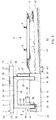
- Platform 1 serves as a platform for conveniently entering one on tracks 2 stopping train.
- the top 3 of the platform 1 is therefore opposite Level 4 of the ballast bed 5 and the rails 6 increased by, for example, 50 to 100 cm. This is achieved by a platform plate 7 serving as the upper edge of the platform a supporting structure 8 is supported at the desired height.
- FIG. 2 in the construction according to FIG Outside platform platform 1 designed several platform plates 7, which in Longitudinal direction of the platform 1 or the tracks 2 are arranged one behind the other.
- the supporting structure 8 supports the platform plates 7 in each case in the region of the butt joint 9 between two adjacent platform plates 7.
- each butt joint 9 and in the area of the outer end faces of the A two-part support element 10 is provided for the two outermost platform plates 7.
- This prefabricated foundation component 12 can have an approximately square vertical section with a width and a height from about 60 to 80 cm.
- the length of the foundation component 12 corresponds approximately the width of the platform 1, but can in the case of an overhanging Platform edge 13 may be somewhat shorter than the platform width, as can be seen in FIG. 1 results.
- This prefabricated foundation component 12 is placed on a cleanliness layer 14, which covers the ground 15 of the excavation 11 to a height of approximately 10 cm, placed so that a uniform weight transfer from the bottom 16 of the Precast foundation 12 is guaranteed in the soil 17.
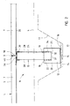
- the prefabricated foundation component 12 On its upper side 18, the prefabricated foundation component 12 has two identical, quiver-shaped recesses 19. These quiver recesses 19 are located on the vertical central plane of the prefabricated foundation component 12 and thus exactly in the center below the relevant butt joint 9 and are of the nearest End face 20 of the foundation component 12 spaced about 15 to 30 cm.
- the quiver recesses 19 have a rectangular or square Cross section that extends from the top 18 to the bottom 21 of the quiver recess is constant.
- the bottom 21 of the quiver recesses 19 is parallel to the underside 16 of the foundation component 12 and is about halfway up the same, while the side faces 22 of the quiver recesses 19 are perpendicular the bottom 16 run.
- the platform slabs 7 lie on the below the butt joint 9 and thus across the platform 1 extending central web 23 of a support member 24, the one has a bridge-like shape with two ends molded onto the central web 23 Support columns 25, which with their lower, free ends 26 in one of the two Quiver recesses 19 are used. Because the top 18 of the foundation component 12 runs parallel to its underside 16 and the two quiver recesses 19 the same depth and the two support columns 25 of the FT cross member 24 have identical lengths, the top 27 of the central web 23 is exact horizontal and can therefore be used directly for laying platform plates 7.
- the cross section of the support columns 25 corresponds approximately to the cross section of the quiver recesses 19, however, is slightly smaller than the latter, making it a jam-free one Inserting the FT cross member 24 into the quiver recesses 19 is guaranteed.
- the thickness of the central web 23 measured in the longitudinal direction of the platform 1 is correct preferably with the corresponding dimension of the support columns 25. So go the parallel to the butt joint 9 sides 28 of the support columns 25 without an edge into the relevant side surface 29 of the central web 23, so that the FT cross member 24 can be concreted on a conventional vibrating table. In the area of transition from the support columns 25 to the central part 23 tendon-like reinforcements 30 provide increased stability of the FT cross member 24.
- the distance between the two flat sides 28 of the FT cross member 24 can be between 20 and 40 cm, preferably about 30 cm, while the thickness of a support column measured in the longitudinal direction of the butt joint 9 25 can be between 15 and 40 cm, preferably about 20 cm.
- the material should be chosen so that under the weight of the load-bearing cross member 24 and the adjacent platform plates 7 only minimal deformation of the panes 31 occurs, so that surface irregularities are compensated and thereby full-surface contact between the underside of the column 32 and the recess base 21 is guaranteed.
- the bearing disks 31 can have an area be adapted approximately to the cross section of the quiver recesses 19.
- wedges or plates 34 used to the support columns 25 and thus the entire FT cross member 24 exactly to be able to set up and stabilize vertically are also preferably made of a vibration-damping material, for example hard rubber.
- the invention recommends the Use of unreinforced neoprene strips.
- the damping elements 31, 34, 36 become vibrations, such as those caused by passing trains, but also by Gusts of wind or the like can be triggered, damped, so that the load on the Support structure 8 and the placed platform plates 7 is mitigated.
- the transverse foundations 12 radially to the center of the subject Align the track arch so that its distance in the area of the track-side end faces 20 can be slightly smaller or larger than in the area of the outer end faces 20. This can be taken into account that in addition to the rectangular Platform plates 7 for straight track sections also platform plates 7 with a Trapezoidal shape are provided.
- the supporting structure 8 is predominantly based on the support of the static weight forces given the fact that the im Normal operation on the platform 1 side forces comparatively low are. Increased lateral forces are only for the exceptional case conceivable that a derailed rail vehicle abuts the platform edge 13. However, such a collision could also increase at most Force effects on platform 1 if one with higher speed moving train wagon derailed in the area of the platform Platform edge 13 for a force in the longitudinal direction of platform 1 none Starting point offers, could at best the cross-direction to the tracks 2 Force component on platform 1.
- the platform plates 7 according to the invention, as well as the parts 12, 24, are Support structure 8 made of a frost and de-icing resistant concrete, nevertheless care must also be taken to ensure that as little moisture as possible enters the Quiver recesses 19 penetrates, since the foundation component in strong frost 12 could burst open. This is due to the interaction of several Measures achieved: On the one hand, the height of the transverse foundations 12 is such dimensioned that their top 18 is not covered by soil, gravel or the like, so that no rainwater from the ballast bed 5 to the quiver recesses 19 can reach.
- Sloping rain is from the support structure 8 by means of the long sides of the platform 1 according to the invention arranged plates 37 kept away.
- the length of these positioning plates 37 corresponds to the length of the platform plate 7 under the base on the respective platform edge 13, 44, so that the end faces 47 of the positioning plates 37 aligned with the end faces 38 of the platform plates 7 in question.
- This allows the setting plates 37, on the one hand, each up to the center of the transverse foundation in question 12 placed on the same and just like the platform plates 7 to be strung together. This results in a continuous Platform edge, the vertical butt joints similar to the butt joint 9 can be sealed.
- the height of the setting plates 37 is slightly lower than that Distance between the bottom 35 of a platform plate 7 and the top 18 of the Cross foundations 12, so that in the area of the underside 35 of the platform plates 7 horizontally running gap of about 10 to 25 cm for cross ventilation of the Support structure 8 enclosed space remains.
- the setting plates 37 are Stabilization approached to the relevant support columns 25 of the FT cross member 24 and possibly screwed to the same, for example, via Halfen rails 48.
- the adjusting plates 37 serving as a side closure not to lean on the support columns 25 of the Ft cross member 24 from the outside, but instead to be placed below its central web 23 and then from the inside to the Support columns 25 move up.
- the adjusting plates 37 serving as a side closure not to lean on the support columns 25 of the Ft cross member 24 from the outside, but instead to be placed below its central web 23 and then from the inside to the Support columns 25 move up.
- the platform plate 7 is preferably placed on the supporting structure 8 in such a way that the track-side platform edge 13 to a greater extent over the supporting structure 8 protrudes as the outside platform edge 44 so that travelers comfortably in can get on a stopping train.
- the breadth of the Platform plates 7 between the two longitudinal edges 13, 44 by, for example, 50 to 100 cm larger than the relevant extension of the support structure 8.
- non-slip features are also used Knobs 49 incorporated, as well as one opposite the platform edge 13 set back guide strip 50.
- connection elements cast in the form Anchors, recesses or the like for fastening benches, information boards etc. are provided on the top 3 of the platform plates 7 .
- the platform plates 7 openings or Have recesses on which overhead line masts, roof racks etc., can be carried out, which in their own foundations between the Cross foundations 12 are anchored.
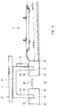
- the embodiment of the platform 61 from FIG. 3 differs from that previous only due to the different structure of the Foundation body 62, in contrast to the embodiment 1 according to the Figures 1 and 2, the quiver recesses 19 for the two free ends 26 of the Support columns 25 of the FT cross member 24 not in a common Foundation component, but arranged in two separate foundation bodies 62 are.
- the two foundation bodies 62 of a support element 10 can be approximately the same Have cross-section like the transverse foundation 12 of FIG. 1, while exclusively their extension in the direction of the butt joint 9 is considerably shortened, for example to one Extent from 80 cm to 120 cm, preferably about 100 cm.
- Fig. 4 it can be seen that in the simplest way, namely by putting them together two outer platforms 1, 61 with one-piece and / or divided transverse foundations 12, 62, a central platform 71 between two train tracks 2 can be created. There the top 3 slope of the platform slabs 7 to their now put together If the outer edges 44 are inclined, this can be done on the central platform 74 rainwater in the area of joint 72 between two side-by-side platform plates 7 are collected.
- a metal grate 73 through which the collected rainwater through to one above the Foundations 12, 62 running, preferably brick gutter 74 drips.
- the metal grate 73 in grooves 75 in the upper region of the rear platform edges 44 of platform plates 7 may be used.
- a drainage channel 76 preferably made of stainless steel, can be used. It can the gutter 76 has an approximately rectangular cross-section, its width is slightly less than the distance between the mutually facing edges 44 of the Platform plates 7. The channel 76 widens in its upper region 77 and can thereby positively hooked into the grooves 75, for example under Embedding in a mortar layer 78. The remaining gap between the peripheral Edge 79 of the drainage channel 76 and the grooves 75 can additionally sealed 80.
- a metal grate 81 can be placed on the gutter 76 be placed, the width of which is approximately the upper, enlarged region 77 of the Corridor gutter 76 corresponds, and its height approximately the height of this expanded Area 77 corresponds, so that the metal grate 81 approximately with the top 3 of the surrounding platform plates 7 completes.
Landscapes
- Engineering & Computer Science (AREA)
- Architecture (AREA)
- Civil Engineering (AREA)
- Structural Engineering (AREA)
- Bridges Or Land Bridges (AREA)
- Ladders (AREA)
- Auxiliary Methods And Devices For Loading And Unloading (AREA)
Applications Claiming Priority (2)
| Application Number | Priority Date | Filing Date | Title |
|---|---|---|---|
| DE19959236A DE19959236C1 (de) | 1999-09-10 | 1999-12-08 | Bahnsteig |
| DE19959236 | 1999-12-08 |
Publications (2)
| Publication Number | Publication Date |
|---|---|
| EP1106737A2 true EP1106737A2 (fr) | 2001-06-13 |
| EP1106737A3 EP1106737A3 (fr) | 2003-08-20 |
Family
ID=7931898
Family Applications (1)
| Application Number | Title | Priority Date | Filing Date |
|---|---|---|---|
| EP00122625A Withdrawn EP1106737A3 (fr) | 1999-12-08 | 2000-11-01 | Quai |
Country Status (1)
| Country | Link |
|---|---|
| EP (1) | EP1106737A3 (fr) |
Cited By (7)
| Publication number | Priority date | Publication date | Assignee | Title |
|---|---|---|---|---|
| CN104562919A (zh) * | 2015-01-08 | 2015-04-29 | 中铁十五局集团有限公司 | 一种站线分离的高架站结构 |
| CN106917355A (zh) * | 2017-03-10 | 2017-07-04 | 中建隧道建设有限公司 | 一种轨道梁体的施工方法 |
| CN107939074A (zh) * | 2017-11-27 | 2018-04-20 | 广州地铁设计研究院有限公司 | 一种预制拼装式的地铁车站站台及其施工方法 |
| CN111119521A (zh) * | 2020-01-08 | 2020-05-08 | 中铁二十三局集团有限公司 | 一种地铁车站的预制站台板及其吊运安装方法 |
| CN111501586A (zh) * | 2020-04-14 | 2020-08-07 | 中铁第四勘察设计院集团有限公司 | 一种装配式站台 |
| CN114875959A (zh) * | 2021-12-01 | 2022-08-09 | 广州华隧威预制件有限公司 | 拼装式地铁站台及其施工方法 |
| CN115123312A (zh) * | 2022-06-02 | 2022-09-30 | 广州地铁设计研究院股份有限公司 | 一种地铁车站预制式站台结构 |
Citations (1)
| Publication number | Priority date | Publication date | Assignee | Title |
|---|---|---|---|---|
| DE4316203A1 (de) | 1992-05-20 | 1993-11-25 | Stewing Beton & Fertigteilwerk | Bausatz zum Erstellen eines Bahnsteiges in Fertigteilbauweise |
Family Cites Families (3)
| Publication number | Priority date | Publication date | Assignee | Title |
|---|---|---|---|---|
| BE1001360A3 (fr) * | 1988-01-20 | 1989-10-10 | Const Et Entpr S Ind S A | Pont semi-prefabrique. |
| DE3826096A1 (de) * | 1988-08-01 | 1990-02-15 | Frenzel Otto Bauunternehmen | Bausatz fuer bahnsteig |
| DE4431470A1 (de) * | 1994-09-03 | 1996-03-07 | Mannheimer Verkehrs Ag Mvg | Bahnsteig für eine Haltestelle für Personenbeförderungsfahrzeuge |
-
2000
- 2000-11-01 EP EP00122625A patent/EP1106737A3/fr not_active Withdrawn
Patent Citations (1)
| Publication number | Priority date | Publication date | Assignee | Title |
|---|---|---|---|---|
| DE4316203A1 (de) | 1992-05-20 | 1993-11-25 | Stewing Beton & Fertigteilwerk | Bausatz zum Erstellen eines Bahnsteiges in Fertigteilbauweise |
Cited By (8)
| Publication number | Priority date | Publication date | Assignee | Title |
|---|---|---|---|---|
| CN104562919A (zh) * | 2015-01-08 | 2015-04-29 | 中铁十五局集团有限公司 | 一种站线分离的高架站结构 |
| CN106917355A (zh) * | 2017-03-10 | 2017-07-04 | 中建隧道建设有限公司 | 一种轨道梁体的施工方法 |
| CN106917355B (zh) * | 2017-03-10 | 2019-06-04 | 中建隧道建设有限公司 | 一种轨道梁体的施工方法 |
| CN107939074A (zh) * | 2017-11-27 | 2018-04-20 | 广州地铁设计研究院有限公司 | 一种预制拼装式的地铁车站站台及其施工方法 |
| CN111119521A (zh) * | 2020-01-08 | 2020-05-08 | 中铁二十三局集团有限公司 | 一种地铁车站的预制站台板及其吊运安装方法 |
| CN111501586A (zh) * | 2020-04-14 | 2020-08-07 | 中铁第四勘察设计院集团有限公司 | 一种装配式站台 |
| CN114875959A (zh) * | 2021-12-01 | 2022-08-09 | 广州华隧威预制件有限公司 | 拼装式地铁站台及其施工方法 |
| CN115123312A (zh) * | 2022-06-02 | 2022-09-30 | 广州地铁设计研究院股份有限公司 | 一种地铁车站预制式站台结构 |
Also Published As
| Publication number | Publication date |
|---|---|
| EP1106737A3 (fr) | 2003-08-20 |
Similar Documents
| Publication | Publication Date | Title |
|---|---|---|
| EP3521557B1 (fr) | Cadre multifonction pour constructions tubulaires | |
| EP0865540B1 (fr) | Ensemble de construction pour quai de gare modulaire | |
| AT391499B (de) | Eisenbahnoberbau, insbesondere fuer schienenfahrzeuge mit sehr hohen fahrgeschwindigkeiten | |
| DE19503220A1 (de) | System für den schotterlosen Oberbau von Gleisanlagen | |
| EP0357161B1 (fr) | Quai ferroviaire | |
| DE3826096A1 (de) | Bausatz fuer bahnsteig | |
| AT505789B1 (de) | Gleiskörper mit geklebten trögen | |
| DE19620731A1 (de) | Feste Fahrbahn für schienengebundene Fahrzeuge auf Brücken und Verfahren zu ihrer Herstellung | |
| DE10009506A1 (de) | Betonlose Schwelle | |
| EP1106737A2 (fr) | Quai | |
| DE19959236C1 (de) | Bahnsteig | |
| DE19849266C2 (de) | Feste Fahrbahn für eine Straßenbahn | |
| DE4430769C2 (de) | Eisenbahnoberbau mit einem auf einer durchgehenden Tragplatte aus Stahlbeton aufgelagerten Gleisrost | |
| EP0546380B1 (fr) | Structure de voie ferrée | |
| DE19741059C1 (de) | Verfahren zur Herstellung einer Festen Fahrbahn für schienengebundenen Verkehr, sowie eine Feste Fahrbahn zur Durchführung des Verfahrens | |
| EP1426495A2 (fr) | Méthode et dispositif pour construire un tunnel ou une tranchée | |
| EP0905319A2 (fr) | Voie ferrée et sa méthode de réalisation | |
| WO2003104562A1 (fr) | Element beton prefabrique et procede | |
| EP2166149B1 (fr) | Unité de pièce de structure de voie ferrée | |
| EP0456147A1 (fr) | Structure de voie ferrée | |
| DE3203980C2 (de) | Unterführungsbauwerk sowie Verfahren zu seiner Herstellung | |
| DE69916641T2 (de) | Verbesserungen an oder in bezug auf bahnanlagen für schienenfahrzeuge | |
| DE102017131351A1 (de) | Trogförmiger Überbau für eine Brücke, Brücke, Fertigteil für eine Trogwange einer Brücke sowie Verfahren zur Herstellung einer Brücke | |
| DE19837950A1 (de) | Verfahren zur Herstellung einer Festen Fahrbahn für schienengebundenen Verkehr und Vorrichtung zur Durchführung des Verfahrens | |
| DE19854246A1 (de) | Verfahren und System zum Bau und Umbau von Bahnsteigen mit veränderbaren Höhen |
Legal Events
| Date | Code | Title | Description |
|---|---|---|---|
| PUAI | Public reference made under article 153(3) epc to a published international application that has entered the european phase |
Free format text: ORIGINAL CODE: 0009012 |
|
| AK | Designated contracting states |
Kind code of ref document: A2 Designated state(s): AT BE CH CY DE DK ES FI FR GB GR IE IT LI LU MC NL PT SE TR |
|
| AX | Request for extension of the european patent |
Free format text: AL;LT;LV;MK;RO;SI |
|
| PUAL | Search report despatched |
Free format text: ORIGINAL CODE: 0009013 |
|
| AK | Designated contracting states |
Designated state(s): AT BE CH CY DE DK ES FI FR GB GR IE IT LI LU MC NL PT SE TR |
|
| AX | Request for extension of the european patent |
Extension state: AL LT LV MK RO SI |
|
| RIC1 | Information provided on ipc code assigned before grant |
Ipc: 7E 02D 27/32 B Ipc: 7E 01F 1/00 A |
|
| AKX | Designation fees paid | ||
| REG | Reference to a national code |
Ref country code: DE Ref legal event code: 8566 |
|
| STAA | Information on the status of an ep patent application or granted ep patent |
Free format text: STATUS: THE APPLICATION IS DEEMED TO BE WITHDRAWN |
|
| 18D | Application deemed to be withdrawn |
Effective date: 20040221 |