EP1106448A2 - Fahrzeugseitenblech mit aufprallweicher Aussenkante - Google Patents
Fahrzeugseitenblech mit aufprallweicher Aussenkante Download PDFInfo
- Publication number
- EP1106448A2 EP1106448A2 EP00124266A EP00124266A EP1106448A2 EP 1106448 A2 EP1106448 A2 EP 1106448A2 EP 00124266 A EP00124266 A EP 00124266A EP 00124266 A EP00124266 A EP 00124266A EP 1106448 A2 EP1106448 A2 EP 1106448A2
- Authority
- EP
- European Patent Office
- Prior art keywords
- outer edge
- side panel
- section
- fastening
- vehicle
- Prior art date
- Legal status (The legal status is an assumption and is not a legal conclusion. Google has not performed a legal analysis and makes no representation as to the accuracy of the status listed.)
- Granted
Links
Images
Classifications
-
- B—PERFORMING OPERATIONS; TRANSPORTING
- B60—VEHICLES IN GENERAL
- B60R—VEHICLES, VEHICLE FITTINGS, OR VEHICLE PARTS, NOT OTHERWISE PROVIDED FOR
- B60R21/00—Arrangements or fittings on vehicles for protecting or preventing injuries to occupants or pedestrians in case of accidents or other traffic risks
- B60R21/34—Protecting non-occupants of a vehicle, e.g. pedestrians
- B60R2021/343—Protecting non-occupants of a vehicle, e.g. pedestrians using deformable body panel, bodywork or components
Definitions
- the invention relates to a vehicle side panel with an impact-soft outer edge, comprising an outer trim section for a vehicle body and one molded inward along an outer edge thereof and bent inward Fastening section, the one immediately adjacent to the outer edge Deformation area with two substantially parallel to the outer edge has longitudinal beads bent opposite to each other, as well as several, fastening tabs angled in relation to the deformation area for coupling of the side panel to the vehicle body.
- Such side panels are used, for example, as fenders in motor vehicles used in the event of a collision of the motor vehicle with a person Reduce the risk of injury.
- DE 30 47 969 A1 describes a vehicle side panel of the type mentioned at the outset known that is attached to a vehicle body as a fender.
- Vehicle side panel closes down on the outer edge, i.e. in relation to the Vehicle body to the vehicle floor angled fastening section, which directly adjacent to the outer edge has a deformation area in the form of has two longitudinal beads bent opposite to each other, which are extend continuously along the outer edge.
- deformation area connect several, spaced apart, profiled fastening tabs over which is connected to a vertical body section. The latter is involved in this a depression extending laterally outwards into the fender, in which the respective fastening tabs engage substantially in conformity with the contour.
- the Fastening takes place via screws that run essentially horizontally.
- This known mounting arrangement still has a relatively high Stiffness in the area of the outer edge of the side panel.
- a large height for the Attachment of the side plate a large height.
- the invention is based on the object, the risk of injury or the severity of the injuries in the event of a collision with a motor vehicle Reduce.
- each fastening tab is in itself with respect to the vehicle body substantially horizontally extending, flatter Fastening section designed to bear against the vehicle body, which to the Deformation area connects.
- This can be a for the mounting arrangement Realize particularly low overall height, without the high Deformation potential would be affected.
- the horizontal alignment allows of the fastening section to support the deformability, since a good one, especially in the event of an impact from above onto the outer edge Evasion behavior of the side panel to the outside is made possible.
- one Prevention of deformation caused by the body also allows easy assembly on the vehicle body, since the Attachment can easily be done from above, for example by means of screw bolts or if necessary also by welding.
- the deformation area includes further a third longitudinal bead between the fastening tabs on the one hand and the first two longitudinal beads on the other hand is arranged. So that can avoid the side panel can be further improved to the outside. With low impact forces then the deformation still moves in the elastic range, so that smaller ones Accidents on the side panels no permanent deformation occur.
- the third longitudinal bead is preferably on the outside edge corresponding to the first next longitudinal bead, bent.
- the recesses are arcuate formed, the apex of the arcuate recesses until short extend above the longitudinal bead that is closest to the outer edge.
- the arcuate recesses ending just above the longitudinal beads become a Interruption of the longitudinal beads and thus a desired weakening of the Stiffness achieved with regard to an outward deflection of the side plate.
- the side panel should not already deform when a person opposes it leans or relies on it. In such a case, the arcuate design the occurrence of voltage peaks avoided, which otherwise leads to a could cause unwanted buckling.
- a cover strip is provided, which on the Fixing tab is set and covers the recesses.
- the cover strip has a sealing lip which is above the apex of the Recesses elastic against the sheet metal section between the outer edge and the first longitudinal bead is present. This prevents water from flowing through the recesses in the vehicle can penetrate.
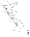
- the exemplary embodiment shows a vehicle side panel 1 in the form of a front left Fender of a passenger car.
- this shows Vehicle side panel 1 on an outer panel section 2, which is a part the outer skin of a vehicle.
- the trim section 2 is towards the inside of the Vehicle body bent over, the apex line of the bend a Outer edge 3 shown.
- the attachment to the vehicle body section 13 takes place via a plurality of fastening tabs formed on the fastening section 5.
- Deformation area 4 is provided, which deforms in the event of a collision with a person, see above that overall an impact-soft outer edge 3 is formed.
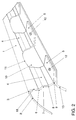
- the fastening tabs 5 are each in the form of formed substantially horizontally extending, flat sheet metal sections that on stand up a horizontal support portion 13 of the vehicle body.
- the Connection to the carrier section 13 takes place in the illustrated embodiment by fastening bolts 12, which from above by corresponding to the Fastening tab 5 provided through openings and with the Carrier section 13 of the body are clamped.
- the Support section 13 reinforced with weld nuts.
- you can other fastening means known for joining metal sheets are also used become. It is also possible to close the fastening tabs 5 with the carrier section 13 weld.
- the deformation areas 4 have aligned longitudinal beads, which in the run essentially parallel to the outer edge 3.
- a first sheet section 18 extends from the inwardly bent outer edge 3 to a first Longitudinal bead 6 essentially vertically downwards.
- the bend in the first longitudinal bead 6 is opposite to that of the outer edge 3, so that at the first Sheet metal section a second, inclined downwards towards the vehicle longitudinal center axis Sheet metal section is formed, which extends to a second longitudinal bead 7.
- Their Bend is opposite to that of the first longitudinal bead 6, so that after the sheet metal section adjoining the longitudinal bead 7 at the bottom again runs steeper until one third longitudinal bead 8 is reached.
- Their bend is in the same direction as the one on the first longitudinal bead 6.
- the down on the longitudinal bead 8 subsequent sheet metal section then extends outward to one directed bend 9 on which the corresponding mounting tab 5 to the Deformation area 4 adjoins.
- the sheet metal section between the first and second longitudinal beads 6 and 7 and the sheet metal section between the third Longitudinal bead 8 and the bend 9 of a mounting tab 5 essentially arranged parallel to each other. Furthermore, these sheet metal sections are related to the vehicle body inclined relative to a vertical such that the profile width of the side panel 1 between the trim section 2 and the Fastening section 4 viewed from the outer edge 3, d. H. here after increases below.
- each in the Deformation region 4 extend and interrupt the longitudinal beads 6, 7, 8.
- the Recesses 10 are arcuate, the apex 11 of the Arch each up to just above the first longitudinal bead 6, d. H. the longitudinal bead, which is closest to the outer edge 3.
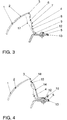
- Longitudinal beads 6, 7, 8 result in a large one for the deformation regions 4 Deformation capacity, so that in the event of a person colliding with the outer edge 3 the side panel 1 can move outwards, thereby increasing the risk of injury or the severity of an injury to the person can be reduced.
- the Evasion behavior is shown in Figure 3 using the phantom line 17, the position represents an inner wall of a deformation region 4 in the event of an impact.
- Out Figure 3 can be seen in particular that the deformability of the Deformation area 4 through the carrier portion 13 of the body is affected.
- the outer edge 3 remains sufficiently rigid to prevent this from occurring at a substantially static Load, for example when a person leans against the side panel 1 or relies on this, is not permanently deformed. Due to the arched design In such a case, the recess 10 becomes voltage peaks which cause a buckling avoided.
- the cover strip 14 On the fastening section of the side plate 1 there is also a cover strip 14 provided, which is fixed to the mounting tab 5 and the recesses 10 covers.
- the cover strip 14 can be designed, for example, as a water drainage channel become.
- the cover strip 14 for this includes a Fastening tab 5 and the associated fasteners 12 covering Base section 16, from which an elastic flange section is straight in the direction the outer edge 3 extends.
- the flange section is at one end with a provided continuous sealing lip 15 which against the first sheet metal section 18th above the apex 11 of the recesses 10 in the longitudinal direction of the outer edge 3 sealingly rests against it due to the elasticity of the flange section Pressure is biased.
- the cover strip 14 is preferably made of plastic.
Landscapes
- Engineering & Computer Science (AREA)
- Mechanical Engineering (AREA)
- Body Structure For Vehicles (AREA)
- Vehicle Interior And Exterior Ornaments, Soundproofing, And Insulation (AREA)
Abstract
Description
- Figur 1
- ein Fahrzeugseitenblech in Form eines linken, vorderen Kotflügels eines Kraftfahrzeuges in räumlicher Darstellung,
- Figur 2
- eine vergrößerte Darstellung der Außenkante und des Befestigungsabschnittes des Fahrzeugseitenbleches von Figur 1,
- Figur 3
- einen Schnitt durch die Außenkante und den Befestigungsabschnitt im Bereich eines Befestigungslappens, und in
- Figur 4
- einen Schnitt entsprechend Figur 3, bei dem zusätzlich eine Abdeckleiste mit dargestellt ist.
- 1
- Seitenblech
- 2
- Verkleidungsabschnitt
- 3
- Außenkante
- 4
- Deformationsbereich
- 5
- Befestigungslappen
- 6
- erste Längssicke
- 7
- zweite Längssicke
- 8
- dritte Längssicke
- 9
- Abwinkelung
- 10
- Ausnehmung
- 11
- Scheitel der Ausnehmung
- 12
- Befestigungsbolzen
- 13
- Trägerabschnitt der Karosserie
- 14
- Abdeckleiste
- 15
- Dichtlippe der Abdeckleiste
- 16
- Sockelabschnitt der Abdeckleiste
- 17
- Phantomlinie der Innenwand des Deformationsbereiches
- 18
- erster Blechabschnitt
Claims (9)
- Fahrzeugseitenblech mit aufprallweicher Außenkante, umfassend einen außenliegenden Verkleidungsabschnitt (2) für eine Fahrzeugkarosserie und einen entlang einer Außenkante (3) an diesen angeformten, nach innen umgebogenen Befestigungsabschnitt, der einen an die Außenkante (3) unmittelbar anschließenden Deformationsbereich (4) mit zwei im wesentlichen parallel zu der Außenkante (3) verlaufenden, entgegengesetzt zueinander gebogenen Längssicken (6, 7) aufweist, sowie mehrere, gegenüber dem Deformationsbereich (4) abgewinkelte Befestigungslappen (5) zur Ankopplung des Seitenbleches (1) an die Fahrzeugkarosserie, dadurch gekennzeichnet, daß zwischen den Befestigungslappen (5) gebildete Ausnehmungen (10) sich jeweils bis in den Deformationsbereich (4) erstrecken und die Längssicken (6, 7) unterbrechen.
- Fahrzeugseitenblech nach Anspruch 1, dadurch gekennzeichnet, daß jeder Befestigungslappen (5) als sich in bezug auf die Fahrzeugkarosserie im wesentlichen horizontal erstreckender, flacher Blechabschnitt zur Anlage gegen die Fahrzeugkarosserie ausgebildet ist, der an den Deformationsbereich (4) anschließt.
- Fahrzeugseitenblech nach Anspruch 1 oder 2, dadurch gekennzeichnet, daß der Deformationsbereich (4) weiterhin eine dritte Längssicke (8) umfaßt, die zwischen den Befestigungslappen (5) einerseits und den ersten beiden Längssicken (6, 7) andererseits angeordnet ist.
- Fahrzeugseitenblech nach Anspruch 3, dadurch gekennzeichnet, daß die dritte Längssicke (8) entsprechend der ersten, der Außenkante (3) am nächsten liegenden Längssicke (6), gebogen ist.
- Fahrzeugseitenblech nach einem der Ansprüche 1 bis 4, dadurch gekennzeichnet, daß ein Blechabschnitt zwischen der ersten und der zweiten Längssicke (6, 7) und ein Blechabschnitt zwischen der dritten Längssicke (8) und der Abwinkelung (9) eines Befestigungslappens (5) im wesentlichen parallel zueinander angeordnet sind und in bezug auf die Fahrzeugkarosserie gegenüber einer Vertikalen derart geneigt sind, daß die Profilweite des Seitenbleches (1) zwischen dem Verkleidungsabschnitt (2) und dem Befestigungsabschnitt von der Außenkante (3) ausgehend betrachtet zunimmt.
- Fahrzeugseitenblech nach einem der Ansprüche 1 bis 5, dadurch gekennzeichnet, daß die Ausnehmungen (10) bogenförmig ausgebildet sind, wobei sich die Scheitel (11) der bogenförmigen Ausnehmungen (10) um bis kurz oberhalb derjenigen Längssicke (6) erstrecken, welche der Außenkante (3) am nächsten liegt.
- Fahrzeugseitenblech nach einem der Ansprüche 1 bis 6, dadurch gekennzeichnet, daß entlang des Befestigungsabschnittes eine Abdeckleiste (14) vorgesehen ist, welche an den Befestigungslappen (5) festgelegt ist und die Ausnehmungen (10) abdeckt.
- Fahrzeugseitenblech nach Anspruch 7, dadurch gekennzeichnet, daß die Abdeckleiste (14) eine Dichtlippe (15) aufweist, die oberhalb der Scheitel (11) der Ausnehmungen (10) elastisch gegen den Blechabschnitt (18) zwischen der Außenkante (3) und der ersten Längssicke (6) anliegt.
- Kraftfahrzeug, dessen vordere Kotflügel jeweils durch ein Fahrzeugseitenblech (1) nach einem der Ansprüche 1 bis 8 gebildet sind.
Applications Claiming Priority (2)
| Application Number | Priority Date | Filing Date | Title |
|---|---|---|---|
| DE19959606 | 1999-12-10 | ||
| DE19959606A DE19959606A1 (de) | 1999-12-10 | 1999-12-10 | Fahrzeugseitenblech mit aufprallweicher Außenkante |
Publications (3)
| Publication Number | Publication Date |
|---|---|
| EP1106448A2 true EP1106448A2 (de) | 2001-06-13 |
| EP1106448A3 EP1106448A3 (de) | 2004-01-14 |
| EP1106448B1 EP1106448B1 (de) | 2006-03-01 |
Family
ID=7932160
Family Applications (1)
| Application Number | Title | Priority Date | Filing Date |
|---|---|---|---|
| EP00124266A Expired - Lifetime EP1106448B1 (de) | 1999-12-10 | 2000-11-13 | Fahrzeugseitenblech mit aufprallweicher Aussenkante |
Country Status (3)
| Country | Link |
|---|---|
| EP (1) | EP1106448B1 (de) |
| AT (1) | ATE318736T1 (de) |
| DE (2) | DE19959606A1 (de) |
Cited By (4)
| Publication number | Priority date | Publication date | Assignee | Title |
|---|---|---|---|---|
| FR2860763A1 (fr) * | 2003-10-13 | 2005-04-15 | Renault Sa | Element de carrosserie pre-amenager pour amortir un choc pieton |
| EP1574423A1 (de) * | 2004-03-09 | 2005-09-14 | GM Global Technology Operations, Inc. | Vorderbau für ein Kraftfahrzeug |
| EP2008884A1 (de) * | 2007-06-28 | 2008-12-31 | Ford Global Technologies, LLC | Motorhaube für Kraftfahrzeuge |
| WO2020254747A1 (fr) * | 2019-06-21 | 2020-12-24 | Psa Automobiles Sa | Aile de vehicule avec zone fusible pour deformation programmee |
Families Citing this family (9)
| Publication number | Priority date | Publication date | Assignee | Title |
|---|---|---|---|---|
| DE10244455A1 (de) | 2002-09-24 | 2004-05-13 | Volkswagen Ag | Kotflügelaufbau an Kraftfahrzeugen |
| DE10317178B3 (de) * | 2003-04-15 | 2004-10-21 | Benteler Automobiltechnik Gmbh | Kraftfahrzeug |
| DE102004048504A1 (de) | 2004-10-05 | 2006-04-13 | Rehau Ag + Co | Karosserieelement sowie Absorberkörper für ein Karosserieelement |
| DE102006015400B4 (de) * | 2006-04-03 | 2010-05-20 | Audi Ag | Karosseriebauteil für einen Kraftwagen |
| DE102010016213A1 (de) * | 2010-03-30 | 2011-10-06 | Dr. Ing. H.C. F. Porsche Aktiengesellschaft | Kraftfahrzeug |
| DE102020111049B4 (de) | 2020-04-23 | 2022-03-17 | Dr. Ing. H.C. F. Porsche Aktiengesellschaft | Kotflügelanordnung für ein Kraftfahrzeug |
| DE102020113606B4 (de) | 2020-05-20 | 2023-03-30 | PRINZ Kinematics GmbH | Fronthaubenscharnier und Fronthaubenscharnierkonstruktion |
| DE102020118919A1 (de) | 2020-07-17 | 2022-01-20 | Dr. Ing. H.C. F. Porsche Aktiengesellschaft | Anordnung zur seitlichen Abdeckung eines inneren Bereichs einer Vorderwagenstruktur eines Kraftfahrzeugs |
| DE102020121813A1 (de) | 2020-08-20 | 2022-02-24 | Audi Aktiengesellschaft | Kotflügelhalter |
Citations (1)
| Publication number | Priority date | Publication date | Assignee | Title |
|---|---|---|---|---|
| DE3047969A1 (de) | 1979-08-23 | 1982-07-22 | Daimler-Benz Ag, 7000 Stuttgart | Kraftfahrzeug, insbesondere personenkraftwagen |
Family Cites Families (4)
| Publication number | Priority date | Publication date | Assignee | Title |
|---|---|---|---|---|
| DE2934060A1 (de) * | 1979-08-23 | 1981-03-26 | Daimler-Benz Aktiengesellschaft, 70567 Stuttgart | Kraftfahrzeug, insbesondere personenkraftwagen, mit nachgiebigen karosseriefrontteilen |
| EP0561826B1 (de) * | 1990-12-20 | 1994-08-10 | Audi Ag | Fahrzeugkarosserie für einen personenkrafwagen |
| DE4401023C1 (de) * | 1994-01-15 | 1995-03-16 | Daimler Benz Ag | Kraftfahrzeugvorbau |
| JPH11222154A (ja) * | 1998-02-04 | 1999-08-17 | Toyota Motor Corp | 自動車のフェンダー構造 |
-
1999
- 1999-12-10 DE DE19959606A patent/DE19959606A1/de not_active Withdrawn
-
2000
- 2000-11-13 EP EP00124266A patent/EP1106448B1/de not_active Expired - Lifetime
- 2000-11-13 DE DE50012294T patent/DE50012294D1/de not_active Expired - Lifetime
- 2000-11-13 AT AT00124266T patent/ATE318736T1/de not_active IP Right Cessation
Patent Citations (1)
| Publication number | Priority date | Publication date | Assignee | Title |
|---|---|---|---|---|
| DE3047969A1 (de) | 1979-08-23 | 1982-07-22 | Daimler-Benz Ag, 7000 Stuttgart | Kraftfahrzeug, insbesondere personenkraftwagen |
Cited By (6)
| Publication number | Priority date | Publication date | Assignee | Title |
|---|---|---|---|---|
| FR2860763A1 (fr) * | 2003-10-13 | 2005-04-15 | Renault Sa | Element de carrosserie pre-amenager pour amortir un choc pieton |
| WO2005035325A1 (fr) * | 2003-10-13 | 2005-04-21 | Renault S.A.S | Element de carrosserie pre-amenage pour amortir un choc pieton |
| EP1574423A1 (de) * | 2004-03-09 | 2005-09-14 | GM Global Technology Operations, Inc. | Vorderbau für ein Kraftfahrzeug |
| EP2008884A1 (de) * | 2007-06-28 | 2008-12-31 | Ford Global Technologies, LLC | Motorhaube für Kraftfahrzeuge |
| WO2020254747A1 (fr) * | 2019-06-21 | 2020-12-24 | Psa Automobiles Sa | Aile de vehicule avec zone fusible pour deformation programmee |
| FR3097494A1 (fr) * | 2019-06-21 | 2020-12-25 | Psa Automobiles Sa | Aile de vehicule avec zone fusible pour deformation programmee |
Also Published As
| Publication number | Publication date |
|---|---|
| EP1106448A3 (de) | 2004-01-14 |
| DE50012294D1 (de) | 2006-04-27 |
| DE19959606A1 (de) | 2001-06-13 |
| EP1106448B1 (de) | 2006-03-01 |
| ATE318736T1 (de) | 2006-03-15 |
Similar Documents
| Publication | Publication Date | Title |
|---|---|---|
| EP1132263B1 (de) | Kotflügelanordnung für ein Kraftfahrzeug | |
| EP0992418B1 (de) | Karosseriehaube, insbesondere Motorraumhaube eines Kraftfahrzeugs | |
| EP1106448B1 (de) | Fahrzeugseitenblech mit aufprallweicher Aussenkante | |
| DE102017123325A1 (de) | Stoßfängerquerträger | |
| WO2018162284A1 (de) | Scharnieranordnung für eine frontklappe eines kraftfahrzeugs und kraftfahrzeug | |
| EP3022086B1 (de) | Rückenlehnenstruktur für einen fahrzeugsitz und fahrzeugsitz | |
| DE10102187A1 (de) | Aufpralldämpfender Kotflügel für ein Fahrzeug | |
| EP1262397B1 (de) | Fronthaubenanordnung für einen Personenkraftwagen | |
| EP1129928B1 (de) | Kotflügelanordnung für ein Kraftfahrzeug | |
| EP1090818B1 (de) | Fussgängerfreundlich ausgelegtes Kraftfahrzeug-Frontend | |
| DE102020104097A1 (de) | Kraftfahrzeug-Stoßfänger | |
| DE102015102419A1 (de) | Stoßfängerabdeckungshalterung, Kühlergrill und Struktur eines Fahrzeugfrontabschnitts | |
| DE102008009964A1 (de) | Kollision-Detektorvorrichtung und Schutzsystem | |
| DE19706225C2 (de) | Kraftfahrzeug mit einer Abstützung zwischen Querträger und Spritzschutzwand | |
| EP1424233B1 (de) | Seitenaufprallträger | |
| DE102018211974A1 (de) | Stoßfängeranordnung und Füllelement | |
| DE202015001448U1 (de) | Fahrzeugsäule, insbesondere A-Säule für ein Kraftfahrzeug | |
| DE10317178B3 (de) | Kraftfahrzeug | |
| DE102019112913B4 (de) | Vorderwagen eines Kraftfahrzeugs | |
| DE60105747T2 (de) | Vorderwagenaufbau eines Fahrzeuges | |
| EP1457394B1 (de) | Personenkraftwagen | |
| DE102014009383B4 (de) | Struktur eines Fahrzeugkarosserie-Frontabschnitts | |
| DE10031372B4 (de) | Kotflügelanordnung für ein Kraftfahrzeug | |
| DE3301116A1 (de) | Verstelleinrichtung fuer fahrzeug-sitze | |
| EP1457393A1 (de) | Personenkraftwagen mit Fussgängerschutz |
Legal Events
| Date | Code | Title | Description |
|---|---|---|---|
| PUAI | Public reference made under article 153(3) epc to a published international application that has entered the european phase |
Free format text: ORIGINAL CODE: 0009012 |
|
| AK | Designated contracting states |
Kind code of ref document: A2 Designated state(s): AT BE CH CY DE DK ES FI FR GB GR IE IT LI LU MC NL PT SE TR |
|
| AX | Request for extension of the european patent |
Free format text: AL;LT;LV;MK;RO;SI |
|
| PUAL | Search report despatched |
Free format text: ORIGINAL CODE: 0009013 |
|
| AK | Designated contracting states |
Kind code of ref document: A3 Designated state(s): AT BE CH CY DE DK ES FI FR GB GR IE IT LI LU MC NL PT SE TR |
|
| AX | Request for extension of the european patent |
Extension state: AL LT LV MK RO SI |
|
| 17P | Request for examination filed |
Effective date: 20040714 |
|
| AKX | Designation fees paid |
Designated state(s): AT BE CH CY DE DK ES FI FR GB GR IE IT LI LU MC NL PT SE TR |
|
| GRAP | Despatch of communication of intention to grant a patent |
Free format text: ORIGINAL CODE: EPIDOSNIGR1 |
|
| GRAS | Grant fee paid |
Free format text: ORIGINAL CODE: EPIDOSNIGR3 |
|
| GRAA | (expected) grant |
Free format text: ORIGINAL CODE: 0009210 |
|
| AK | Designated contracting states |
Kind code of ref document: B1 Designated state(s): AT BE CH CY DE DK ES FI FR GB GR IE IT LI LU MC NL PT SE TR |
|
| PG25 | Lapsed in a contracting state [announced via postgrant information from national office to epo] |
Ref country code: IT Free format text: LAPSE BECAUSE OF FAILURE TO SUBMIT A TRANSLATION OF THE DESCRIPTION OR TO PAY THE FEE WITHIN THE PRE;WARNING: LAPSES OF ITALIAN PATENTS WITH EFFECTIVE DATE BEFORE 2007 MAY HAVE OCCURRED AT ANY TIME BEFORE 2007. THE CORRECT EFFECTIVE DATE MAY BE DIFFERENT FROM THE ONE RECORDED.SCRIBED TIME-LIMIT Effective date: 20060301 Ref country code: FI Free format text: LAPSE BECAUSE OF FAILURE TO SUBMIT A TRANSLATION OF THE DESCRIPTION OR TO PAY THE FEE WITHIN THE PRESCRIBED TIME-LIMIT Effective date: 20060301 Ref country code: IE Free format text: LAPSE BECAUSE OF FAILURE TO SUBMIT A TRANSLATION OF THE DESCRIPTION OR TO PAY THE FEE WITHIN THE PRESCRIBED TIME-LIMIT Effective date: 20060301 Ref country code: GB Free format text: LAPSE BECAUSE OF FAILURE TO SUBMIT A TRANSLATION OF THE DESCRIPTION OR TO PAY THE FEE WITHIN THE PRESCRIBED TIME-LIMIT Effective date: 20060301 Ref country code: NL Free format text: LAPSE BECAUSE OF FAILURE TO SUBMIT A TRANSLATION OF THE DESCRIPTION OR TO PAY THE FEE WITHIN THE PRESCRIBED TIME-LIMIT Effective date: 20060301 |
|
| REG | Reference to a national code |
Ref country code: GB Ref legal event code: FG4D Free format text: NOT ENGLISH |
|
| REG | Reference to a national code |
Ref country code: CH Ref legal event code: EP |
|
| REG | Reference to a national code |
Ref country code: IE Ref legal event code: FG4D Free format text: LANGUAGE OF EP DOCUMENT: GERMAN |
|
| REF | Corresponds to: |
Ref document number: 50012294 Country of ref document: DE Date of ref document: 20060427 Kind code of ref document: P |
|
| PG25 | Lapsed in a contracting state [announced via postgrant information from national office to epo] |
Ref country code: DK Free format text: LAPSE BECAUSE OF FAILURE TO SUBMIT A TRANSLATION OF THE DESCRIPTION OR TO PAY THE FEE WITHIN THE PRESCRIBED TIME-LIMIT Effective date: 20060601 Ref country code: SE Free format text: LAPSE BECAUSE OF FAILURE TO SUBMIT A TRANSLATION OF THE DESCRIPTION OR TO PAY THE FEE WITHIN THE PRESCRIBED TIME-LIMIT Effective date: 20060601 |
|
| PG25 | Lapsed in a contracting state [announced via postgrant information from national office to epo] |
Ref country code: ES Free format text: LAPSE BECAUSE OF FAILURE TO SUBMIT A TRANSLATION OF THE DESCRIPTION OR TO PAY THE FEE WITHIN THE PRESCRIBED TIME-LIMIT Effective date: 20060612 |
|
| PG25 | Lapsed in a contracting state [announced via postgrant information from national office to epo] |
Ref country code: PT Free format text: LAPSE BECAUSE OF FAILURE TO SUBMIT A TRANSLATION OF THE DESCRIPTION OR TO PAY THE FEE WITHIN THE PRESCRIBED TIME-LIMIT Effective date: 20060801 |
|
| NLV1 | Nl: lapsed or annulled due to failure to fulfill the requirements of art. 29p and 29m of the patents act | ||
| ET | Fr: translation filed | ||
| GBV | Gb: ep patent (uk) treated as always having been void in accordance with gb section 77(7)/1977 [no translation filed] |
Effective date: 20060301 |
|
| REG | Reference to a national code |
Ref country code: IE Ref legal event code: FD4D |
|
| PG25 | Lapsed in a contracting state [announced via postgrant information from national office to epo] |
Ref country code: MC Free format text: LAPSE BECAUSE OF NON-PAYMENT OF DUE FEES Effective date: 20061130 Ref country code: CH Free format text: LAPSE BECAUSE OF NON-PAYMENT OF DUE FEES Effective date: 20061130 Ref country code: LI Free format text: LAPSE BECAUSE OF NON-PAYMENT OF DUE FEES Effective date: 20061130 |
|
| PLBE | No opposition filed within time limit |
Free format text: ORIGINAL CODE: 0009261 |
|
| STAA | Information on the status of an ep patent application or granted ep patent |
Free format text: STATUS: NO OPPOSITION FILED WITHIN TIME LIMIT |
|
| 26N | No opposition filed |
Effective date: 20061204 |
|
| REG | Reference to a national code |
Ref country code: CH Ref legal event code: PL |
|
| PG25 | Lapsed in a contracting state [announced via postgrant information from national office to epo] |
Ref country code: AT Free format text: LAPSE BECAUSE OF NON-PAYMENT OF DUE FEES Effective date: 20061113 |
|
| PG25 | Lapsed in a contracting state [announced via postgrant information from national office to epo] |
Ref country code: GR Free format text: LAPSE BECAUSE OF FAILURE TO SUBMIT A TRANSLATION OF THE DESCRIPTION OR TO PAY THE FEE WITHIN THE PRESCRIBED TIME-LIMIT Effective date: 20060602 |
|
| PG25 | Lapsed in a contracting state [announced via postgrant information from national office to epo] |
Ref country code: TR Free format text: LAPSE BECAUSE OF FAILURE TO SUBMIT A TRANSLATION OF THE DESCRIPTION OR TO PAY THE FEE WITHIN THE PRESCRIBED TIME-LIMIT Effective date: 20060301 Ref country code: LU Free format text: LAPSE BECAUSE OF NON-PAYMENT OF DUE FEES Effective date: 20061113 |
|
| PG25 | Lapsed in a contracting state [announced via postgrant information from national office to epo] |
Ref country code: CY Free format text: LAPSE BECAUSE OF FAILURE TO SUBMIT A TRANSLATION OF THE DESCRIPTION OR TO PAY THE FEE WITHIN THE PRESCRIBED TIME-LIMIT Effective date: 20060301 |
|
| REG | Reference to a national code |
Ref country code: FR Ref legal event code: PLFP Year of fee payment: 16 |
|
| REG | Reference to a national code |
Ref country code: FR Ref legal event code: PLFP Year of fee payment: 17 |
|
| PGFP | Annual fee paid to national office [announced via postgrant information from national office to epo] |
Ref country code: DE Payment date: 20161130 Year of fee payment: 17 Ref country code: FR Payment date: 20161129 Year of fee payment: 17 |
|
| PGFP | Annual fee paid to national office [announced via postgrant information from national office to epo] |
Ref country code: BE Payment date: 20161125 Year of fee payment: 17 |
|
| REG | Reference to a national code |
Ref country code: DE Ref legal event code: R119 Ref document number: 50012294 Country of ref document: DE |
|
| REG | Reference to a national code |
Ref country code: FR Ref legal event code: ST Effective date: 20180731 Ref country code: BE Ref legal event code: MM Effective date: 20171130 |
|
| PG25 | Lapsed in a contracting state [announced via postgrant information from national office to epo] |
Ref country code: DE Free format text: LAPSE BECAUSE OF NON-PAYMENT OF DUE FEES Effective date: 20180602 Ref country code: FR Free format text: LAPSE BECAUSE OF NON-PAYMENT OF DUE FEES Effective date: 20171130 |
|
| PG25 | Lapsed in a contracting state [announced via postgrant information from national office to epo] |
Ref country code: BE Free format text: LAPSE BECAUSE OF NON-PAYMENT OF DUE FEES Effective date: 20171130 |