EP1105243B1 - Turbine rotor modernization and repair method - Google Patents
Turbine rotor modernization and repair method Download PDFInfo
- Publication number
- EP1105243B1 EP1105243B1 EP99942328A EP99942328A EP1105243B1 EP 1105243 B1 EP1105243 B1 EP 1105243B1 EP 99942328 A EP99942328 A EP 99942328A EP 99942328 A EP99942328 A EP 99942328A EP 1105243 B1 EP1105243 B1 EP 1105243B1
- Authority
- EP
- European Patent Office
- Prior art keywords
- weld
- welding
- volumes
- spaced apart
- metal
- Prior art date
- Legal status (The legal status is an assumption and is not a legal conclusion. Google has not performed a legal analysis and makes no representation as to the accuracy of the status listed.)
- Expired - Lifetime
Links
- 238000000034 method Methods 0.000 title claims description 75
- 230000008439 repair process Effects 0.000 title description 45
- 238000003466 welding Methods 0.000 claims description 60
- 239000002184 metal Substances 0.000 claims description 43
- 229910052751 metal Inorganic materials 0.000 claims description 43
- 239000011324 bead Substances 0.000 claims description 36
- 238000000151 deposition Methods 0.000 claims description 27
- 239000000945 filler Substances 0.000 claims description 21
- WFKWXMTUELFFGS-UHFFFAOYSA-N tungsten Chemical compound [W] WFKWXMTUELFFGS-UHFFFAOYSA-N 0.000 claims description 7
- 229910052721 tungsten Inorganic materials 0.000 claims description 7
- 239000010937 tungsten Substances 0.000 claims description 7
- 230000010355 oscillation Effects 0.000 claims description 5
- 238000000926 separation method Methods 0.000 claims description 2
- 241001016380 Reseda luteola Species 0.000 description 173
- 230000008569 process Effects 0.000 description 26
- 239000010410 layer Substances 0.000 description 18
- 239000010953 base metal Substances 0.000 description 10
- 230000008021 deposition Effects 0.000 description 10
- 239000000463 material Substances 0.000 description 8
- 238000005336 cracking Methods 0.000 description 6
- 238000003754 machining Methods 0.000 description 6
- 230000006872 improvement Effects 0.000 description 5
- 229910045601 alloy Inorganic materials 0.000 description 4
- 239000000956 alloy Substances 0.000 description 4
- 230000008901 benefit Effects 0.000 description 4
- 238000005242 forging Methods 0.000 description 4
- 230000015572 biosynthetic process Effects 0.000 description 3
- 230000007547 defect Effects 0.000 description 3
- 230000004907 flux Effects 0.000 description 3
- 238000010438 heat treatment Methods 0.000 description 3
- 239000002893 slag Substances 0.000 description 3
- 238000005496 tempering Methods 0.000 description 3
- 229910000831 Steel Inorganic materials 0.000 description 2
- 230000004927 fusion Effects 0.000 description 2
- 230000003993 interaction Effects 0.000 description 2
- 238000007885 magnetic separation Methods 0.000 description 2
- 239000010959 steel Substances 0.000 description 2
- 238000012360 testing method Methods 0.000 description 2
- 229910000851 Alloy steel Inorganic materials 0.000 description 1
- OKTJSMMVPCPJKN-UHFFFAOYSA-N Carbon Chemical compound [C] OKTJSMMVPCPJKN-UHFFFAOYSA-N 0.000 description 1
- CWYNVVGOOAEACU-UHFFFAOYSA-N Fe2+ Chemical compound [Fe+2] CWYNVVGOOAEACU-UHFFFAOYSA-N 0.000 description 1
- 229910000756 V alloy Inorganic materials 0.000 description 1
- 239000000729 antidote Substances 0.000 description 1
- 229910052799 carbon Inorganic materials 0.000 description 1
- 230000008859 change Effects 0.000 description 1
- 238000005253 cladding Methods 0.000 description 1
- 230000007797 corrosion Effects 0.000 description 1
- 238000005260 corrosion Methods 0.000 description 1
- 239000002537 cosmetic Substances 0.000 description 1
- 239000004744 fabric Substances 0.000 description 1
- 239000006249 magnetic particle Substances 0.000 description 1
- 238000004519 manufacturing process Methods 0.000 description 1
- 238000002844 melting Methods 0.000 description 1
- 230000008018 melting Effects 0.000 description 1
- 238000001465 metallisation Methods 0.000 description 1
- 230000004048 modification Effects 0.000 description 1
- 238000012986 modification Methods 0.000 description 1
- 229910052750 molybdenum Inorganic materials 0.000 description 1
- 238000009659 non-destructive testing Methods 0.000 description 1
- 238000010248 power generation Methods 0.000 description 1
- 238000002360 preparation method Methods 0.000 description 1
- 230000009467 reduction Effects 0.000 description 1
- 230000004044 response Effects 0.000 description 1
- 238000012163 sequencing technique Methods 0.000 description 1
- 239000002356 single layer Substances 0.000 description 1
- 238000010583 slow cooling Methods 0.000 description 1
- 239000007787 solid Substances 0.000 description 1
- 239000002904 solvent Substances 0.000 description 1
- 238000011282 treatment Methods 0.000 description 1
- 238000010792 warming Methods 0.000 description 1
- 239000002699 waste material Substances 0.000 description 1
Images
Classifications
-
- B—PERFORMING OPERATIONS; TRANSPORTING
- B23—MACHINE TOOLS; METAL-WORKING NOT OTHERWISE PROVIDED FOR
- B23P—METAL-WORKING NOT OTHERWISE PROVIDED FOR; COMBINED OPERATIONS; UNIVERSAL MACHINE TOOLS
- B23P6/00—Restoring or reconditioning objects
-
- B—PERFORMING OPERATIONS; TRANSPORTING
- B23—MACHINE TOOLS; METAL-WORKING NOT OTHERWISE PROVIDED FOR
- B23P—METAL-WORKING NOT OTHERWISE PROVIDED FOR; COMBINED OPERATIONS; UNIVERSAL MACHINE TOOLS
- B23P6/00—Restoring or reconditioning objects
- B23P6/002—Repairing turbine components, e.g. moving or stationary blades, rotors
- B23P6/007—Repairing turbine components, e.g. moving or stationary blades, rotors using only additive methods, e.g. build-up welding
-
- B—PERFORMING OPERATIONS; TRANSPORTING
- B23—MACHINE TOOLS; METAL-WORKING NOT OTHERWISE PROVIDED FOR
- B23K—SOLDERING OR UNSOLDERING; WELDING; CLADDING OR PLATING BY SOLDERING OR WELDING; CUTTING BY APPLYING HEAT LOCALLY, e.g. FLAME CUTTING; WORKING BY LASER BEAM
- B23K9/00—Arc welding or cutting
- B23K9/04—Welding for other purposes than joining, e.g. built-up welding
-
- B—PERFORMING OPERATIONS; TRANSPORTING
- B65—CONVEYING; PACKING; STORING; HANDLING THIN OR FILAMENTARY MATERIAL
- B65B—MACHINES, APPARATUS OR DEVICES FOR, OR METHODS OF, PACKAGING ARTICLES OR MATERIALS; UNPACKING
- B65B1/00—Packaging fluent solid material, e.g. powders, granular or loose fibrous material, loose masses of small articles, in individual containers or receptacles, e.g. bags, sacks, boxes, cartons, cans, or jars
- B65B1/04—Methods of, or means for, filling the material into the containers or receptacles
- B65B1/06—Methods of, or means for, filling the material into the containers or receptacles by gravity flow
-
- F—MECHANICAL ENGINEERING; LIGHTING; HEATING; WEAPONS; BLASTING
- F01—MACHINES OR ENGINES IN GENERAL; ENGINE PLANTS IN GENERAL; STEAM ENGINES
- F01D—NON-POSITIVE DISPLACEMENT MACHINES OR ENGINES, e.g. STEAM TURBINES
- F01D5/00—Blades; Blade-carrying members; Heating, heat-insulating, cooling or antivibration means on the blades or the members
- F01D5/005—Repairing methods or devices
-
- B—PERFORMING OPERATIONS; TRANSPORTING
- B23—MACHINE TOOLS; METAL-WORKING NOT OTHERWISE PROVIDED FOR
- B23K—SOLDERING OR UNSOLDERING; WELDING; CLADDING OR PLATING BY SOLDERING OR WELDING; CUTTING BY APPLYING HEAT LOCALLY, e.g. FLAME CUTTING; WORKING BY LASER BEAM
- B23K2101/00—Articles made by soldering, welding or cutting
- B23K2101/001—Turbines
Definitions
- This invention relates to a method for repairing or modifying a turbine rotor comprising the steps of the preamble of claim 1.
- An example of such a method is disclosed in US 4 903 888.
- this invention relates to welding techniques for the modernization of existing components or the building up of worn or damaged surfaces with sound metal deposits.
- Submerged arc welding alone has also been used for build up repairs of rotor areas involving a wide or deep groove, where a crack or defect is not obtained longitudinally along the radius of the rotor.
- the main advantage of building up with submerged arc welding is that this procedure has a very high deposition rate, typically about 15 pounds ( 6.75 kg) of weld metal per hour. The higher deposition rate is important since many of the service rotor weld repairs are made during turbine outages. Thus, time is extremely important. However, this procedure requires a preheat and produces a relatively large grain size with inferior metallurgical properties.
- these submerged arc welds on low pressure rotors have a yield strength, of about 85 to 100 Ksi (586 to 689 MPa) and a room temperature Charpy toughness of about 100 to 120 ft-lbs (136 to 163 J). It is also understood that submerged arc weldments are often rejected due to poor ultrasonic quality, which often reveals slag inclusions and porosity in the weld metal. Moreover, serious creep-rupture and notch-sensitivity problems have been encountered with high-pressure Cr-Mo-V rotor repair welds manufactured from submerged arc weldments. Thus, the submerged arc process is generally unacceptable for weld repairs of Cr-Mo-V rotor steeples having small, high-stress concentration radii.
- Gas metal arc procedures have also been employed for repairing rotors and discs. This weld procedure deposits about 8 lbs. of weld metal per hour, typically having slightly better properties than weldments produced by the submerged arc process.
- the gas metal are weldments of steel turbine components generally have a yield strength of about 85 to 100 Ksi ( 586 to 689 MPa), and a room temperature Charpy toughness of about 110 to 130 ft-lbs (150 to 177 J).
- the gas metal arc welding process associated with welding these alloys is often associated with arc-blow (magnetic) process limitations which can limit the use of this process.
- GTAW gas tungsten arc welding processes
- weld method depends on factors such as distortion, non-destructive testing acceptance limits, and mechanical property response to the post-weld heal treatment.
- Each area of a turbine rotor is unique, and experiences a different service duty.
- the absence of weld and heat affected zone cracking as well as the minimization of defects, can only be accomplished by carefully controlling a number of welding variables.
- some of these variables include amperage, alloy selection, joint geometries, and travel rate. The parameters selected should be accommodating to automatic welding processes to obtain a uniform quality which is reproducible from weld to weld.
- alloy and welding parameters selected must produce a weld comparable to the properties of the base metal.
- the procedure of a controlled weld build-up substantially reduces the risk of failure in ferrous Cr-Mo-V base metals of high pressure, high temperature rotors and discs commonly found in steam turbines.
- This procedure provides better welder accessibility and weldment integrity, resulting in an improvement over welding forged fastenings to the rotors.
- These features are particularly important with respect to high pressure turbine components, such as rotors, which have been known to operate at pressures over 2400 psi (168.8 kg/cm 2 ) and temperatures over 1000° F (537.8° C).
- the process of controlled weld build-up consists of depositing a first layer of weld metal on a prepared surface of a turbine component and then depositing a second layer of weld metal over the first layer, using a higher application temperature, for tempering at least a portion of the "heat-affected zone” (HAZ) created in the base metal by the depositing of the first layer.
- HZ heat-affected zone
- the term "heat-affected zone” refers to the area of the base metal immediately adjacent to the fusion zone of the weldment. This process uses improved welding methods for overcoming the occurrence of metallurgical structural problems within, the heat-affected zone.
- the additional heat generated by the deposition of the second layer of weld metal produces and immediate heat treatment of the heat-affected zone, whereby coarse grains in the base metal are recrystallized and tempered. It is understood that when coarse grains are reformulated into a finer grain structure, stress-relief cracking in the vicinity of the weld repair can be minimized.
- This controlled weld build-up process also avoids the over-tempering, or softening, of the base metal created by the heat of welding the first layer of the weld metal. This loss in strength occurs, to a great extent, when a stress transverse to the weld is applied, for example, high and low fatigue, tensile, or creep-to-rupture.
- the proper control of the initial layer of weldment can significantly reduce the failure in the heat-affected zone and prevent the loss of strength in the zone below the levels of the unaffected base metal. It is also known to include the use of bead sequencing to minimize the heat input into the base metal. In addition, a weld trail-shield is employed to minimize carbon losses in the weld metal which could result in lower tensile properties. Also, parameters such as preheat-interpass temperatures, shield gas-type and flow rates, current, voltage, tungsten size and travel speed are also known for achieving a higher quality weld. Procedures for single '"steeple" repairs and 360° (6.3 radians) rotor repairs are also known.
- This invention relates to an improved welding process according to claim 1 that improves the metallurgical properties of the upgrade or repair area of the turbine component while at the same time reduces the cycle time for conducting these upgrades or repairs.
- This improved welding process reduces the repair or cycle time by employing multiple welding torches to form multiple weld volumes or fingers concurrently. Welding individual weld volumes also has the benefit of reducing the amount of weld metal that must be used to effectuate the repair and the amount of machining that is required after welding. This invention thereby reduces the overall repair or cycle time and at the same time provides improved metallurgical properties of the weld.
- the invention is a method for repairing or modifying a turbine rotor according to claim 1.
- This new method of depositing multiple weld beads simultaneously by using two or more torches concurrently allows for significant reduction in the repair time or cycle time required to effectuate the repair.
- the use of multiple torches in close proximity usually results in arc instability, but here arc instability is reduced because of the physical and magnetic separation of the individual spaced apart weld volumes.
- the weld metal is deposited into a plurality of weld volumes or "fingers" which has several advantages. The most obvious is the reduced weld metal which must be deposited and later machined away as was the case in the prior art.
- weld metal being deposited may be preheated or warmed by passing a current through the weld wire, thereby increasing the fluidity of the weld pool. This facilitates the formation of each layer of each individual spaced apart weld volume from a single oscillating weld bead. This also provides better weld properties because the preheat of the filler wire weld metal results in a thinner weld height for each weld bead which cools faster. The preheat of the filler wire also allows the weld metal to be deposited at a faster rate.
- a further improvement to the claimed method is made possible by adding current to the filler metal in order to preheat the wire, thus not chilling the weld pool with a "cold" wire.
- a technique is known as "hot wire " Normally hot wire results in very poor notch toughness because the large weld beads and very slow cooling rates cause large grain growth and subsequent low Charpy impact values.
- hot wire actually improves the fluidity of the pool and the properties of the weld.
- the beads are still thin and cool quicker than a similar hot wire bead had the same been welded in a straight line manner (known as a stringer bead). While gas tungsten arc - hot wire version is not instrumental to this technique, it does increase the amount of wire which is the same as increasing the weld deposition.
- strip filler weld material in the method of claim 1 is disclosed.
- the use of strip in the turbine rotor modernization or repair process provides lower cost and cycle times by enabling the work to be completed faster thereby allowing the component to be returned to service in a shorter amount of time without paying any additional premium for a compressed work schedule. Due to differences in blade design, these various blades design require different amounts of weld metal to be deposited.
- the use of strip allows for an increased weld deposition rate.
- the use of high purity strip material also produces a high quality weld.
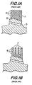
- Figure 1A illustrates a turbine rotor 5 wherein the original blade roots are machined off and a machined surface 3 has been prepared.
- Figure 1A also shows the same turbine rotor 5, wherein a single weld volume 1 is formed on the prepared surface 3 of the turbine rotor 5.
- the weld volume 1 consists of a plurality of individual weld beads 9, as shown in Figure 1A.
- a large portion of the deposited weld volume 1 is subsequently machined away, as illustrated in Figure 1B, to form a plurality of individual fingers 7 which are formed to interface with replacement turbine blades (not shown).
- a method of modifying or repairing a turbine component comprising the steps of providing a turbine rotor 5, preparing a welding surface 3 on the turbine rotor 5, and depositing weld wire metal 27 to form a plurality of individual spaced apart weld volumes 11, 13, 15, 17 on the prepared welding surface 3 or on a single weld volume or buffer 2, which is built up in accordance with the method of the prior art up to the point where the individual projections must start.
- This modernization or repair method further comprises the step of forming the plurality of individual spaced apart weld volumes 11, 13, 15, 17 to form a plurality of fingers 12, 14, 16, 18.
- the fingers 12, 14, 16, 18 are formed by machining the individual spaced apart weld volumes 11, 13, 15, 17.
- the step of depositing the weld wire metal 27 further comprises forming at least two of the individual spaced apart weld volumes 11, 13, 15, 17 concurrently and by maintaining a space 19 between the individual weld volumes 11, 13, 15, 17.
- the filler wire 27 may also be warmed or heated during the step of depositing by applying an electric current 25 to the filler wire 27 or by other appropriate means.
- Each of the pluralities of individual spaced apart weld volumes 11, 13, 15, 17 is formed by a plurality of layers 29 of said filler wire 27. Each layer 29 is formed from a single weld bead 28 or by a single pass of strip type weld material.
- the welding torches 21, 23 may be oscillated with an amplitude sufficient to form a predetermined weld volume width W and the torch is moved in relation to the repair surface at a predetermined rate to achieve the desired weld volume height H.
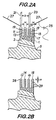
- FIGs 2A through 2B illustrate a modification or repair process in accordance with the present invention.
- Figure 2A illustrates a turbine rotor 5 wherein the original blade roots are machined off and a machined surface 3 has been prepared
- Preparation of the welding surface 3 comprises the steps of setting up the rotor 5 in a lathe, checking and recording critical dimensions of the rotor 5 for lathe reference, removing the old blades (if they have not already been cut out), removing the steeples or the blade attachments, and removing additional stock below the blade attachment which depends on where the heat affected zone should be placed.
- the welding surface 3 is then cleaned with a solvent and lint-free cloth to remove any oil, shavings, dirt, etc..
- a magnetic particle test is then performed to check for surface or near surface flaws so that the welding process wilt not cause cracking of the flaw.
- An ultrasonic test is performed to verify that there are no subsurface flaws either from the mill or that service conditions have not caused any flaws.
- the welding surface is then cleaned again.
- the weld area and the adjacent area of the component being repaired will normally be preheated prior to welding.
- Figure 2A also illusctrates a prepared rotor welding surface 3 wherein a plurality of individual spaced apart weld volumes 11, 13, 15, 17 are found on the prepared rotor welding surface 3 or on a single weld volume 2, which is built up in accordance with the method of the prior art up to the point where the individual projections must start.
- the single weld volume 2 can be considered equivalent to the prepared rotor welding surface 3, since it is an extension thereof and only employed to extend the surface of the rotor radially to the point where the steeples start.
- the plurality of the individual spaced apart weld volumes 11, 13, 15, 17 may be formed concurrently without the problems of arc blow and the interaction of proximate welding arcs due to the physical and magnetic separation between the welding arcs created by the space 19 between the individual spaced apart weld volumes 11, 13, 15, 17.
- arc instability known in the shop as "arc blow”
- pulsing the arc is accomplished by applying a pulsed current which creates a stiffer arc as compared to non-pulsing. This results in an arc that is not as sensitive to magnetic instabilities.
- the stiffer the arc column the better the resistance to arc instabilities.
- the best antidote is achieved by making the individual weld volumes 11, 13, 15, 17 because the electrical flux field is broken by making the various projections.
- arc blow is very noticeable where two or more torches are used, particularly the closer together the arcs are to each other.
- the only solution was to separate the torches by some distance.
- This new method of this invention solves this problem because once the buildup begins, the electrical flux field is broken. The higher the projections are the more the flux field is reduced.
- the plurality of individual spaced apart weld volumes 11, 13, 15, 17 separated by space 19 also provide less residual stress in the weld for the individual spaced apart weld volumes 11, 13, 15, 17 as opposed to one large weld volume 1 seen in Figure 1A of the prior art. This is because space 19 acts as a relief between the individual spaced apart weld volumes 11, 13, 15, 17. In addition, fewer weld beads result in less total heat input to the weldment.
- FIG 2A illustrates two welding torches 21, 23 being used singularly or simultaneously. However, any number of torches may be used simultaneously, depending on the requirements of the particular weld repair. In a preferred embodiment of this invention, four torches are used simultaneously. Ideally, the number of torches being used would match the number of individual spaced apart weld volumes that are required for the final repair product. The use of two torches may cut the welding time in half for any given weld. Also, the build-up of individual weld volumes 11, 13, 15, 17 separated by spaces 19, as illustrated in Figure 2A, reduces the overall amount of weld metal which must be deposited when compared to the prior art rectangular weld volume 1, as illustrated in Figure 1A. This depositing of individual spaced apart weld volumes 1, 13, 15, 17 using a plurality of weld torches 21, 23 reduces the welding time and subsequent machining time when compared to the prior art methods.
- Each weld volume 11, 13, 15, 17 may be formed by a plurality of layers 29 of deposited weld metal as illustrated in Figure 2A and Figure 2B.
- a solid base of weld metal is deposited to a desired height and then the individual spaced apart weld volumes are formed by a single weld bead 28 deposited in a single pass to form an entire layer 29 by oscillating the welding torch 21, 23 in a direction perpendicular to the direction of welding with a predetermined amplitude sufficient to form the desired weld bead width W. It is desired that the weld torches 21, 23 be oscillated in the same direction to maintain the maximum distance D between torches 21, 23 which further helps to reduce arc instability.
- strip materials and the use of extra long stickout provides improvements in both the weld metal deposition rates and improved weld properties.
- the filler wire 27 is heated.
- This technique of adding current to the filler metal in order to preheat the wire provides further improvements to the weld deposition by not chilling the weld pool with a "cold" wire.
- the wire is resistance heated by alternating current from a constant-voltage power source to a temperature close to its melting point just before it contacts the molten weld pool. Normally this type of process results in very poor Charpy V-notch toughness properties because it forms large weld beads which cool very slowly, thereby causing large grain growth and subsequently low Charpy impact values.
- the plurality of fingers 12, 14, 16, 18 are formed from the plurality of individual spaced apart weld volumes 11, 13, 15, 17 by machining.
- the step of machining the plurality of individual spaced apart weld volumes into a plurality of fingers comprises the steps of setting the repaired rotor in a lathe and then performing three basic cuts. Three passes with a tool are performed and are known as a rough, semi-finish, and a finish cut. In all three cases, the beginning cut is the outside diameter, then the inside and outside faces (or the left and right outside faces). Next, the insides of the fingers are machined, in order going from left to right or right to left, depending on the machine setup. The inside finger work is known as a plunge cut. Afterwards, the radius cuts are made, that is the top and bottom radius for each finger.
- An embodiment of this invention uses two torches to form two welds simultaneously, each weld having a wing current of about 30-70 amperes with a 0.045" to 0.062" (1.143 to 1.575 mm) diameter welding wire 27 being oscillated at about 0.4 to 1,2 inches (10.2 to 30.5 mm) at an oscillation rate of about 0.4 to 0.8 cycles per second (Hertz) and a welding speed of about 2.5 to 3.6 inches per minute (1.06 to 1.52 mm/sec) with a wire feed rate of about 65 to 250 ipm (2.75 to 10.6 cm/sec) to form a weld bead width (W) of approximately 0.5 to 1.5 inches (1.27 to 3.81 cm).
- strip for the modernization and repair of steeples.
- the use of strip in the turbine rotor modernization or repair process provides lower cost and cycle times by enabling the work to be completed faster thereby allowing the component to be returned to service in a shorter amount of time. Due to differences in blade design, these various blades design require different amounts of weld metal to be deposited.
- the use of strip allows for an increased weld deposition rate.
- the use of high purity strip material also produces a high quality weld.
- the repair is effectuated using strip of a particular width which corresponds to the width or shape of the required weld repair.
- strip of a particular width which corresponds to the width or shape of the required weld repair.
- the use of multiple strips passes side by side to obtain the necessary weld width may be employed.
- This application of laying multiple strips side by side is due to limitations in the manufacturing and availability of strip width.
- This modernization or repair method would be applicable to either high pressure or low pressure rotors and turbine components.
- a 360 degree (6.3 radians) weld build-up is deposited on a prepared surface.
- the number of passes around the rotor is determined by the repair being effectuated and the desired height of the blade attachments.
- one pass of the strip would equal one layer and the strip would be selected so that the width of the strip provided the desired width for the final weld.
- Each subsequent pass acts to heat treat and temper the previous pass thereby improving the characteristics of the weld.
- Low pressure rotor welds are made on all parts of the rotor forging and on various disc forgings.
- the strip material and welding process employed help to determine the various properties of the resulting weld.
- Some of the weld properties that are of concern are high-cycle fatigue, stress corrosion cracking, toughness, fracture mechanics, and the geometry of the weldment.
- the majority of weld repairs that have been made on high-pressure turbine alloys have been in the area of the control stage. These modernizations or repairs have typically been made to effectuate a design change to side entry or triple pin configuations.
- This area of the rotor experiences high temperatures and stresses as a result of high pressure steam passing over these areas.
- the resulting weld volume is machined using traditional techniques to provide the desired blade attachment.
- straight-side entry or curved side-entry, inverted T-slot, or various pinned configurations are machined into the weld volume to provide the desired means for blade attachment.
Landscapes
- Engineering & Computer Science (AREA)
- Mechanical Engineering (AREA)
- General Engineering & Computer Science (AREA)
- Physics & Mathematics (AREA)
- Plasma & Fusion (AREA)
- Arc Welding In General (AREA)
- Butt Welding And Welding Of Specific Article (AREA)
- Turbine Rotor Nozzle Sealing (AREA)
Applications Claiming Priority (3)
| Application Number | Priority Date | Filing Date | Title |
|---|---|---|---|
| US136848 | 1998-08-19 | ||
| US09/136,848 US6118098A (en) | 1997-10-10 | 1998-08-19 | Turbine rotor modernization and repair method |
| PCT/US1999/018916 WO2000010765A1 (en) | 1998-08-19 | 1999-08-18 | Turbine rotor modernization and repair method |
Publications (2)
| Publication Number | Publication Date |
|---|---|
| EP1105243A1 EP1105243A1 (en) | 2001-06-13 |
| EP1105243B1 true EP1105243B1 (en) | 2003-04-23 |
Family
ID=22474648
Family Applications (1)
| Application Number | Title | Priority Date | Filing Date |
|---|---|---|---|
| EP99942328A Expired - Lifetime EP1105243B1 (en) | 1998-08-19 | 1999-08-18 | Turbine rotor modernization and repair method |
Country Status (8)
| Country | Link |
|---|---|
| US (1) | US6118098A (https=) |
| EP (1) | EP1105243B1 (https=) |
| JP (1) | JP4675482B2 (https=) |
| KR (1) | KR100624996B1 (https=) |
| CN (1) | CN1313800A (https=) |
| CA (1) | CA2340932C (https=) |
| DE (1) | DE69907215T2 (https=) |
| WO (1) | WO2000010765A1 (https=) |
Families Citing this family (41)
| Publication number | Priority date | Publication date | Assignee | Title |
|---|---|---|---|---|
| US6536110B2 (en) * | 2001-04-17 | 2003-03-25 | United Technologies Corporation | Integrally bladed rotor airfoil fabrication and repair techniques |
| JP2004181480A (ja) * | 2002-12-02 | 2004-07-02 | Mitsubishi Heavy Ind Ltd | タービン用ロータの補修方法 |
| GB0302399D0 (en) * | 2003-02-03 | 2003-03-05 | Rolls Royce Plc | Laser deposition |
| US8266800B2 (en) | 2003-09-10 | 2012-09-18 | Siemens Energy, Inc. | Repair of nickel-based alloy turbine disk |
| DE102004036066A1 (de) * | 2004-07-24 | 2006-02-16 | Mtu Aero Engines Gmbh | Verfahren zum Reparieren bzw. Fertigen eines Bauteils |
| US7316057B2 (en) * | 2004-10-08 | 2008-01-08 | Siemens Power Generation, Inc. | Method of manufacturing a rotating apparatus disk |
| FR2882533B1 (fr) * | 2005-02-25 | 2007-07-06 | Snecma Moteurs Sa | Procede de reparation de disque aubage monobloc, eprouvette de debut et de fin campagne |
| US20060231535A1 (en) * | 2005-04-19 | 2006-10-19 | Fuesting Timothy P | Method of welding a gamma-prime precipitate strengthened material |
| US20070267109A1 (en) * | 2006-05-17 | 2007-11-22 | General Electric Company | High pressure turbine airfoil recovery device and method of heat treatment |
| US20080263863A1 (en) * | 2007-04-27 | 2008-10-30 | United Technologies Corporation | Dimensional restoration of turbine blade knife edge seals |
| US20090014421A1 (en) * | 2007-07-10 | 2009-01-15 | Sujith Sathian | Weld Repair Method for a Turbine Bucket Tip |
| GB2452274A (en) * | 2007-08-30 | 2009-03-04 | Welding Alloys Ltd | Manufacture of welded components |
| EP2100687A1 (de) * | 2008-02-29 | 2009-09-16 | Siemens Aktiengesellschaft | Potentialfreie Drahterwärmung beim Schweissen und Vorrichtung dafür |
| FR2931714B1 (fr) * | 2008-05-30 | 2010-06-25 | Snecma | Construction d'une partie d'une piece metallique par le procede mig avec courant et fil pulses |
| US8678267B2 (en) * | 2008-10-10 | 2014-03-25 | The Boeing Company | System and method for integrally forming a stiffener with a fiber metal laminate |
| DE102011002532A1 (de) * | 2011-01-11 | 2012-07-12 | Rolls-Royce Deutschland Ltd & Co Kg | Verfahren zur Reparatur von Verdichter- oder Turbinentrommeln |
| RU2014118917A (ru) * | 2011-11-16 | 2015-12-27 | Лист АГ | Способ присоединения функциональных элементов в валу |
| US9126287B2 (en) | 2012-03-12 | 2015-09-08 | Siemens Energy, Inc. | Advanced pass progression for build-up welding |
| US20140053403A1 (en) * | 2012-08-22 | 2014-02-27 | General Electric Company | Method for extending an original service life of gas turbine components |
| US8726610B2 (en) * | 2012-08-29 | 2014-05-20 | General Electric Company | Crack-resistant member, a method of preventing crack propagation, and a method of assembling a tower |
| US9676051B2 (en) * | 2012-10-18 | 2017-06-13 | Lincoln Global, Inc. | System and methods providing modulation schemes for achieving a weld bead appearance |
| US20140151481A1 (en) * | 2012-12-03 | 2014-06-05 | Basf Se | Process for Connecting Functional Elements to a Shelf |
| EP2756907A1 (de) * | 2013-01-21 | 2014-07-23 | Siemens Aktiengesellschaft | Auftragsschweißen mit äußerer dickerer Rahmenkontur |
| US20160032766A1 (en) * | 2013-03-14 | 2016-02-04 | General Electric Company | Components with micro cooled laser deposited material layer and methods of manufacture |
| CN104002016A (zh) * | 2013-12-15 | 2014-08-27 | 柳州市柳南区旭升机械厂 | 装载机铲斗主刀板的表面硬化处理方法 |
| CN106715022B (zh) * | 2014-11-18 | 2019-11-12 | 株式会社小松制作所 | 耐磨损部件及其制造方法 |
| US9938834B2 (en) | 2015-04-30 | 2018-04-10 | Honeywell International Inc. | Bladed gas turbine engine rotors having deposited transition rings and methods for the manufacture thereof |
| US10294804B2 (en) * | 2015-08-11 | 2019-05-21 | Honeywell International Inc. | Dual alloy gas turbine engine rotors and methods for the manufacture thereof |
| CN106563929B (zh) * | 2015-10-08 | 2019-09-17 | 利宝地工程有限公司 | 修复和制造涡轮发动机部件的方法及涡轮发动机部件 |
| US10036254B2 (en) | 2015-11-12 | 2018-07-31 | Honeywell International Inc. | Dual alloy bladed rotors suitable for usage in gas turbine engines and methods for the manufacture thereof |
| DE102017103066A1 (de) * | 2017-02-15 | 2018-08-16 | Flottweg Se | Verfahren zum Herstellen eines metallischen Werkstücks |
| US11084275B2 (en) * | 2017-05-05 | 2021-08-10 | Lincoln Global, Inc. | Methods and systems for hybrid deposition rate near net shape additive manufacturing |
| JP6802773B2 (ja) * | 2017-10-23 | 2020-12-23 | 株式会社神戸製鋼所 | 積層造形物の製造方法及び積層造形物 |
| HUE069162T2 (hu) * | 2018-01-30 | 2025-02-28 | General Electric Technology Gmbh | Gázturbinamembrán javítása |
| CN108941858B (zh) * | 2018-09-04 | 2020-08-07 | 中国人民解放军陆军装甲兵学院 | 一种断裂板件mig弧焊增材再制造方法 |
| EP4259905B1 (en) * | 2020-12-08 | 2025-01-29 | General Electric Technology GmbH | Methods of forming or repairing part with overhung section, and related turbomachine part |
| EP4329968A4 (en) * | 2021-04-26 | 2025-05-21 | Optomec, Inc. | PROCESS FOR WELDING GAMMA-STRENGTHENED SUPERALLOYS AND OTHER CRACK-PRONE MATERIALS |
| GB202208609D0 (en) * | 2022-06-13 | 2022-07-27 | Rolls Royce Plc | Repair system and method for in-situ repair of machine |
| KR102458041B1 (ko) | 2022-08-05 | 2022-10-24 | 터보파워텍(주) | 초음파 진동과 레이저 클래딩을 이용한 터빈로터 수리방법 |
| KR102515276B1 (ko) | 2022-08-05 | 2023-03-29 | 터보파워텍(주) | 지그장치를 이용한 터빈로터 레이저 클래딩 수리방법 |
| KR102480317B1 (ko) | 2022-09-02 | 2022-12-23 | 터보파워텍(주) | 터빈로터 수리용 레이저 클래딩 자동화장치 |
Family Cites Families (15)
| Publication number | Priority date | Publication date | Assignee | Title |
|---|---|---|---|---|
| JPS5017349A (https=) * | 1973-06-19 | 1975-02-24 | ||
| DE2542081A1 (de) * | 1975-09-20 | 1977-03-24 | Krupp Gmbh | Verfahren und vorrichtung zur herstellung dickwandiger werkstuecke aus stahl |
| CH594471A5 (https=) * | 1976-07-02 | 1978-01-13 | Bbc Brown Boveri & Cie | |
| DE3430114C2 (de) * | 1984-08-16 | 1986-12-18 | J.M. Voith Gmbh, 7920 Heidenheim | Vorrichtung zum Aufbauen eines Werkstücks durch Auftragschweißen |
| US4590358A (en) * | 1984-10-04 | 1986-05-20 | Unimation, Inc. | Apparatus for electrically isolated hot wire surfacing processes |
| US4657171A (en) * | 1985-06-13 | 1987-04-14 | General Electric Company | Repair of a member having a projection |
| US4633554A (en) * | 1985-08-08 | 1987-01-06 | Westinghouse Electric Corp. | Method for repairing a steam turbine or generator rotor |
| JPS62282796A (ja) * | 1986-05-29 | 1987-12-08 | Mitsubishi Heavy Ind Ltd | 翼根部溶接補修法 |
| US4958431A (en) * | 1988-03-14 | 1990-09-25 | Westinghouse Electric Corp. | More creep resistant turbine rotor, and procedures for repair welding of low alloy ferrous turbine components |
| US4897519A (en) * | 1988-03-14 | 1990-01-30 | Westinghouse Electric Co. | More creep resistant turbine rotor, and procedures for repear welding of low alloy ferrous turbine components |
| US4940390A (en) * | 1988-05-05 | 1990-07-10 | Westinghouse Electric Corp. | Turbine system having more failure resistant rotors and repair welding of low alloy ferrous turbine components by controlled weld build-up |
| US4903888A (en) * | 1988-05-05 | 1990-02-27 | Westinghouse Electric Corp. | Turbine system having more failure resistant rotors and repair welding of low alloy ferrous turbine components by controlled weld build-up |
| US5024582A (en) * | 1990-08-14 | 1991-06-18 | Westinghouse Electric Corp. | Steam turbine rotor having graded weldments |
| US5735044A (en) * | 1995-12-12 | 1998-04-07 | General Electric Company | Laser shock peening for gas turbine engine weld repair |
| US5914055A (en) * | 1996-11-18 | 1999-06-22 | Tennessee Valley Authority | Rotor repair system and technique |
-
1998
- 1998-08-19 US US09/136,848 patent/US6118098A/en not_active Expired - Lifetime
-
1999
- 1999-08-18 CA CA002340932A patent/CA2340932C/en not_active Expired - Fee Related
- 1999-08-18 JP JP2000566070A patent/JP4675482B2/ja not_active Expired - Fee Related
- 1999-08-18 KR KR1020017002105A patent/KR100624996B1/ko not_active Expired - Fee Related
- 1999-08-18 DE DE69907215T patent/DE69907215T2/de not_active Expired - Lifetime
- 1999-08-18 WO PCT/US1999/018916 patent/WO2000010765A1/en not_active Ceased
- 1999-08-18 EP EP99942328A patent/EP1105243B1/en not_active Expired - Lifetime
- 1999-08-18 CN CN99809843A patent/CN1313800A/zh active Pending
Also Published As
| Publication number | Publication date |
|---|---|
| KR100624996B1 (ko) | 2006-09-20 |
| CN1313800A (zh) | 2001-09-19 |
| JP2002523240A (ja) | 2002-07-30 |
| DE69907215D1 (de) | 2003-05-28 |
| DE69907215T2 (de) | 2003-10-30 |
| WO2000010765A1 (en) | 2000-03-02 |
| WO2000010765B1 (en) | 2000-05-04 |
| US6118098A (en) | 2000-09-12 |
| KR20010085411A (ko) | 2001-09-07 |
| CA2340932A1 (en) | 2000-03-02 |
| EP1105243A1 (en) | 2001-06-13 |
| CA2340932C (en) | 2009-03-31 |
| JP4675482B2 (ja) | 2011-04-20 |
Similar Documents
| Publication | Publication Date | Title |
|---|---|---|
| EP1105243B1 (en) | Turbine rotor modernization and repair method | |
| USRE37562E1 (en) | Turbine system having more failure resistant rotors and repair welding of low alloy ferrous turbine components by controlled weld build-up | |
| US4940390A (en) | Turbine system having more failure resistant rotors and repair welding of low alloy ferrous turbine components by controlled weld build-up | |
| US4897519A (en) | More creep resistant turbine rotor, and procedures for repear welding of low alloy ferrous turbine components | |
| US4958431A (en) | More creep resistant turbine rotor, and procedures for repair welding of low alloy ferrous turbine components | |
| US6673169B1 (en) | Method and apparatus for repairing superalloy components | |
| EP1148967B1 (en) | Laser welding superalloy articles | |
| EP1916051B1 (en) | Method of repairing an aperture and defect in a part with welding using an insert with top and runoff plates and backing | |
| US5479704A (en) | Process for repairing damaged blades of turboengines | |
| US5831241A (en) | Optimized welding technique for NiMoV rotors for high temperature applications | |
| US9085042B2 (en) | Stud welding repair of superalloy components | |
| CN120002307A (zh) | 一种航空发动机叶片叶冠耐磨层磨损的修复方法 | |
| CN1036617A (zh) | 高抗蠕变汽轮机转子及低合金铁基汽轮机部件焊接修复的方法 | |
| EP4711065A1 (en) | Weld repair of steel alloy components | |
| Hauer et al. | Cladding of submerged propeller shafts: a comparison between conventional and high end techniques and materials | |
| Frederick et al. | Laser Weld Repair of Service Exposed IN738 and GTD111 Buckets |
Legal Events
| Date | Code | Title | Description |
|---|---|---|---|
| PUAI | Public reference made under article 153(3) epc to a published international application that has entered the european phase |
Free format text: ORIGINAL CODE: 0009012 |
|
| 17P | Request for examination filed |
Effective date: 20010312 |
|
| AK | Designated contracting states |
Kind code of ref document: A1 Designated state(s): DE FR GB IT |
|
| GRAH | Despatch of communication of intention to grant a patent |
Free format text: ORIGINAL CODE: EPIDOS IGRA |
|
| GRAH | Despatch of communication of intention to grant a patent |
Free format text: ORIGINAL CODE: EPIDOS IGRA |
|
| GRAA | (expected) grant |
Free format text: ORIGINAL CODE: 0009210 |
|
| AK | Designated contracting states |
Designated state(s): DE FR GB IT |
|
| REG | Reference to a national code |
Ref country code: GB Ref legal event code: FG4D |
|
| REF | Corresponds to: |
Ref document number: 69907215 Country of ref document: DE Date of ref document: 20030528 Kind code of ref document: P |
|
| ET | Fr: translation filed | ||
| PLBE | No opposition filed within time limit |
Free format text: ORIGINAL CODE: 0009261 |
|
| STAA | Information on the status of an ep patent application or granted ep patent |
Free format text: STATUS: NO OPPOSITION FILED WITHIN TIME LIMIT |
|
| 26N | No opposition filed |
Effective date: 20040126 |
|
| REG | Reference to a national code |
Ref country code: DE Ref legal event code: R082 Ref document number: 69907215 Country of ref document: DE Representative=s name: PETER BERG, DE |
|
| REG | Reference to a national code |
Ref country code: DE Ref legal event code: R082 Ref document number: 69907215 Country of ref document: DE Representative=s name: BERG, PETER, DIPL.-ING., DE Effective date: 20111028 Ref country code: DE Ref legal event code: R081 Ref document number: 69907215 Country of ref document: DE Owner name: SIEMENS ENERGY, INC., ORLANDO, US Free format text: FORMER OWNER: SIEMENS WESTINGHOUSE POWER CORP., ORLANDO, FLA., US Effective date: 20111028 |
|
| REG | Reference to a national code |
Ref country code: FR Ref legal event code: CD Owner name: SIEMENS ENERGY, INC. Effective date: 20120413 |
|
| REG | Reference to a national code |
Ref country code: FR Ref legal event code: PLFP Year of fee payment: 17 |
|
| PGFP | Annual fee paid to national office [announced via postgrant information from national office to epo] |
Ref country code: GB Payment date: 20150812 Year of fee payment: 17 |
|
| PGFP | Annual fee paid to national office [announced via postgrant information from national office to epo] |
Ref country code: FR Payment date: 20150818 Year of fee payment: 17 |
|
| PGFP | Annual fee paid to national office [announced via postgrant information from national office to epo] |
Ref country code: IT Payment date: 20150825 Year of fee payment: 17 |
|
| PGFP | Annual fee paid to national office [announced via postgrant information from national office to epo] |
Ref country code: DE Payment date: 20151016 Year of fee payment: 17 |
|
| REG | Reference to a national code |
Ref country code: DE Ref legal event code: R119 Ref document number: 69907215 Country of ref document: DE |
|
| GBPC | Gb: european patent ceased through non-payment of renewal fee |
Effective date: 20160818 |
|
| REG | Reference to a national code |
Ref country code: FR Ref legal event code: ST Effective date: 20170428 |
|
| PG25 | Lapsed in a contracting state [announced via postgrant information from national office to epo] |
Ref country code: FR Free format text: LAPSE BECAUSE OF NON-PAYMENT OF DUE FEES Effective date: 20160831 Ref country code: GB Free format text: LAPSE BECAUSE OF NON-PAYMENT OF DUE FEES Effective date: 20160818 Ref country code: DE Free format text: LAPSE BECAUSE OF NON-PAYMENT OF DUE FEES Effective date: 20170301 |
|
| PG25 | Lapsed in a contracting state [announced via postgrant information from national office to epo] |
Ref country code: IT Free format text: LAPSE BECAUSE OF NON-PAYMENT OF DUE FEES Effective date: 20160818 |