EP1104728A2 - Sicherheitseinrichtung an einem Fahrzeug zum Schutz von Fussgängern - Google Patents
Sicherheitseinrichtung an einem Fahrzeug zum Schutz von Fussgängern Download PDFInfo
- Publication number
- EP1104728A2 EP1104728A2 EP00123468A EP00123468A EP1104728A2 EP 1104728 A2 EP1104728 A2 EP 1104728A2 EP 00123468 A EP00123468 A EP 00123468A EP 00123468 A EP00123468 A EP 00123468A EP 1104728 A2 EP1104728 A2 EP 1104728A2
- Authority
- EP
- European Patent Office
- Prior art keywords
- front hood
- hinge part
- safety device
- energy absorption
- deformation element
- Prior art date
- Legal status (The legal status is an assumption and is not a legal conclusion. Google has not performed a legal analysis and makes no representation as to the accuracy of the status listed.)
- Granted
Links
- 238000010521 absorption reaction Methods 0.000 claims abstract description 48
- 230000006835 compression Effects 0.000 claims description 8
- 238000007906 compression Methods 0.000 claims description 8
- 230000000284 resting effect Effects 0.000 claims description 4
- 239000002184 metal Substances 0.000 claims description 3
- 239000003380 propellant Substances 0.000 claims description 2
- 238000007664 blowing Methods 0.000 claims 1
- 238000006073 displacement reaction Methods 0.000 description 10
- 230000003116 impacting effect Effects 0.000 description 4
- 238000009434 installation Methods 0.000 description 4
- 230000001133 acceleration Effects 0.000 description 2
- 230000005540 biological transmission Effects 0.000 description 2
- 238000002485 combustion reaction Methods 0.000 description 2
- 238000010276 construction Methods 0.000 description 2
- 238000004146 energy storage Methods 0.000 description 2
- 230000002349 favourable effect Effects 0.000 description 2
- 238000004519 manufacturing process Methods 0.000 description 2
- 239000004604 Blowing Agent Substances 0.000 description 1
- 230000004913 activation Effects 0.000 description 1
- 230000008901 benefit Effects 0.000 description 1
- 230000015572 biosynthetic process Effects 0.000 description 1
- 230000008878 coupling Effects 0.000 description 1
- 238000010168 coupling process Methods 0.000 description 1
- 238000005859 coupling reaction Methods 0.000 description 1
- 238000013016 damping Methods 0.000 description 1
- 230000006735 deficit Effects 0.000 description 1
- 230000009467 reduction Effects 0.000 description 1
- 230000002441 reversible effect Effects 0.000 description 1
- 230000001960 triggered effect Effects 0.000 description 1
Images

Classifications
-
- B—PERFORMING OPERATIONS; TRANSPORTING
- B60—VEHICLES IN GENERAL
- B60R—VEHICLES, VEHICLE FITTINGS, OR VEHICLE PARTS, NOT OTHERWISE PROVIDED FOR
- B60R21/00—Arrangements or fittings on vehicles for protecting or preventing injuries to occupants or pedestrians in case of accidents or other traffic risks
- B60R21/34—Protecting non-occupants of a vehicle, e.g. pedestrians
- B60R21/38—Protecting non-occupants of a vehicle, e.g. pedestrians using means for lifting bonnets
-
- B—PERFORMING OPERATIONS; TRANSPORTING
- B60—VEHICLES IN GENERAL
- B60R—VEHICLES, VEHICLE FITTINGS, OR VEHICLE PARTS, NOT OTHERWISE PROVIDED FOR
- B60R21/00—Arrangements or fittings on vehicles for protecting or preventing injuries to occupants or pedestrians in case of accidents or other traffic risks
- B60R21/34—Protecting non-occupants of a vehicle, e.g. pedestrians
- B60R2021/343—Protecting non-occupants of a vehicle, e.g. pedestrians using deformable body panel, bodywork or components
Definitions
- the invention relates to a safety device on a vehicle for the protection of Pedestrians according to the preamble of claim 1.
- JP 009 031 5266 and DE 197 10 417 A1 each have one Known safety device in which a front hood in the event of an impending or collision with a pedestrian from a bonnet resting position into one this is raised compared to the raised bonnet impact position.
- This will a hinge arrangement of the bonnet arranged in the rear front section raised by means of a cylinder-piston unit, whereby the front hood by one horizontal pivot axis in the front area of the vehicle is pivoted so that the Front bonnet in the rear front section from a bonnet resting position to one The bonnet impact position is raised.
- a similar structure is known from FR-A 2 772 700, in which one Pedestrian impact the bonnet hinge assembly through a spring assembly is raised from the rest position to the impact position.
- Building a Safety device with a spring arrangement is also from DE 197 12 961 A1 known in which the hinge arrangement is designed as a four-bar arrangement and a hinged hinge bracket in the event of a collision with the vehicle a pedestrian can be pivoted upwards via the spring arrangement.
- the distance is also in the event of a collision between the vehicle and a pedestrian the front hood to the vehicle parts underneath, but is disadvantageous also here that no energy absorption is possible with a targeted force / displacement identifier is.
- due to the spring arrangement there is a risk that the Front hood springs back up after a first lowering. This can the impact is uncontrolled in an undesirable manner.
- a certain Acceleration-time behavior for the impacting pedestrian can also here cannot be achieved.
- a generic safety device on a vehicle to protect Pedestrians with an energy absorption option is from DE-OS 28 41 315 known, which comprises a hinge arrangement, by means of which a front hood, preferably on both sides of a vehicle and preferably in a rear Front end area is pivotally hinged to the vehicle, the Hinge arrangement a front hood-side hinge part and a body-side Hinge part includes.
- This safety device further includes Energy absorption element for targeted energy absorption in a Pedestrian impact on the front hood.
- a cylinder-piston unit via which a sensed one Collision of the vehicle with a pedestrian the front hood is raised.
- the Energy absorption element consists of arranged in a circumferential groove of the piston Balls raised at one by the impact of the pedestrian on the Front hood caused the piston to move back on a tapered Run up ramp of the piston and a clamping of the piston in the cylinder cause.
- the object of the invention is therefore to provide a safety device on a vehicle Protection of pedestrians to create a pedestrian impact Enables energy absorption with targeted force-displacement identification.
- the energy absorption element is a deformation element formed and the hinge assembly coupled to the deformation element, so that in the event of a pedestrian impact on the front hood, the front hood side Hinge part and thus the front hood with energy absorption relative to The vehicle body can be lowered downward in a targeted manner by the deformation element.
- Front hood in a preferred embodiment in a front hood rest position spaced above a body level. This has the advantage that no additional measures have to be provided to the front hood in rear front section from the bonnet resting position to a bonnet impact position to raise.
- a Sensor device for detecting an impending or occurring collision with a Pedestrians can be arranged, wherein one can be activated by the sensor device
- Energy storage for adjusting a bonnet of the vehicle from the bonnet rest position in a raised front hood impact position is provided. This makes the distance of the deformable and thereby energy absorbing front hood to the underlying, non-deformable Vehicle parts increased, so that an overall larger deformation path is available stands.
- the front hood-side hinge part and / or the body-side hinge part is designed as a deformation element. It is advantageous here that the respective hinge part also functions as a double function Deformation element can be used. This leads to a desired one Component reduction, making the safety device overall easier and faster and is therefore also cheaper to manufacture. Furthermore, a Safety device in which the front hood side and / or the body side Hinge part is designed as a deformation element, also a cheap and advantageous energy absorption with a targeted force / displacement identifier, one targeted introduction of force into the respective hinge part takes place as a deformation element.
- the front hinge part and the body hinge part in Seen in the longitudinal direction of the vehicle are spaced apart, preferably by one hinge part closer to the front of the vehicle.
- the the front-side hinge part and the body-side hinge part are over a connecting arm connected to each other, this connecting arm preferably arcuate, that is curved concavely downwards is trained.
- This connecting arm is preferred with a connecting arm end firmly connected to the front hinge part and preferably with the rear link arm articulated to the body-side hinge part.
- this is the body-side and / or the hinge part on the front hood as a deformation element, preferably as a sheet metal deformation element, educated.
- a deformation element preferably as a sheet metal deformation element, educated.
- This ensures that the body side and / or the front hood-side hinge part as a deformation element in one Pedestrian impact on the front hood with targeted energy absorption on simple Way through targeted compression and / or kinking and / or folding from one undeformed normal position can be converted into a deformed deformed position.
- Such a structure is simple and inexpensive with good functional reliability, that is with favorable and advantageous energy absorption with a targeted force / displacement identifier.
- a connecting arm between the front hood side and the body side hinge part includes the rear Connecting arm end in the connection area to the body-side hinge part Guide pin, which is in a somewhat vertically aligned guide link of the body-side hinge part is guided.
- the connecting arm cooperates an energy storage together, which in the activated state from the guide pin a lower starting position in a position opposite this in the Raises the guide link so that the connecting arm removes the front cover from the Raises the bonnet rest position to the bonnet impact position.
- Gas bag devices that can be triggered by the sensor device and that enable additional damping can be provided as energy stores.
- a cylinder-piston unit is provided as an energy store for a targeted lifting of the front hood.
- Such a cylinder-piston unit comprises a piston rod with a piston which is guided in a cylinder of the cylinder-piston unit.
- the activation can take place, for example, by pyrotechnic means.
- the piston rod of the cylinder-piston unit is coupled with its free end to the connecting arm and the cylinder is connected to a connection point on the body side.
- the cylinder can be arranged fixedly on the body-side connection point or can also be pivoted.
- the coupling of the piston rod to the connecting arm can take place, for example, via a positive receiving connection.
- connection point can be used as a deformation element be formed, the cylinder-piston unit in the event of a pedestrian impact on the Front hood with extended due to a piston backstop pushed out piston rod is lowerable, so that Deformation element due to the connection of the cylinder-piston unit under targeted Energy absorption from an undeformed normal position through compression and / or Kinking and / or folding can be converted into a deformed deformed position.
- the front hood is due to the positive guidance of the guide pin in the Leadership backdrop can be lowered downwards.
- the Safety device results in a particularly advantageous energy absorption due to the targeted introduction of force and the targeted redirection of force, so that too a targeted force / displacement identifier is achieved.
- the connecting arm preferably in a middle and / or the front hood side Area of the connecting element facing the hinge part as a deformation element is designed in the form of a predetermined kink.
- the cylinder-piston unit keeps one Pedestrian impact on the front hood by a piston backstop extended state with the piston rod pushed out so that when Pedestrian impact on the front cover of the connecting arm in the area of the predetermined kink kinks with targeted energy absorption.
- the cylinder-piston unit gives you one Pedestrian impact on the front hood in the manner of a deformation element force-limited after, preferably with this force-limited yielding Example gas is blown out as a blowing agent.
- the one that forms the fender Body area at least in the fender area near the front hood as Deformation part formed so that it is designed as a deformation part Body area in the event of a pedestrian impact on the front hood under targeted Energy absorption through compression and / or kinking and / or folding from one undeformed normal position can be converted into a deformed deformed position.
- a structure of the fender area near the hood as Deformation part is achieved that the area adjacent to the front hood as Deformation area is available, so that overall a large area Impact area is created for a targeted energy absorption. This allows particularly advantageous results with regard to a targeted force / displacement identification targeted force transmission and targeted force redirection as part of energy absorption achieve.
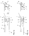
- FIG. 1a is a schematic side view and a front view of a first Embodiment of a safety device 1 in a bonnet rest position 2 shown.
- This safety device 1 comprises a hinge arrangement 3 by means of a front hood 4 is pivotally hinged to the vehicle.
- the front hood 4 is preferably on both sides of the vehicle in a rear front area articulated.
- the hinge arrangement 3 consists of a front hood-side hinge part 5 and a body-side hinge part 6, which is designed as a deformation element 7 in a double function.
- fender 10 forming Body area in the upper fender area near the bonnet on the inside is designed as a deformation part 11.
- FIG. 1a From the side view of Fig. 1a it can also be seen that the front hood side Hinge part 5 and the body-side hinge part 6 arranged one above the other are and are directly connected to each other in a pivot point 12, the Front hood 4 in the front hood rest position 2 shown in FIG. 1a with a Deformation distance D measured between the hinge part 5 on the front hood side and a body level 13 is arranged above the body level 13, wherein the deformation distance D is preferably approximately 80 mm.
- FIG. 1b In the event of a pedestrian impact on the front hood 4, as shown in FIG. 1b is shown schematically in a front view and in a side view Front hood 4 together with the front hood-side hinge part 5 under targeted Energy absorption by the body-side designed as a deformation element 7 Hinge part 6 lowered down, the deformation element 7 below Compression and folding from an undeformed normal position 14 into a deformed one Deformation position 15 is transferred.
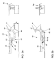
- FIG. 2a shows an alternative embodiment of a safety device 20 shown, in which a front hood 21 by means of a hinge arrangement 22nd is pivoted to the vehicle.
- the hinge assembly 22 also includes here again a hinge part 24 on the front hood side and a body-side one Hinge part 25, the body-side hinge part 25 here simultaneously in one Double function also as a deformation element 26, corresponding to the Embodiment of FIGS. 1a and 1b is formed.
- the front hood side Hinge part 24 and the body-side hinge part 25 are in the vehicle longitudinal direction seen from each other, the front hood-side hinge part 24 closer is arranged towards the front of the vehicle as the body-side hinge part 25.
- the hinge part 24 on the front hood side and the body-side hinge part 25 indirectly via a concave downward curved connecting arm 27 connected, said connecting arm 27 with a Connection arm end 28 on the front cover firmly with the front cover end Hinge part 24 is connected and to the opposite body side Connection arm end 29 is articulated on the body-side hinge part 25.
- an inner side is also here Mudguard 32 designed as a deformation part 33.
- the distance between an underside of the link arm 27 and one Body level 23 here is, for example, 80 mm.
- this safety device 20 essentially corresponds that of FIGS. 1a and 1b, as explained in more detail below with reference to FIG. 2b becomes:
- the deformation part 33 may also correspond to a pedestrian impact of the fender 32 are deformed with targeted energy absorption.
- FIG. 3a shows a further alternative embodiment of a safety device 40 shown, the structure of which is basically that of the safety device 20 of the 2a and 2b corresponds, with the difference that here is not a body side Hinge part 41 of a hinge arrangement 42, but a front hood side Hinge part 43 of the hinge arrangement 42 is designed as a deformation element 44.
- the hinge arrangement 42 here in turn comprises a connecting arm 45 which is connected to a connecting arm end 46 on the front hood firmly with the front hood side Hinge part 43 is connected and to a body-side connecting arm end 47 is pivotally hinged to the body-side hinge part 41.
- the connection of the body-side connecting arm end 47 to the body-side Hinge part 41 takes place in such a way that only an upward-facing, conventional one Opening the front hood 48 is possible, but a further lowering of the front hood 48 from the bonnet rest position 51 shown in FIG. 3a only below Force, such as. B. a pedestrian impact is possible.
- the Front hood 48 with a sufficient deformation distance D, preferably in about 80 mm, arranged above a body level 52.
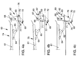
- the safety device 60 comprises one Front hood 61, which by means of a hinge arrangement 62, consisting of a body-side hinge part 63, a front hood-side hinge part 64 and a connecting arm 65 connecting them to a vehicle body is articulated.
- a rear connecting arm end comprises 66 in the connection area of the connecting arm 65 to the body side Hinge part 63 has a guide pin 67 which is aligned in an approximately vertical direction Guide link 69 of the body-side hinge part 63 is guided.
- the connecting arm 65 interacts with a cylinder-piston unit 69, the one Cylinder 70 and a piston rod 71 together with the piston not visible here comprises.
- the free end of the piston rod 71 is coupled to the connecting arm 65, while the cylinder 70 at a body-side connection point 72, which is approximately in Area below the body-side hinge part 63 is connected.
- the Connection point 72 is designed here as a deformation element, for example by a sheet metal fold.
- the sensor device In the vehicle front area there is also a sensor device for detecting a impending or collision with a pedestrian arranged, but here is not shown.
- the sensor device activates the cylinder-piston unit 69, for example through pyrotechnic ignition. This lifts the link arm 65 over the Extended piston rod 71 of the cylinder-piston unit 69 extends the front cover 61 a bonnet rest position 74 shown in FIG. 4a into a position shown in FIG. 4b the bonnet impact position 75 shown, with the guide pin 65 from a lower starting position shown in FIG. 4a to one of these opposite raised position in the guide link 68, as shown in FIG. 4b, is raised.
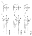
- FIGS. 5a to 5c each schematically show a side view and a front view of a fifth embodiment of a safety device 80, the structure of which essentially corresponds to the safety device 60 of FIGS. 4a to 4c, so that this will not be discussed in detail.
- a connection point 81 of a cylinder 82 of a cylinder-piston unit 83 is not designed as a deformation element, but instead a targeted energy absorption takes place in the event of a pedestrian impact by force-limited yielding of the cylinder-piston unit 83 as a deformation element.
- the propellant of the cylinder-piston unit for example a gas, is advantageously blown out of the cylinder-piston unit 83 during the energy absorption.
- the front hood can also be raised with a reversible spring arrangement, the energy absorption then e.g. B. done by the cylinder-piston unit.
Landscapes
- Engineering & Computer Science (AREA)
- Mechanical Engineering (AREA)
- Superstructure Of Vehicle (AREA)
- Lighting Device Outwards From Vehicle And Optical Signal (AREA)
- Body Structure For Vehicles (AREA)
Abstract
Description
Grundsätzlich ist es möglich, den Zylinder mit dem Verbindungsarm zu koppeln und die Kolbenstange mit ihrem freien Ende an einer karosserieseitigen Anbindungsstelle festzulegen. Günstige geometrische Einbauverhältnisse ergeben sich jedoch dann, wenn die Kolbenstange der Zylinder-Kolben-Einheit mit ihrem freien Ende mit dem Verbindungsarm gekoppelt ist und der Zylinder an einer karosserieseitigen Anbindungsstelle angebunden ist. Der Zylinder kann dabei, je nach Einbausituation und gewünschter Ausführungsform fest an der karosserieseitigen Anbindungsstelle angeordnet sein oder aber auch schwenkbar angelenkt sein. Die Kopplung der Kolbenstange mit dem Verbindungsarm kann zum Beispiel über eine formschlüssige Aufnahmeverbindung erfolgen.
- Fig. 1a-1b
- jeweils eine schematische Seitenansicht und Vorderansicht einer ersten Ausführungsform der Sicherheitseinrichtung vor und nach einem Fußgängeraufprall,
- Fig. 2a-2b
- jeweils eine schematische Seitenansicht und Vorderansicht einer zweiten Ausführungsform der Sicherheitseinrichtung vor und nach einem Fußgängeraufprall,
- Fig. 3a-3b
- jeweils eine schematische Seitenansicht und Vorderansicht einer dritten Ausführungsform der Sicherheitseinrichtung vor und nach einem Fußgängeraufprall,
- Fig. 4a-4c
- jeweils eine schematische Seitenansicht einer vierten Ausführungsform der Sicherheitseinrichtung vor und nach einem Fußgängeraufprall, und
- Fig. 5a-5c
- jeweils eine schematische Seitenansicht und Vorderansicht einer fünften Ausführungsform der Sicherheitseinrichtung vor und nach einem Fußgängeraufprall.
In den Fig. 5a bis 5c ist schematisch jeweils eine Seitenansicht und eine Vorderansicht einer fünften Ausführungsform einer Sicherheitseinrichtung 80 dargestellt, die vom Aufbau her im wesentlichen der Sicherheitseinrichtung 60 der Fig. 4a bis 4c entspricht, so dass hierauf nicht mehr detailliert eingegangen wird. Im Unterschied zu der Sicherheitseinrichtung 60 der Fig. 4a bis 4c ist hier eine Anbindungsstelle 81 eines Zylinders 82 einer Zylinder-Kolben-Einheit 83 nicht als Deformationselement ausgebildet, sondern erfolgt bei einem Fußgängeraufprall eine gezielte Energieabsorption durch kraftbegrenztes Nachgeben der Zylinder-Kolben-Einheit 83 als Deformationselement. Vorteilhaft wird dabei das Treibmittel der Zylinder-Kolben-Einheit, zum Beispiel ein Gas, während der Energieabsorption aus der Zylinder-Kolben-Einheit 83 ausgeblasen. Alternativ kann bei diesen Ausführungsformen die Fronthaube auch mit einer reversiblen Federanordnung angehoben werden, wobei die Energieabsorption dann z. B. durch die Zylinder-Kolben-Einheit erfolgt.
- 1
- Sicherheitseinrichtung
- 2
- Fronthauben-Ruheposition
- 3
- Scharnieranordnung
- 4
- Fronthaube
- 5
- fronthaubenseitiges Scharnierteil
- 6
- karosserieseitiges Scharnierteil
- 7
- Deformationselement
- 8
- Kotflügelbank
- 9
- Fahrzeugkarosserie
- 10
- Kotflügel
- 11
- Deformationsteil
- 12
- Anlenkstelle
- 13
- Karosserieebene
- 14
- Normalstellung
- 15
- Deformationsstellung
- 20
- Sicherheitseinrichtung
- 21
- Fronthaube
- 22
- Scharnieranordnung
- 23
- Karosserieebene
- 24
- fronthaubenseitiges Scharnierteil
- 25
- karosserieseitiges Scharnierteil
- 26
- Deformationselement
- 27
- Verbindungsarm
- 28
- Verbindungsarmende
- 29
- Verbindungsarmende (karosserieseitig)
- 30
- Normalstellung
- 31
- Deformationsstellung
- 32
- Kotflügel
- 33
- Deformationsteil
- 40
- Sicherheitseinrichtung
- 41
- karosserieseitiges Scharnierteil
- 42
- Scharnieranordnung
- 43
- fronthaubenseitiges Scharnierteil
- 44
- Deformationselement
- 45
- Verbindungsarm
- 46
- fronthaubenseitiges Verbindungsarmende
- 47
- karosserieseitiges Verbindungsarmende
- 48
- Fronthaube
- 49
- Normalstellung
- 50
- Deformationsstellung
- 51
- Fronthauben-Ruheposition
- 52
- Karosserieebene
- 60
- Sicherheitseinrichtung
- 61
- Fronthaube
- 62
- Scharnieranordnung
- 63
- karosserieseitiges Scharnierteil
- 64
- fronthaubenseitiges Scharnierteil
- 65
- Verbindungsarm
- 66
- hinteres Verbindungsarmende
- 67
- Führungszapfen
- 68
- Führungskulisse
- 69
- Zylinder-Kolben-Einheit
- 70
- Zylinder
- 71
- Kolbenstange
- 72
- Anbindungsstelle
- 74
- Fronthauben-Ruheposition
- 75
- Fronthauben-Aufprallposition
- 76
- Deformationselement
- 77
- Normalstellung
- 78
- Deformationsstellung
- 80
- Sicherheitseinrichtung
- 81
- Anbindungsstelle
- 82
- Zylinder
- 83
- Zylinder-Kolben-Einheit
- D
- Deformationsabstand
Claims (15)
- Sicherheitseinrichtung an einem Fahrzeug zum Schutz von Fußgängern, mit einer Scharnieranordnung, mittels der eine Fronthaube, vorzugsweise zu beiden Seiten eines Fahrzeugs sowie vorzugsweise in einem hinteren Vorderwagenbereich, verschwenkbar am Fahrzeug angelenkt ist, wobei die Scharnieranordnung ein fronthaubenseitiges Scharnierteil und ein karosserieseitiges Scharnierteil umfasst, und einem Energieabsorptionselement zur gezielten Energieabsorption bei einem Fußgängeraufprall auf die Fronthaube, dadurch gekennzeichnet, dass das Energieabsorptionselement als Deformationselement (7; 26; 44; 76; 83) ausgebildet ist, und dass die Scharnieranordnung (3; 22; 42; 62) mit dem Deformationselement (7; 26; 44; 76; 83) gekoppelt ist dergestalt, dass bei einem Fußgängeraufprall auf die Fronthaube (4; 21; 48; 61) diese mitsamt dem fronthaubenseitigen Scharnierteil (5; 24; 43; 64) relativ zur Fahrzeugkarosserie unter Energieabsorption durch das Deformationselement (7; 26; 44; 76; 83) gezielt nach unten absenkbar ist.
- Sicherheitseinrichtung nach Anspruch 1, dadurch gekennzeichnet, dass die Fronthaube (4;26; 44) in einer Fronthauben-Ruheposition (2; 51) mit einem Deformationsabstand beabstandet oberhalb einer Karosserieebene (13; 23; 52) angeordnet ist
- Sicherheitseinrichtung nach Anspruch 1 oder 2, dadurch gekennzeichnet, dass im Fahrzeugfrontbereich eine Sensorvorrichtung zur Erfassung einer drohenden oder erfolgten Kollision mit einem Fußgänger angeordnet ist, und dass ein durch die Sensorvorrichtung aktivierbarer Energiespeicher (69; 83) zur Verstellung einer Fronthaube (61) des Fahrzeugs aus einer Fronthauben-Ruheposition (74) in eine dieser gegenüber angehobene Fronthauben-Aufprallposition (75) vorgesehen ist.
- Sicherheitseinrichtung nach einem der Ansprüche 1 bis 3, dadurch gekennzeichnet, dass das fronthaubenseitige Scharnierteil (43) und/oder das karosserieseitige Scharnierteil (6; 25) als Deformationselement (7; 26; 44) ausgebildet ist.
- Sicherheitseinrichtung nach einem der Ansprüche 1 bis 4, dadurch gekennzeichnet, dass das fronthaubenseitige Scharnierteil (5) und das karosserieseitige Scharnierteil (6) übereinanderliegend angeordnet sind und unmittelbar miteinander in einer Anlenkstelle (12) verbunden sind.
- Sicherheitseinrichtung nach einem der Ansprüche 1 bis 4, dadurch gekennzeichnet, dass das fronthaubenseitige Scharnierteil (24; 43; 64) und das karosserieseitige Scharnierteil (25; 41; 63) in Fahrzeuglängsrichtung gesehen voneinander beabstandet sind, vorzugsweise mit einem näher zur Fahrzeugfrontseite liegendem fronthaubenseitigen Scharnierteil (24; 43; 64), und dass das fronthaubenseitige Scharnierteil (24; 43; 64) und das karosserieseitige Scharnierteil (25; 41; 63) mittelbar über einen, vorzugsweise konkav nach unten gewölbten Verbindungsarm (27; 45; 65) verbunden sind, der mit einem Verbindungsarmende (28; 46) vorzugsweise fest mit dem fronthaubenseitigen Scharnierteil (24; 43; 64) verbunden ist und mit dem anderen, vorzugsweise hinteren, Verbindungsarmende (29; 47; 66) gelenkig am karosserieseitigen Scharnierteil (25; 41; 63) angelenkt ist.
- Sicherheitseinrichtung nach Anspruch 5 oder 6, dadurch gekennzeichnet, dass das karosserieseitige und/oder das fronthaubenseitige Scharnierteil (6; 25; 43) als Deformationselement (7; 26; 44), vorzugsweise als Blech-Deformationselement, ausgebildet ist dergestalt, dass das karosserieseitige und/oder das fronthaubenseitige Scharnierteil (6; 25; 43) als Deformationselement (7; 26; 44) bei einem Fußgängeraufprall auf die Fronthaube (4; 21; 48) unter gezielter Energieabsorption durch Stauchung und/oder Knicken und/oder Faltung aus einer undeformierten Normalstellung (14; 30; 49) in eine deformierte Deformationsstellung (15; 31; 50) überführbar ist.
- Sicherheitseinrichtung nach Anspruch 3 und Anspruch 6, dadurch gekennzeichnet, dass das hintere Verbindungsarmende (66) im Anbindungsbereich an das karosserieseitige Scharnierteil (63) einen Führungszapfen (67) umfasst, der in einer in etwa senkrecht ausgerichteten Führungskulisse (68) des karosserieseitigen Scharnierteils (63) geführt ist.
- Sicherheitseinrichtung nach Anspruch 8, dadurch gekennzeichnet, dass der Verbindungsarm (65) mit einem Energiespeicher (69; 83) zusammenwirkt, der im aktivierten Zustand den Führungszapfen (67) aus einer unteren Ausgangsstellung in eine diesergegenüber angehobene Position in der Führungskulisse (68) anhebt, so dass der Verbindungsarm (65) die Fronthaube (61) aus der Fronthauben-Ruheposition (74) in die Fronthauben-Aufprallposition (75) anhebt.
- Sicherheitseinrichtung nach Anspruch 9, dadurch gekennzeichnet, dass der Energiespeicher, eine vorzugsweise pyrotechnische aktivierbare Zylinder-Kolben-Einheit (69; 83) mit einem Zylinder (70; 82) und darin geführtem Kolben samt Kolbenstange (71) ist.
- Sicherheitseinrichtung nach Anspruch 10, dadurch gekennzeichnet, dass die Kolbenstange (71) mit ihrem freien Ende vorzugsweise mit dem Verbindungsarm (65) gekoppelt ist, und dass der Zylinder (70; 82) vorzugsweise an einer karosserieseitigen Anbindungsstelle (72; 81), vorzugsweise in etwa im Bereich unterhalb des karosserieseitigen Scharnierteils (63) anbindbar, ggf. schwenkbar angelenkt ist.
- Sicherheitseinrichtung nach Anspruch 11, dadurch gekennzeichnet, dass die Anbindungsstelle (72) als Deformationselement (76) ausgebildet ist, und dass die Zylinder-Kolben-Einheit (69) bei einem Fußgängeraufprall auf die Fronthaube (61) aufgrund einer Kolbenrücklaufsperre im ausgefahrenen Zustand mit ausgeschobener Kolbenstange (71) nach unten absenkbar ist dergestalt, dass das Deformationselement (76) aufgrund der Anbindung der Zylinder-Kolben-Einheit (69) unter gezielter Energieabsorption aus einer undeformierten Normalstellung (77) durch Stauchung und/oder Knicken und/oder Faltung in eine deformierte Deformationsstellung (78) überführbar ist sowie die Fronthaube (61) durch die Zwangsführung des Führungszapfens (67) in der Führungskulisse (68) gezielt nach unten absenkbar ist.
- Sicherheitseinrichtung nach Anspruch 11, dadurch gekennzeichnet, dass der Verbindungsarm vorzugsweise in einem mittleren und/oder dem fronthaubenseitigen Scharnierteil zugewandten Bereich des Verbindungsarms als Deformationselement in Form einer Sollknickstelle ausgebildet ist, und dass die Zylinder-Kolben-Einheit bei einem Fußgängeraufprall auf die Fronthaube durch eine Kolbenrücklaufsperre den ausgefahrenen Zustand mit ausgeschobener Kolbenstange beibehält dergestalt, dass bei einem Fußgängeraufprall auf die Fronthaube der Verbindungsarm im Bereich der Sollknickstelle unter gezielter Energieabsorption abknickt.
- Sicherheitseinrichtung nach Anspruch 11, dadurch gekennzeichnet, dass die Zylinder-Kolben-Einheit (83) bei einem Fußgängeraufprall auf die Fronthaube (61) in der Art eines Deformationselementes kraftbegrenzt nachgibt, gegebenenfalls unter Ausblasen von Gas als Treibmittel.
- Sicherheitseinrichtung nach einem der Ansprüche 1 bis 14, dadurch gekennzeichnet, dass der den Kotflügel (10; 32) bildende Karosseriebereich wenigstens im oberen fronthaubennahen Kotflügelbereich, vorzugsweise an einer Innenseite, als Deformationsteil (11; 33) ausgebildet ist dergestalt, dass der als Deformationsteil (11; 33) ausgebildete Karosseriebereich bei einem Fußgängeraufprall auf die Fronthaube (4; 21; 48) unter gezielter Energieabsorption durch Stauchung und/oder Knicken und/oder Faltung aus einer undeformierten Normalstellung eine deformierte Deformationsstellung überführbar ist.
Applications Claiming Priority (2)
| Application Number | Priority Date | Filing Date | Title |
|---|---|---|---|
| DE19957870A DE19957870A1 (de) | 1999-12-01 | 1999-12-01 | Sicherheitseinrichtung an einem Fahrzeug zum Schutz von Fußgängern |
| DE19957870 | 1999-12-01 |
Publications (3)
| Publication Number | Publication Date |
|---|---|
| EP1104728A2 true EP1104728A2 (de) | 2001-06-06 |
| EP1104728A3 EP1104728A3 (de) | 2003-11-05 |
| EP1104728B1 EP1104728B1 (de) | 2006-08-30 |
Family
ID=7931025
Family Applications (1)
| Application Number | Title | Priority Date | Filing Date |
|---|---|---|---|
| EP00123468A Expired - Lifetime EP1104728B1 (de) | 1999-12-01 | 2000-11-07 | Sicherheitseinrichtung an einem Fahrzeug zum Schutz von Fussgängern |
Country Status (3)
| Country | Link |
|---|---|
| EP (1) | EP1104728B1 (de) |
| AT (1) | ATE337947T1 (de) |
| DE (2) | DE19957870A1 (de) |
Cited By (9)
| Publication number | Priority date | Publication date | Assignee | Title |
|---|---|---|---|---|
| EP1205366A1 (de) * | 2000-11-08 | 2002-05-15 | Fuji Jukogyo Kabushiki Kaisha | Scharnier für Motorhaube und Karosseriestruktur |
| WO2003004319A1 (de) * | 2001-07-05 | 2003-01-16 | Adam Opel Ag | Fahrzeugkarosserie mit einer nachgiebig gelagerten fronthaube |
| WO2003011659A1 (de) * | 2001-07-28 | 2003-02-13 | Adam Opel Ag | Karosserie mit einer nachgiebig gelagerten fronthaube |
| EP1275567A3 (de) * | 2001-07-10 | 2003-05-28 | Kia Motors Corporation | Fahrzeug-Haubengelenk |
| EP1452408A3 (de) * | 2003-02-28 | 2005-03-16 | Bayerische Motoren Werke Aktiengesellschaft | Anordnung einer Frontklappe an einem Fahrzeug |
| EP1637411A3 (de) * | 2004-09-15 | 2006-11-22 | Bayerische Motoren Werke Aktiengesellschaft | Anordnung einer Frontklappe an einem Fahrzeug |
| EP2042388A1 (de) * | 2007-09-28 | 2009-04-01 | Peugeot Citroën Automobiles S.A. | Vorrichtung zum Schutz der Fußgänger und mit dieser Vorrichtung ausgerüstetes Fahrzeug |
| CN115214526A (zh) * | 2021-12-14 | 2022-10-21 | 广州汽车集团股份有限公司 | 一种车用安全装置、系统及汽车 |
| CN116118876A (zh) * | 2023-02-16 | 2023-05-16 | 重庆长安汽车股份有限公司 | 一种基于行人保护的前罩气压撑杆安装结构及车辆 |
Families Citing this family (8)
| Publication number | Priority date | Publication date | Assignee | Title |
|---|---|---|---|---|
| DE10311221A1 (de) * | 2003-03-14 | 2004-09-30 | Benteler Automobiltechnik Gmbh | Personenkraftwagen |
| DE10311220B4 (de) * | 2003-03-14 | 2009-07-30 | Benteler Automobiltechnik Gmbh | Personenkraftwagen |
| DE10342717A1 (de) * | 2003-09-16 | 2005-04-21 | Bayerische Motoren Werke Ag | Anordnung einer Frontklappe an einem Fahrzeug |
| DE102004011334B4 (de) * | 2004-03-09 | 2006-03-09 | Adam Opel Ag | Vorderbau für ein Kraftfahrzeug |
| DE102005005683A1 (de) * | 2005-02-08 | 2006-08-10 | Bayerische Motoren Werke Ag | Anordnung einer Frontklappe an einem Kraftfahrzeug |
| DE102005006688A1 (de) * | 2005-02-15 | 2006-08-24 | Bayerische Motoren Werke Ag | Anordnung einer Klappe an einem Fahrzeug |
| DE102005037684B4 (de) * | 2005-08-10 | 2011-07-21 | Bayerische Motoren Werke Aktiengesellschaft, 80809 | Frontklappenanordnung mit einer passiven Verformungseinrichtung |
| DE102007059086B4 (de) * | 2007-12-07 | 2018-01-18 | Dr. Ing. H.C. F. Porsche Aktiengesellschaft | Scharnier |
Citations (5)
| Publication number | Priority date | Publication date | Assignee | Title |
|---|---|---|---|---|
| DE2841315A1 (de) | 1978-09-22 | 1980-04-10 | Volkswagenwerk Ag | Sicherheitseinrichtung zum schutz von fussgaengern |
| JPH09315266A (ja) | 1996-05-31 | 1997-12-09 | Mitsubishi Motors Corp | 車両用フード装置 |
| DE19710417A1 (de) | 1997-03-13 | 1998-09-17 | Bayerische Motoren Werke Ag | Anordnung einer Frontklappe an einem Fahrzeug |
| DE19712961A1 (de) | 1997-03-27 | 1998-10-01 | Bayerische Motoren Werke Ag | Anordnung einer Frontklappe an einem Fahrzeug |
| FR2772700A1 (fr) | 1997-12-19 | 1999-06-25 | Peugeot | Procede de protection des pietons en cas de choc frontal avec un vehicule automobile et dispositif de mise en oeuvre du procede |
Family Cites Families (8)
| Publication number | Priority date | Publication date | Assignee | Title |
|---|---|---|---|---|
| DE2922893A1 (de) * | 1979-06-06 | 1980-12-11 | Porsche Ag | Endeinheit, vorzugsweise bugpartie eines kraftfahrzeuges |
| DE2934060A1 (de) * | 1979-08-23 | 1981-03-26 | Daimler-Benz Aktiengesellschaft, 70567 Stuttgart | Kraftfahrzeug, insbesondere personenkraftwagen, mit nachgiebigen karosseriefrontteilen |
| JPS58211975A (ja) * | 1982-06-03 | 1983-12-09 | Nissan Motor Co Ltd | 自動車用フ−ドの支持構造 |
| JPS5926370A (ja) * | 1982-08-03 | 1984-02-10 | Nissan Motor Co Ltd | 自動車用フ−ド |
| JP3785722B2 (ja) * | 1997-03-19 | 2006-06-14 | 日産自動車株式会社 | 跳ね上げ式フード |
| JP3829207B2 (ja) * | 1997-10-16 | 2006-10-04 | 日産自動車株式会社 | 跳ね上げ式フード |
| JP3506904B2 (ja) * | 1998-04-03 | 2004-03-15 | 本田技研工業株式会社 | 車両のフード用ヒンジ |
| DE19846645A1 (de) * | 1998-10-09 | 2000-04-13 | Volkswagen Ag | Fahrzeug-Fronthaubenanordnung |
-
1999
- 1999-12-01 DE DE19957870A patent/DE19957870A1/de not_active Withdrawn
-
2000
- 2000-11-07 EP EP00123468A patent/EP1104728B1/de not_active Expired - Lifetime
- 2000-11-07 AT AT00123468T patent/ATE337947T1/de not_active IP Right Cessation
- 2000-11-07 DE DE50013387T patent/DE50013387D1/de not_active Expired - Lifetime
Patent Citations (5)
| Publication number | Priority date | Publication date | Assignee | Title |
|---|---|---|---|---|
| DE2841315A1 (de) | 1978-09-22 | 1980-04-10 | Volkswagenwerk Ag | Sicherheitseinrichtung zum schutz von fussgaengern |
| JPH09315266A (ja) | 1996-05-31 | 1997-12-09 | Mitsubishi Motors Corp | 車両用フード装置 |
| DE19710417A1 (de) | 1997-03-13 | 1998-09-17 | Bayerische Motoren Werke Ag | Anordnung einer Frontklappe an einem Fahrzeug |
| DE19712961A1 (de) | 1997-03-27 | 1998-10-01 | Bayerische Motoren Werke Ag | Anordnung einer Frontklappe an einem Fahrzeug |
| FR2772700A1 (fr) | 1997-12-19 | 1999-06-25 | Peugeot | Procede de protection des pietons en cas de choc frontal avec un vehicule automobile et dispositif de mise en oeuvre du procede |
Cited By (14)
| Publication number | Priority date | Publication date | Assignee | Title |
|---|---|---|---|---|
| EP1205366A1 (de) * | 2000-11-08 | 2002-05-15 | Fuji Jukogyo Kabushiki Kaisha | Scharnier für Motorhaube und Karosseriestruktur |
| AU2002320905B2 (en) * | 2001-07-05 | 2008-05-08 | Adam Opel Gmbh | Vehicle body comprising an elastically mounted bonnet |
| EP1743812A3 (de) * | 2001-07-05 | 2007-01-24 | Adam Opel GmbH | Fahrzeugkarosserie mit einer nachgiebig gelagerten Fronthaube |
| CN1315674C (zh) * | 2001-07-05 | 2007-05-16 | 亚当·奥佩尔有限公司 | 具有一个弹性支撑的前盖板的汽车车身 |
| WO2003004319A1 (de) * | 2001-07-05 | 2003-01-16 | Adam Opel Ag | Fahrzeugkarosserie mit einer nachgiebig gelagerten fronthaube |
| EP1275567A3 (de) * | 2001-07-10 | 2003-05-28 | Kia Motors Corporation | Fahrzeug-Haubengelenk |
| WO2003011659A1 (de) * | 2001-07-28 | 2003-02-13 | Adam Opel Ag | Karosserie mit einer nachgiebig gelagerten fronthaube |
| AU2002321002B2 (en) * | 2001-07-28 | 2008-05-01 | Adam Opel Gmbh | Bodywork comprising a front bonnet that is elastically mounted |
| EP1452408A3 (de) * | 2003-02-28 | 2005-03-16 | Bayerische Motoren Werke Aktiengesellschaft | Anordnung einer Frontklappe an einem Fahrzeug |
| EP1637411A3 (de) * | 2004-09-15 | 2006-11-22 | Bayerische Motoren Werke Aktiengesellschaft | Anordnung einer Frontklappe an einem Fahrzeug |
| EP2042388A1 (de) * | 2007-09-28 | 2009-04-01 | Peugeot Citroën Automobiles S.A. | Vorrichtung zum Schutz der Fußgänger und mit dieser Vorrichtung ausgerüstetes Fahrzeug |
| FR2921614A1 (fr) * | 2007-09-28 | 2009-04-03 | Peugeot Citroen Automobiles Sa | Dispositif de protection des pietons et vehicule muni d'un tel dispositif |
| CN115214526A (zh) * | 2021-12-14 | 2022-10-21 | 广州汽车集团股份有限公司 | 一种车用安全装置、系统及汽车 |
| CN116118876A (zh) * | 2023-02-16 | 2023-05-16 | 重庆长安汽车股份有限公司 | 一种基于行人保护的前罩气压撑杆安装结构及车辆 |
Also Published As
| Publication number | Publication date |
|---|---|
| DE19957870A1 (de) | 2001-06-07 |
| EP1104728A3 (de) | 2003-11-05 |
| EP1104728B1 (de) | 2006-08-30 |
| ATE337947T1 (de) | 2006-09-15 |
| DE50013387D1 (de) | 2006-10-12 |
Similar Documents
| Publication | Publication Date | Title |
|---|---|---|
| EP1104728B1 (de) | Sicherheitseinrichtung an einem Fahrzeug zum Schutz von Fussgängern | |
| DE19922455C1 (de) | Fronthaubenanordnung | |
| DE19957871A1 (de) | Sicherheitsanordnung an einem Fahrzeug zum Schutz von Fußgängern | |
| DE19957868A1 (de) | Sicherheitseinrichtung an einem Fahrzeug zum Schutz von Fußgängern | |
| DE19957872B4 (de) | Sicherheitseinrichtung an einem Fahrzeug zum Schutz von Fußgängern | |
| DE19957869A1 (de) | Sicherheitseinrichtung an einem Fahrzeug zum Schutz von Fußgängern | |
| DE102004062105B4 (de) | Vorrichtung zum Schutz von Personen bei einem Frontalaufprall auf ein Kraftfahrzeug durch aktives Aufstellen dessen Fronthaube | |
| DE10135322A1 (de) | Fahrzeug-Haubenvorrichtung | |
| DE10102760A1 (de) | Sicherheitssystem mit einer aufpralldämpfenden Fronthaube an einem Fahrzeug | |
| EP1554164B1 (de) | Vorrichtung zum schutz von personen bei einem frontalaufprall auf ein kraftfahrzeug | |
| DE10243497A1 (de) | Vorrichtung zum Schutz von Personen bei einem Frontalaufprall auf ein Kraftfahrzeug | |
| DE10059694B4 (de) | Kraftfahrzeug, Kraftfahrzeugvordertür-Bewegungsstruktur und Kraftfahrzeugvordertürfensterglas-Absenkstruktur | |
| EP1737709B1 (de) | Vorrichtung zum schutz von personen bei einem frontalaufprall auf ein kraftfahrzeug durch aufstellen dessen fronthaube | |
| DE10222512A1 (de) | Energieabsorbierendes Karosserieteil, insbesondere Fronthaube, für ein Fahrzeug, insbesondere Kraftfahrzeug | |
| EP2001712B1 (de) | Schutzvorrichtung in kraftfahrzeugen zum personenschutz | |
| DE19905784A1 (de) | Kraftfahrzeug mit einer Aufprallschutzvorrichtung | |
| DE10326404B4 (de) | Vorrichtung zum Schutz von Personen bei einem Frontaufprall auf ein Kraftfahrzeug | |
| EP1745993B1 (de) | Vorrichtung zum Aufstellen der Fronthaube eines Kraftfahrzeuges | |
| EP1293416B1 (de) | Anordnung einer Frontklappe an einem Fahrzeug | |
| DE10020660A1 (de) | Fahrzeug, insbesondere Kraftfahrzeug | |
| DE10209664B4 (de) | Sicherheitseinrichtung | |
| DE10037051A1 (de) | Kraftfahrzeug und Stoßfängeranordnung für ein Kraftfahrzeug | |
| WO2005044645A1 (de) | Aktuator für ein aufprallschutzsystem eines fahrzeugs | |
| DE102005039908B4 (de) | Vorrichtung zum Aufstellen der Fronthaube eines Kraftfahrzeuges bei einem drohenden Personenaufprall mit einer Einrichtung zum Reversieren der aufgestellten Fronthaube | |
| DE10003624B4 (de) | Sicherheitseinrichtung an der Fronthaube eines Fahrzeugs, insbesondere eines Kraftfahrzeugs |
Legal Events
| Date | Code | Title | Description |
|---|---|---|---|
| PUAI | Public reference made under article 153(3) epc to a published international application that has entered the european phase |
Free format text: ORIGINAL CODE: 0009012 |
|
| AK | Designated contracting states |
Kind code of ref document: A2 Designated state(s): AT BE CH CY DE DK ES FI FR GB GR IE IT LI LU MC NL PT SE TR |
|
| AX | Request for extension of the european patent |
Free format text: AL;LT;LV;MK;RO;SI |
|
| PUAL | Search report despatched |
Free format text: ORIGINAL CODE: 0009013 |
|
| AK | Designated contracting states |
Kind code of ref document: A3 Designated state(s): AT BE CH CY DE DK ES FI FR GB GR IE IT LI LU MC NL PT SE TR |
|
| AX | Request for extension of the european patent |
Extension state: AL LT LV MK RO SI |
|
| 17P | Request for examination filed |
Effective date: 20040506 |
|
| AKX | Designation fees paid |
Designated state(s): AT BE CH CY DE DK ES FI FR GB GR IE IT LI LU MC NL PT SE TR |
|
| 17Q | First examination report despatched |
Effective date: 20040903 |
|
| GRAP | Despatch of communication of intention to grant a patent |
Free format text: ORIGINAL CODE: EPIDOSNIGR1 |
|
| GRAS | Grant fee paid |
Free format text: ORIGINAL CODE: EPIDOSNIGR3 |
|
| GRAA | (expected) grant |
Free format text: ORIGINAL CODE: 0009210 |
|
| AK | Designated contracting states |
Kind code of ref document: B1 Designated state(s): AT BE CH CY DE DK ES FI FR GB GR IE IT LI LU MC NL PT SE TR |
|
| PG25 | Lapsed in a contracting state [announced via postgrant information from national office to epo] |
Ref country code: IT Free format text: LAPSE BECAUSE OF FAILURE TO SUBMIT A TRANSLATION OF THE DESCRIPTION OR TO PAY THE FEE WITHIN THE PRESCRIBED TIME-LIMIT;WARNING: LAPSES OF ITALIAN PATENTS WITH EFFECTIVE DATE BEFORE 2007 MAY HAVE OCCURRED AT ANY TIME BEFORE 2007. THE CORRECT EFFECTIVE DATE MAY BE DIFFERENT FROM THE ONE RECORDED. Effective date: 20060830 Ref country code: FI Free format text: LAPSE BECAUSE OF FAILURE TO SUBMIT A TRANSLATION OF THE DESCRIPTION OR TO PAY THE FEE WITHIN THE PRESCRIBED TIME-LIMIT Effective date: 20060830 Ref country code: NL Free format text: LAPSE BECAUSE OF FAILURE TO SUBMIT A TRANSLATION OF THE DESCRIPTION OR TO PAY THE FEE WITHIN THE PRESCRIBED TIME-LIMIT Effective date: 20060830 Ref country code: GB Free format text: LAPSE BECAUSE OF FAILURE TO SUBMIT A TRANSLATION OF THE DESCRIPTION OR TO PAY THE FEE WITHIN THE PRESCRIBED TIME-LIMIT Effective date: 20060830 Ref country code: IE Free format text: LAPSE BECAUSE OF FAILURE TO SUBMIT A TRANSLATION OF THE DESCRIPTION OR TO PAY THE FEE WITHIN THE PRESCRIBED TIME-LIMIT Effective date: 20060830 |
|
| REG | Reference to a national code |
Ref country code: GB Ref legal event code: FG4D Free format text: NOT ENGLISH |
|
| REG | Reference to a national code |
Ref country code: CH Ref legal event code: EP |
|
| REG | Reference to a national code |
Ref country code: IE Ref legal event code: FG4D Free format text: LANGUAGE OF EP DOCUMENT: GERMAN |
|
| REF | Corresponds to: |
Ref document number: 50013387 Country of ref document: DE Date of ref document: 20061012 Kind code of ref document: P |
|
| PG25 | Lapsed in a contracting state [announced via postgrant information from national office to epo] |
Ref country code: SE Free format text: LAPSE BECAUSE OF FAILURE TO SUBMIT A TRANSLATION OF THE DESCRIPTION OR TO PAY THE FEE WITHIN THE PRESCRIBED TIME-LIMIT Effective date: 20061130 Ref country code: BE Free format text: LAPSE BECAUSE OF NON-PAYMENT OF DUE FEES Effective date: 20061130 Ref country code: LI Free format text: LAPSE BECAUSE OF NON-PAYMENT OF DUE FEES Effective date: 20061130 Ref country code: CH Free format text: LAPSE BECAUSE OF NON-PAYMENT OF DUE FEES Effective date: 20061130 Ref country code: MC Free format text: LAPSE BECAUSE OF NON-PAYMENT OF DUE FEES Effective date: 20061130 Ref country code: DK Free format text: LAPSE BECAUSE OF FAILURE TO SUBMIT A TRANSLATION OF THE DESCRIPTION OR TO PAY THE FEE WITHIN THE PRESCRIBED TIME-LIMIT Effective date: 20061130 |
|
| PG25 | Lapsed in a contracting state [announced via postgrant information from national office to epo] |
Ref country code: ES Free format text: LAPSE BECAUSE OF FAILURE TO SUBMIT A TRANSLATION OF THE DESCRIPTION OR TO PAY THE FEE WITHIN THE PRESCRIBED TIME-LIMIT Effective date: 20061211 |
|
| PG25 | Lapsed in a contracting state [announced via postgrant information from national office to epo] |
Ref country code: PT Free format text: LAPSE BECAUSE OF FAILURE TO SUBMIT A TRANSLATION OF THE DESCRIPTION OR TO PAY THE FEE WITHIN THE PRESCRIBED TIME-LIMIT Effective date: 20070206 |
|
| NLV1 | Nl: lapsed or annulled due to failure to fulfill the requirements of art. 29p and 29m of the patents act | ||
| GBV | Gb: ep patent (uk) treated as always having been void in accordance with gb section 77(7)/1977 [no translation filed] |
Effective date: 20060830 |
|
| ET | Fr: translation filed | ||
| REG | Reference to a national code |
Ref country code: IE Ref legal event code: FD4D |
|
| PLBE | No opposition filed within time limit |
Free format text: ORIGINAL CODE: 0009261 |
|
| STAA | Information on the status of an ep patent application or granted ep patent |
Free format text: STATUS: NO OPPOSITION FILED WITHIN TIME LIMIT |
|
| REG | Reference to a national code |
Ref country code: CH Ref legal event code: PL |
|
| 26N | No opposition filed |
Effective date: 20070531 |
|
| BERE | Be: lapsed |
Owner name: VOLKSWAGEN A.G. Effective date: 20061130 |
|
| PG25 | Lapsed in a contracting state [announced via postgrant information from national office to epo] |
Ref country code: AT Free format text: LAPSE BECAUSE OF NON-PAYMENT OF DUE FEES Effective date: 20061107 |
|
| PG25 | Lapsed in a contracting state [announced via postgrant information from national office to epo] |
Ref country code: GR Free format text: LAPSE BECAUSE OF FAILURE TO SUBMIT A TRANSLATION OF THE DESCRIPTION OR TO PAY THE FEE WITHIN THE PRESCRIBED TIME-LIMIT Effective date: 20061201 |
|
| PG25 | Lapsed in a contracting state [announced via postgrant information from national office to epo] |
Ref country code: LU Free format text: LAPSE BECAUSE OF NON-PAYMENT OF DUE FEES Effective date: 20061107 Ref country code: TR Free format text: LAPSE BECAUSE OF FAILURE TO SUBMIT A TRANSLATION OF THE DESCRIPTION OR TO PAY THE FEE WITHIN THE PRESCRIBED TIME-LIMIT Effective date: 20060830 |
|
| PG25 | Lapsed in a contracting state [announced via postgrant information from national office to epo] |
Ref country code: CY Free format text: LAPSE BECAUSE OF FAILURE TO SUBMIT A TRANSLATION OF THE DESCRIPTION OR TO PAY THE FEE WITHIN THE PRESCRIBED TIME-LIMIT Effective date: 20060830 |
|
| REG | Reference to a national code |
Ref country code: FR Ref legal event code: PLFP Year of fee payment: 16 |
|
| REG | Reference to a national code |
Ref country code: FR Ref legal event code: PLFP Year of fee payment: 17 |
|
| PGFP | Annual fee paid to national office [announced via postgrant information from national office to epo] |
Ref country code: FR Payment date: 20161129 Year of fee payment: 17 Ref country code: DE Payment date: 20161130 Year of fee payment: 17 |
|
| REG | Reference to a national code |
Ref country code: DE Ref legal event code: R119 Ref document number: 50013387 Country of ref document: DE |
|
| REG | Reference to a national code |
Ref country code: FR Ref legal event code: ST Effective date: 20180731 |
|
| PG25 | Lapsed in a contracting state [announced via postgrant information from national office to epo] |
Ref country code: DE Free format text: LAPSE BECAUSE OF NON-PAYMENT OF DUE FEES Effective date: 20180602 Ref country code: FR Free format text: LAPSE BECAUSE OF NON-PAYMENT OF DUE FEES Effective date: 20171130 |