EP1104593B1 - Oszillatoren - Google Patents
Oszillatoren Download PDFInfo
- Publication number
- EP1104593B1 EP1104593B1 EP99934918A EP99934918A EP1104593B1 EP 1104593 B1 EP1104593 B1 EP 1104593B1 EP 99934918 A EP99934918 A EP 99934918A EP 99934918 A EP99934918 A EP 99934918A EP 1104593 B1 EP1104593 B1 EP 1104593B1
- Authority
- EP
- European Patent Office
- Prior art keywords
- coin
- frequency
- circuit
- oscillator
- resonant
- Prior art date
- Legal status (The legal status is an assumption and is not a legal conclusion. Google has not performed a legal analysis and makes no representation as to the accuracy of the status listed.)
- Expired - Lifetime
Links
Images

Classifications
-
- H—ELECTRICITY
- H03—ELECTRONIC CIRCUITRY
- H03B—GENERATION OF OSCILLATIONS, DIRECTLY OR BY FREQUENCY-CHANGING, BY CIRCUITS EMPLOYING ACTIVE ELEMENTS WHICH OPERATE IN A NON-SWITCHING MANNER; GENERATION OF NOISE BY SUCH CIRCUITS
- H03B25/00—Simultaneous generation by a free-running oscillator of oscillations having different frequencies
-
- G—PHYSICS
- G07—CHECKING-DEVICES
- G07D—HANDLING OF COINS OR VALUABLE PAPERS, e.g. TESTING, SORTING BY DENOMINATIONS, COUNTING, DISPENSING, CHANGING OR DEPOSITING
- G07D5/00—Testing specially adapted to determine the identity or genuineness of coins, e.g. for segregating coins which are unacceptable or alien to a currency
- G07D5/08—Testing the magnetic or electric properties
-
- H—ELECTRICITY
- H03—ELECTRONIC CIRCUITRY
- H03B—GENERATION OF OSCILLATIONS, DIRECTLY OR BY FREQUENCY-CHANGING, BY CIRCUITS EMPLOYING ACTIVE ELEMENTS WHICH OPERATE IN A NON-SWITCHING MANNER; GENERATION OF NOISE BY SUCH CIRCUITS
- H03B2201/00—Aspects of oscillators relating to varying the frequency of the oscillations
- H03B2201/01—Varying the frequency of the oscillations by manual means
- H03B2201/012—Varying the frequency of the oscillations by manual means the means being an element with a variable inductance
Definitions
- This invention relates to oscillators, and particularly but not exclusively to oscillators for use in currency validators, especially coin validators.
- the influence of the coin on the measured parameter is a function of frequency. See, for example, GB-A-1 397 083. It is known to subject the coin to oscillations at two separate frequencies and measure the effect at both frequencies in order to derive further information about the coin. This is particularly useful for clad coins (formed e.g., by an outer material rolled on top of an inner material, or by plating the inner material), as higher frequencies will be less influenced by the inner material and more influenced by the outer material.
- the inner material of a clad coin is sometimes referred to as the "bulk" or "core" material.
- GB-A-2 069 211 discloses a coin validator in which a coil on one side of a coin path is driven at a combination of two frequencies, and a receiving coil at the opposite side of the coin path is coupled to means for detecting the influence of a coin on the amplitude of the received signal at the two different frequencies. Monitoring means are connected to the receiving coil through filter circuits to separate the different frequencies.
- this arrangement does not permit a variation in the oscillation frequency as a result of the presence of the coin.
- the use of a transmit/receive arrangement is often undesirable, particularly as the received signal strength varies by very large amounts, especially with magnetic coins. It would also be desirable to avoid the use of filters.
- two self-excited oscillators operate at different frequencies and share at least one common inductance.
- Such an arrangement can be used in a coin validator for testing a coin, in which the value of the inductance is influenced by a coin under test.
- the two self-excited oscillators share a pair of coils, positioned one on each side of a coin path. Operating both coils concurrently at different frequencies is particularly useful for determining the material content of the coin at different depths within the coin.
- the oscillators are configured so that oscillations at each frequency appear at a node which constitutes a signal null for the other frequency. This isolates the frequencies without requiring additional filter circuits.
- a signal null for one frequency is produced because, at that frequency, there is a very low a.c. impedance to a.c. ground.
- a signal null for another frequency is produced because the other frequency is applied to the node in equal and opposite amounts.
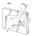
- coins such as the coin illustrated at 2 enter the validator 4 via a chute (not shown) and then fall in the direction of arrow A on to an energy-absorbing element 6. Then they roll down a ramp 8 and enter an exit path 10.
- the sensor 14 comprises two coils, schematically illustrated at L 1 and L2.
- the coil L1 is mounted on the flight deck itself, and the coil L2 is mounted on the lid (not shown) of the validator.
- the coils L1 and L2 are of similar configuration and size, and are mounted directly opposite each other. They are positioned at the appropriate distance above the surface of the ramp 8 preferably such that they are capable of being fully occluded by any coin which the validator is designed to validate.
- the coils L1 and L2 are located behind a membrane separating the front surfaces of the coils from the surfaces of the flight deck and lid, respectively, but for the purposes of clarity these membranes are not shown in the figure.
- the flight deck is oriented such that coins pass the coil L2 in close proximity thereto, but are spaced from the opposed coil L 1 by distances which depend on coin thickness.
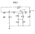
- the sensor 14 is connected in an oscillator circuit 200 comprising an inverter U1 having a feedback loop comprising a resistor R1 and the coils L1 and L2.
- the coils are connected in series, with a node A at the interconnection.
- the end of the coil L1 opposite the node A is connected, at node B, to a capacitor C1, the other end of which is connected to earth, and the end of coil L2 opposite the node A is connected, at node C, to a capacitor C2, the other end of which is connected to earth.
- This is a standard configuration for an oscillator, and the frequency of this first oscillator is determined by the resonant circuit formed by the components L1, L2, C1 and C2.
- the frequency may for example be less than 200 kHz, for example 40 khz.
- the oscillator circuit also includes a second oscillator which comprises a transistor Q1 (the base of which is supplied with a fixed, d.c. bias level from a source which has been omitted for purposes of clarity), resistor R2, capacitors C3 and C4 and the coils L1 and L2.
- a second oscillator which comprises a transistor Q1 (the base of which is supplied with a fixed, d.c. bias level from a source which has been omitted for purposes of clarity), resistor R2, capacitors C3 and C4 and the coils L1 and L2.
- This is arranged to operate at a fairly high frequency, determined by the resonant circuit formed by the components L 1 and L2 and the series combination of C3 and C4.
- the capacitors C1 and C2 effectively act as short circuits. Accordingly, the coils L1 and L2 are each effectively coupled in parallel across the series combination of capacitors C3 and C4.
- the low frequency output of the first oscillator is taken from node C, which is coupled to the input of the inverter U1. Because this is also connected via C2 to earth, and C2 is effectively a short circuit for the high frequency oscillations, node C is effectively a virtual earth for these high frequencies (i.e. no significant components of this frequency appear at this node), and therefore the low frequency signal is derived without receiving any significant influence from the high frequencies.
- the voltage at node B which is coupled to the inverter output, varies in a manner which is substantially equal and opposite to the variation at node C, which is at the input of the inverter, at the low frequency.
- L1 equals L2 and C1 equals C2
- these opposite and equal variations result in a signal null, for this low frequency, at the node A.
- the amplitudes of the oscillations will shift to an extent dependent upon the material content of the coin.
- the higher frequency output will be influenced predominantly by the material at the outer surface of the coin, and the lower frequency by both the outer and the inner material.
- the inner, or bulk, material will have a significant influence.
- the variations in the amplitudes at the two frequency outputs at nodes A and C are monitored, and the peak levels of the variation are used as measurements.
- the measurements are based on the relationship between the peak levels and the levels in the absence of a coin (for example the difference or the ratio between the peak level and the idle level).
- the two measurements are compared with acceptance criteria for respective denominations.
- Other measurements can also be made, using the same sensors and/or different sensors.
- the frequency variations as well as, or instead of, the amplitude variations of one or both of the two oscillators within the oscillator circuit of Figure 2 may be monitored. These, or other sensors may be used for obtaining measurements predominantly dependent on coin thickness and diameter.
- the oscillator circuit of Figure 2 monitors the effect of the coin at two separate frequencies, it is particularly suited for distinguishing between homogeneous coins and clad coins, and provides a particularly sensitive and compact arrangement in that the same coils are used concurrently for both frequencies.
- FIGs 3 and 4 illustrate a modification of the embodiment described above, and like reference numerals represent corresponding integers.
- this alternative embodiment instead of having a single coil on each side of the coin path, there is a pair of coils on each side.
- the coil L3 is mounted within the coil L1. Both are mounted on the same ferrite 300, part of which extends in an annulus between the two coils so as to isolate the coils, using the techniques of EP-A-489 041.
- the configuration of the coils on the lid-side of the validator is similar, and comprises an outer coil L2 and an inner coil L4.
- the oscillator which incorporates the inverter U1 has the coils connected in its feedback loop, as in Figure 2, but in this case the coils L1 and L3 are connected in series, as are the coils L2 and L4, with the series-connected L1 and L3 coils connected in parallel to the series-connected L2 and L4 coils.
- the oscillator comprising transistor Q 1 and capacitors C3 and C4. is in this case coupled to the node A' between coils L1 and L3, so that the resonant circuit is formed by the inductances L 1 and L3 which are connected in parallel (because the nodes B and C are effectively virtual earths, as in Figure 2) with each other and with the series-connected capacitors C3 and C4.
- a further oscillator of similar configuration is formed by transistor Q2, capacitors C5 and C6 and resistor R3, connected to the node A" between inductors L2 and L4.
- the circuit of Figure 4 is therefore capable of testing coins using three separate frequencies and providing three isolated outputs.
- the low frequency oscillator in contrast to the arrangement of Figure 2, has the coils on opposite sides of the coin path connected in parallel.
- the third oscillator involving transistor Q2 and capacitors C5 and C6 and resistor R3 can be omitted, the oscillator incorporating transistor Q1 being connected to both nodes A' and A".
- the acceptability data could instead represent a predetermined value such as a median, the measurements then being tested to determine whether they lie within predetermined ranges of that value.
- the acceptability data could be used to modify each measurement and the test would then involve comparing the modified result with a fixed value or window.
- the acceptability data could be a look-up table which is addressed by the measurements, and the output of which indicates whether the measurements are suitable for a particular denomination (see, e.g. EP-A-0 480 736, and US-A-4 951 799).
- the measurements may be combined and the result compared with stored acceptability data (cf. GB-A-2 238 152 and GB-A-2 254 949).
- acceptability data cf. GB-A-2 238 152 and GB-A-2 254 949.
- some of these techniques could be combined, e.g. by using the acceptability data as coefficients (derived, e.g. using a neural network technique) for combining the measurements, and possibly for performing a test on the result.
- the acceptability data to be used to define the conditions under which a test is performed (e.g. as in US-A-4 625 852).
- references herein to coins "to be validated" by the validator are intended to relate to coins of a denomination whose population exhibits average property measurements which fall within the ranges deemed by the validator to represent a particular type of coin.
- coin validators any coin (whether valid or counterfeit), token, slug, washer, or other metallic object or item, and especially any metallic object or item which could be utilised by an individual in an attempt to operate a coin-operated device or system.
- a "valid coin” is considered to be an authentic coin, token, or the like, and especially an authentic coin of a monetary system or systems in which or with which a coin-operated device or system is intended to operate and of a denomination which such coin-operated device or system is intended selectively to receive and to treat as an item of value.
- the oscillator of the invention could also be used in other areas.
Claims (16)
- Oszillatorschaltung mit mehreren Resonanzkreisen mit mindestens einer gemeinsamen Induktionsspule, wobei die Resonanzfrequenz jedes Resonanzkreises mindestens durch die Induktivität der gemeinsamen Induktionsspule und jeweilige frequenzbestimmende Komponenten der Resonanzkreise bestimmt und die Schaltung so ausgelegt ist, dass die Induktionsspule gleichzeitig mit mehreren Frequenzen beaufschlagt ist, die den jeweiligen Resonanzfrequenzen der Resonanzkreise entsprechen.
- Oszillatorschaltung nach Anspruch 1, wobei die Resonanzkreise mindestens zwei gemeinsame Induktionsspulen aufweisen.
- Oszillatorschaltung nach Anspruch 2, wobei die beiden gemeinsamen Induktionsspulen in einem Resonanzkreis in Serie und in einem anderen Resonanzkreis parallel geschaltet sind.
- Oszillatorschaltung nach einem der vorhergehenden Ansprüche mit mehreren Ausgängen zum Abgreifen von Ausgangssignalen auf jeweiligen Frequenzen, wobei mindestens ein Ausgang ein Nullsignal für die an einem anderen Ausgang abgegriffene Ausgangsfrequenz liefert.
- Oszillatorschaltung nach Anspruch 4, wobei jeder Ausgang ein Nullsignal für an anderen Ausgängen abgegriffene Ausgangsfrequenzen liefert.
- Oszillatorschaltung nach Anspruch 4 oder 5, wobei ein Ausgang für eine Frequenz eine virtuelle Erde für eine andere Frequenz darstellt.
- Oszillatorschaltung nach Anspruch 4, 5 oder 6, wobei ein Ausgang für eine Frequenz gleiche und entgegengesetzte Signale einer anderen Frequenz empfängt.
- Oszillatorschaltung nach einem der vorhergehenden Ansprüche mit einem Paar von in einer Rückkopplungsschleife in Serie geschalteten Induktionsspulen zur Bildung eines Oszillators, der einen ersten der Resonanzkreise enthält, wobei die Schwingungen an einem Ende der Serienschaltung im wesentlichen gleich und entgegengesetzt zu denjenigen am anderen Ende der Serienschaltung sind, wobei die Schwingungen an der Verbindung zwischen den Induktionsspulen im wesentlichen fehlen, und wobei die Schaltung einen weiteren Oszillator aufweist, der einen zweiten der beiden Resonanzkreise enthält, um an der besagten Verbindung Schwingungen einer anderen Frequenz zu generieren.
- Oszillatorschaltung nach Anspruch 8, mit einer Einrichtung, die zwischen den entgegengesetzten Enden der in Serie geschalteten Induktionsspulen auf der anderen Frequenz einen Kurzschluss erzeugt.
- Oszillatorschaltung nach einem der Ansprüche 1 bis 7, wobei die Resonanzkreise ein Paar von gemeinsamen Induktionsspulen aufweisen, die zu einem zur Schwingung auf einer durch den Wert der in Serie liegenden Induktionsspulen bestimmten ersten Frequenz ausgelegten Resonanzkreis in Serie geschaltet sind, wobei die Oszillatorschaltung ferner eine Einrichtung aufweist, die über die in Serie liegenden Induktionsspulen einen effektiven Kurzschluss bildet, so dass diese in dem anderen Resonanzkreis zwischen dem effektiven Kurzschlusskreis und der Serienschaltung parallel liegen, und wobei der zweite Resonanzkreis auf einer wesentlich anderen zweiten Frequenz schwingt, die ebenfalls von den Induktivitäten abhängt.
- Oszillatorschaltung nach Anspruch 10, wobei der effektive Kurzschluss auf der zweiten Frequenz, nicht aber auf der ersten Frequenz wirksam ist.
- Münzprüfer mit einer Oszillatorschaltung nach einem der vorhergehenden Ansprüche, wobei die Schaltung Ausgangssignale auf mindestens zwei verschiedenen Frequenzen aufweist, die durch das Passieren einer von dem Münzprüfer geprüften Münze beeinflusst werden.
- Münzprüfer nach Anspruch 12, mit einer Einrichtung zum Überwachen der beiden Ausgangssignale zum Erzielen von Messwerten der Münze in Abhängigkeit von den durch Annäherung der Münze bewirkte Änderungen der Ausgangssignale.
- Münzprüfer nach Anspruch 12 oder 13, wobei die Oszillatorschaltung ein Paar von auf beiden Seiten der Münzenbahn angeordneten Spulen umfasst.
- Münzprüfer nach einem der Ansprüche 12 bis 14 zum Prüfen von ummantelten Münzen, wobei eine der Frequenzen zur Erzielung von im wesentlichen vom Material der Ummantelung der Münze abhängenden Messwerten und die andere zur Erzielung einer im wesentlichen durch das Innenmaterial der Münze beeinflussten Meßwerts ausgelegt ist.
- Münzprüfer nach einem der Ansprüche 12 bis 15 mit einer Einrichtung zum Speichem von Akzeptanzkriterien für einen vorbestimmten Satz von Münzen, wobei mindestens eine der Münzen eine ummantelte Münze ist.
Applications Claiming Priority (3)
| Application Number | Priority Date | Filing Date | Title |
|---|---|---|---|
| GB9817827A GB2340681B (en) | 1998-08-14 | 1998-08-14 | Oscillators |
| GB9817827 | 1998-08-14 | ||
| PCT/GB1999/002365 WO2000010246A1 (en) | 1998-08-14 | 1999-07-21 | Oscillators |
Publications (2)
| Publication Number | Publication Date |
|---|---|
| EP1104593A1 EP1104593A1 (de) | 2001-06-06 |
| EP1104593B1 true EP1104593B1 (de) | 2006-04-05 |
Family
ID=10837330
Family Applications (1)
| Application Number | Title | Priority Date | Filing Date |
|---|---|---|---|
| EP99934918A Expired - Lifetime EP1104593B1 (de) | 1998-08-14 | 1999-07-21 | Oszillatoren |
Country Status (8)
| Country | Link |
|---|---|
| US (1) | US6556090B1 (de) |
| EP (1) | EP1104593B1 (de) |
| JP (1) | JP4856311B2 (de) |
| AU (1) | AU5054199A (de) |
| DE (1) | DE69930750T2 (de) |
| ES (1) | ES2258847T3 (de) |
| GB (1) | GB2340681B (de) |
| WO (1) | WO2000010246A1 (de) |
Families Citing this family (2)
| Publication number | Priority date | Publication date | Assignee | Title |
|---|---|---|---|---|
| AU2004275415A1 (en) * | 2003-09-22 | 2005-04-07 | Cubic Corporation | Mass transit bus fare box |
| CA2548421A1 (en) * | 2004-01-14 | 2005-07-28 | Cubic Corporation | Validating removable fare collection system |
Family Cites Families (32)
| Publication number | Priority date | Publication date | Assignee | Title |
|---|---|---|---|---|
| US3271664A (en) | 1961-12-04 | 1966-09-06 | Magnaflux Corp | Combined leakage field and eddy current detection system |
| US3229198A (en) | 1962-09-28 | 1966-01-11 | Hugo L Libby | Eddy current nondestructive testing device for measuring multiple parameter variables of a metal sample |
| US3373856A (en) | 1966-01-18 | 1968-03-19 | Canadian Patents Dev | Method and apparatus for coin selection |
| GB1397083A (en) | 1971-05-24 | 1975-06-11 | Mars Inc | Coin selector utilizing inductive sensors |
| GB1452740A (en) | 1972-10-12 | 1976-10-13 | Mars Inc | Digital memory coin selector method and apparatus |
| DE2334570B1 (de) * | 1973-07-07 | 1975-03-06 | Philips Patentverwaltung | Abstimmbare Hochfrequenz-Eingangsschaltungsanordnung fuer einen Fernsehempfaenger |
| DE2549328A1 (de) * | 1975-11-04 | 1977-05-12 | Klaus Ebinger | Schaltungsanordnung zum erzeugen von frequenzen und deren mischprodukten |
| US4128158A (en) | 1976-07-22 | 1978-12-05 | Coin Cop Co. | Precision coin analyzer for numismatic application |
| GB2045498B (en) | 1979-03-30 | 1983-03-30 | Mars Inc | Coin testing apparatus |
| GR69124B (de) | 1980-02-06 | 1982-05-03 | Mars Inc | |
| DE3136348A1 (de) * | 1981-09-14 | 1983-03-24 | Philips Patentverwaltung Gmbh, 2000 Hamburg | Mikrowellen-oszillator in gegentaktschaltung |
| US4859969A (en) * | 1983-06-13 | 1989-08-22 | The United States Of America As Represented By The Secretary Of The Army | Single transistor dual mode crystal oscillator(U) |
| US4678994A (en) | 1984-06-27 | 1987-07-07 | Digital Products Corporation | Methods and apparatus employing apparent resonant properties of thin conducting materials |
| JPS6327995A (ja) | 1986-07-21 | 1988-02-05 | 株式会社田村電機製作所 | 硬貨選別装置 |
| US4898564A (en) | 1988-08-16 | 1990-02-06 | Brink's Incorporated | Apparatus for coin sorting and counting |
| GB2234619B (en) | 1989-07-28 | 1993-04-14 | Mars Inc | Coin validators |
| GB2235559A (en) | 1989-08-21 | 1991-03-06 | Mars Inc | Coin testing apparatus |
| US5231361A (en) * | 1990-02-05 | 1993-07-27 | Trw Inc. | Voltage controlled push-push oscillator with parallel resonant tank circuits |
| US5038105A (en) * | 1990-02-09 | 1991-08-06 | Spectroscopy Imaging Systems Corporation | Series/parallel double-tuned NMR coils |
| US5057778A (en) * | 1990-03-29 | 1991-10-15 | Spectroscopy Imaging Systems Corporation | Double tuned nmr coils |
| US5167313A (en) | 1990-10-10 | 1992-12-01 | Mars Incorporated | Method and apparatus for improved coin, bill and other currency acceptance and slug or counterfeit rejection |
| US5166621A (en) * | 1990-10-26 | 1992-11-24 | Spectroscopy Imaging Systems Corporation | Multi-resonant nmr coils |
| US5263197A (en) * | 1991-09-20 | 1993-11-16 | Matsushita Communication Industrial Corporation Of America | Dual port oscillator for two-stage direct conversion receiver |
| US6075817A (en) * | 1991-12-23 | 2000-06-13 | Digital Compression Technology | Compressive communication and storage system |
| GB2266804B (en) | 1992-05-06 | 1996-03-27 | Mars Inc | Coin validator |
| JPH07176952A (ja) * | 1993-12-20 | 1995-07-14 | Sony Corp | 発振器 |
| GB2309345B (en) * | 1995-06-22 | 1998-04-29 | Univ Bristol | Radio receiver |
| AU6182798A (en) * | 1997-02-25 | 1998-09-09 | Advanced Imaging Research, Inc. | Radio-frequency coil array for resonance analysis |
| US5751140A (en) | 1997-03-25 | 1998-05-12 | Space Systems/Loreal, Inc. | Voltage converter with battery discharge protection |
| KR100574414B1 (ko) * | 1997-07-09 | 2006-04-27 | 어드밴스드 에너지 인더스트리즈 인코포레이티드 | 주파수 선택형 가변출력 인덕터 히터 시스템 및 방법 |
| US6081120A (en) * | 1998-05-20 | 2000-06-27 | Shen; Gary G | Universal-multi-layered, multi-tuned RF probe for MRI and MRS |
| US6249190B1 (en) * | 1999-08-25 | 2001-06-19 | Conexant Systems, Inc. | Differential oscillator |
-
1998
- 1998-08-14 GB GB9817827A patent/GB2340681B/en not_active Revoked
-
1999
- 1999-07-21 ES ES99934918T patent/ES2258847T3/es not_active Expired - Lifetime
- 1999-07-21 DE DE69930750T patent/DE69930750T2/de not_active Expired - Lifetime
- 1999-07-21 JP JP2000565601A patent/JP4856311B2/ja not_active Expired - Fee Related
- 1999-07-21 AU AU50541/99A patent/AU5054199A/en not_active Abandoned
- 1999-07-21 EP EP99934918A patent/EP1104593B1/de not_active Expired - Lifetime
- 1999-07-21 WO PCT/GB1999/002365 patent/WO2000010246A1/en active IP Right Grant
- 1999-07-21 US US09/762,857 patent/US6556090B1/en not_active Expired - Fee Related
Also Published As
| Publication number | Publication date |
|---|---|
| US6556090B1 (en) | 2003-04-29 |
| GB2340681B (en) | 2003-07-30 |
| WO2000010246A1 (en) | 2000-02-24 |
| DE69930750T2 (de) | 2006-11-16 |
| JP2002523911A (ja) | 2002-07-30 |
| ES2258847T3 (es) | 2006-09-01 |
| EP1104593A1 (de) | 2001-06-06 |
| GB2340681A (en) | 2000-02-23 |
| JP4856311B2 (ja) | 2012-01-18 |
| GB9817827D0 (en) | 1998-10-14 |
| DE69930750D1 (de) | 2006-05-18 |
| AU5054199A (en) | 2000-03-06 |
Similar Documents
| Publication | Publication Date | Title |
|---|---|---|
| EP0336018B1 (de) | Vorrichtung und Verfahren zum Sortieren von Münzen | |
| US4754862A (en) | Metallic article discriminator | |
| EP0496754B2 (de) | Verfahren und vorrichtung zur echtheitsprüfung von geld | |
| US4936435A (en) | Coin validating apparatus and method | |
| US5379876A (en) | Coin discrimination apparatus | |
| US4091908A (en) | Coin checking device for a vending machine | |
| EP1012796B1 (de) | Verfahren und vorrichtung zum überprüfen von münzen | |
| EP1151419B1 (de) | Geldannahmevorrichtung | |
| EP1388822A1 (de) | Geldannahmevorrichtung | |
| GB2254949A (en) | Validating coins or banknotes | |
| EP1104593B1 (de) | Oszillatoren | |
| US5615760A (en) | Method and apparatus for validating money | |
| CA2348372A1 (en) | Improved sensor for coin acceptor | |
| EP0880757B1 (de) | Münzdurchmessermessung | |
| EP1581914A2 (de) | Geldartikelakzeptor mit erweiterter sicherheit | |
| CA1327389C (en) | Moving coin validation | |
| JP3844921B2 (ja) | コイン検査方法および装置 | |
| JPS5838446Y2 (ja) | 貨幣選別装置 | |
| JPH06101054B2 (ja) | 硬貨選別装置 | |
| JPH08138109A (ja) | 硬貨識別装置 | |
| JPH06101053B2 (ja) | 硬貨選別装置 | |
| JP2002329227A (ja) | 硬貨選別装置 | |
| JPH06231334A (ja) | 硬貨選別処理装置における硬貨通路開放検知装置 |
Legal Events
| Date | Code | Title | Description |
|---|---|---|---|
| PUAI | Public reference made under article 153(3) epc to a published international application that has entered the european phase |
Free format text: ORIGINAL CODE: 0009012 |
|
| 17P | Request for examination filed |
Effective date: 20010305 |
|
| AK | Designated contracting states |
Kind code of ref document: A1 Designated state(s): AT BE CH CY DE DK ES FI FR GB GR IE IT LI LU MC NL PT SE |
|
| RBV | Designated contracting states (corrected) |
Designated state(s): DE ES FR GB IT |
|
| GRAP | Despatch of communication of intention to grant a patent |
Free format text: ORIGINAL CODE: EPIDOSNIGR1 |
|
| GRAS | Grant fee paid |
Free format text: ORIGINAL CODE: EPIDOSNIGR3 |
|
| GRAA | (expected) grant |
Free format text: ORIGINAL CODE: 0009210 |
|
| AK | Designated contracting states |
Kind code of ref document: B1 Designated state(s): DE ES FR GB IT |
|
| REG | Reference to a national code |
Ref country code: GB Ref legal event code: FG4D |
|
| REF | Corresponds to: |
Ref document number: 69930750 Country of ref document: DE Date of ref document: 20060518 Kind code of ref document: P |
|
| REG | Reference to a national code |
Ref country code: GB Ref legal event code: 732E |
|
| RAP2 | Party data changed (patent owner data changed or rights of a patent transferred) |
Owner name: MEI, INC. |
|
| REG | Reference to a national code |
Ref country code: ES Ref legal event code: FG2A Ref document number: 2258847 Country of ref document: ES Kind code of ref document: T3 |
|
| REG | Reference to a national code |
Ref country code: GB Ref legal event code: 732E |
|
| PLBE | No opposition filed within time limit |
Free format text: ORIGINAL CODE: 0009261 |
|
| STAA | Information on the status of an ep patent application or granted ep patent |
Free format text: STATUS: NO OPPOSITION FILED WITHIN TIME LIMIT |
|
| EN | Fr: translation not filed | ||
| 26N | No opposition filed |
Effective date: 20070108 |
|
| PG25 | Lapsed in a contracting state [announced via postgrant information from national office to epo] |
Ref country code: FR Free format text: LAPSE BECAUSE OF FAILURE TO SUBMIT A TRANSLATION OF THE DESCRIPTION OR TO PAY THE FEE WITHIN THE PRESCRIBED TIME-LIMIT Effective date: 20070309 |
|
| PG25 | Lapsed in a contracting state [announced via postgrant information from national office to epo] |
Ref country code: FR Free format text: LAPSE BECAUSE OF FAILURE TO SUBMIT A TRANSLATION OF THE DESCRIPTION OR TO PAY THE FEE WITHIN THE PRESCRIBED TIME-LIMIT Effective date: 20060405 |
|
| PGFP | Annual fee paid to national office [announced via postgrant information from national office to epo] |
Ref country code: ES Payment date: 20140611 Year of fee payment: 16 |
|
| PGFP | Annual fee paid to national office [announced via postgrant information from national office to epo] |
Ref country code: DE Payment date: 20140716 Year of fee payment: 16 |
|
| PGFP | Annual fee paid to national office [announced via postgrant information from national office to epo] |
Ref country code: GB Payment date: 20140716 Year of fee payment: 16 |
|
| PGFP | Annual fee paid to national office [announced via postgrant information from national office to epo] |
Ref country code: IT Payment date: 20140716 Year of fee payment: 16 |
|
| REG | Reference to a national code |
Ref country code: DE Ref legal event code: R119 Ref document number: 69930750 Country of ref document: DE |
|
| GBPC | Gb: european patent ceased through non-payment of renewal fee |
Effective date: 20150721 |
|
| PG25 | Lapsed in a contracting state [announced via postgrant information from national office to epo] |
Ref country code: GB Free format text: LAPSE BECAUSE OF NON-PAYMENT OF DUE FEES Effective date: 20150721 Ref country code: DE Free format text: LAPSE BECAUSE OF NON-PAYMENT OF DUE FEES Effective date: 20160202 Ref country code: IT Free format text: LAPSE BECAUSE OF NON-PAYMENT OF DUE FEES Effective date: 20150721 |
|
| REG | Reference to a national code |
Ref country code: ES Ref legal event code: FD2A Effective date: 20160826 |
|
| PG25 | Lapsed in a contracting state [announced via postgrant information from national office to epo] |
Ref country code: ES Free format text: LAPSE BECAUSE OF NON-PAYMENT OF DUE FEES Effective date: 20150722 |